John Schliemann
Institute for Theoretical Physics, University of Regensburg, D-93040 Regensburg, Germany
(Dated: July 2016)
Device concepts in semiconductor spintronics make long spin lifetimes desirable, and the requirements put on spin control by schemes of quantum information processing are even more demanding. Unfortunately, due to spin-orbit coupling electron spins in semiconductors are generically subject to rather fast decoherence. In two-dimensional quantum wells made of zinc-blende semiconductors, however, the spin-orbit interaction can be engineered in such a way that persistent spin structures with extraordinarily long spin lifetimes arise even in the presence of disorder and imperfections. We review experimental and theoretical developments on this subject both forn-doped andp-doped structures, and we discuss possible device applications.
PACS numbers: 71.70.Ej,85.75.-d,85.75.Hh
CONTENTS
I. Introduction 1
II. n-Doped Quantum Wells 2
A. Spin-Orbit Coupling and Growth Direction 2 B. Persistent Spin Helix: Basic theory 4
C. Spin Diffusion Equations 7
D. [001] Quantum Wells: Experiments and Simulations 8
1. Optical Techniques 8
2. Transport Measurements 10
3. Stability of the Spin Helix: Limiting Factors 11 E. Many-Body Signatures of the Persistent Spin Helix 11 F. Other Growth Directions and Geometries 12
1. [110] Quantum Wells 12
2. [111] Quantum Wells 13
3. Curved Systems 13
4. Lateral Confinement, Magnetic Fields, and Finite
Well Width 13
G. Spin Field-Effect Transistors and Related Concepts 15 III. p-Doped Structures, Topological Insulators, and other
Systems 15
IV. Conclusions and Outlook 16
Acknowledgments 16
References 17
I. INTRODUCTION
The field of semiconductor spintronics emerged around the turn of the millennium and comprises a broad vari- ety of efforts towards utilizing the spin degree of free- dom of electrons, instead, or combined with, their charge for information processing, or, even more ambitious, for quantum information processing (Fabianet al., 2007; Wu et al., 2010; Zutic et al., 2004). Most activities in this area rely on the relativistic effect of spin-orbit coupling
described by the Dirac equation and its nonrelativistic expansion in powers of the inverse speed of lightc. The well-known spin-orbit coupling term arises here in second order,
Hso= ~ 4m0c2~σ·
∇V × ~p m0
, (1)
where the Pauli matrices~σdescribe the electron’s spin, m0and~pare its bare mass and momentum, respectively, and V is the potential acting on the particle. More- over, the free Dirac equation, V = 0, has two disper- sion branches with positive and negative energy,ε(~p) =
±p
m20c4+c2p2, separated by a gap of 2m0c2≈1MeV, and the nonrelativistic expansion of the Dirac equation can be viewed as a method of systematically including the effects of the negative-energy solutions on the states of positive energy starting from their nonrelativistic limit.
Importantly, the large energy gap 2m0c2 appears in the denominator of the right hand side of Eq. (1) and thus suppresses spin-orbit coupling for weakly bound elec- trons.
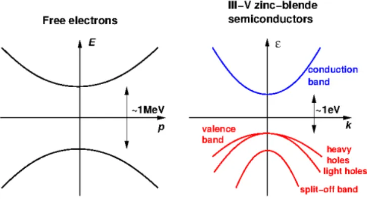
Turning to semiconductors, the band structure of zinc- blende III-V systems exhibits many formal similarities to the situation of free relativistic electrons (as sketched in Fig. 1), while the relevant energy scales are grossly dif- ferent (Yu and Cardona, 2010). For not too large dop- ing, only the band structure around the Γ point matters consisting of a parabolics-type conduction band and a p-type valence band with dispersion branches for heavy and light holes, and the split-off band. However, the fun- damental gap between conduction and valence band is of order 1eV or smaller. This heuristic argument makes plausible that spin-orbit coupling is a significant effect in III-V semiconductors and actually lies at the very heart of spintronics research.
arXiv:1604.02026v2 [cond-mat.mes-hall] 8 Sep 2016
FIG. 1 (Color online) Left: Dispersion relation of free elec- trons showing a gap of about 1 MeV between solutions of positive and negative energy. Right: Schematic band struc- ture of III-V zinc-blende semiconductors with a band gap of typically 1 eV. Thep-type valence band consists of the heavy and light hole branches, and the split-off band.
FIG. 2 (Color online) Schematic of a spin field-effect transis- tor: An electron is emitted from a spin-polarized source and enters a semiconductor region with spin-orbit coupling be- ing externally controllable via a perpendicular gate volatge.
In the aboove example the spin-orbit interaction reverses the electron’s spin during its path, and since the drain electrode is polarized opposite to the source, the conductance of the device is high.
A paradigmatic example of a semiconductor spintron- ics device is the spin field-effect transistor (Datta and Das, 1990) schematically depicted in Fig. 2. In this device proposal, an electron enters a semiconductor re- gion where its spin is rotated via externally manipula- ble spin-orbit interaction in a controlled way such that the carrier is then transmitted into or, depending on the spin state, reflected from a spin-polarized detector elec- trode. A shortcoming of this concept is that impurities and other imperfections act as scatterers which change the momentum of the electron (i.e. an orbital degree of freedom) and therefore, again via spin-orbit coupling, easily also randomize the spin, a process known as the Dyakonov-Perel mechanism of spin dephasing (Dyakonov and Perel, 1972). A way to circumvent this effect is to engineer the total spin-orbit field acting on the electron spin in such a way that additional symmetries and related conserved quantities arise which lead to persistent spin structures. This concept has developed many theoretical ramifications and manifested itself in various transport
and spectroscopic experiments. These theoretical possi- bilities and experimental achievements are reviewed in the present paper.
This article is organized as follows: Section II deals with persistent spin structures in n-doped III-V zinc- blende semiconductor quantum wells and is the main body of this review. In section II.A we introduce the con- tributions to spin-orbit coupling for quantum wells grown along the high-symmetry directions of the crystal. Sec- tion II.B provides a self-contained discussion of the the- oretical foundation of conserved spin quantities in [001]
quantum wells, but treats also the other high-symmetry growth directions. The semiclassical description of spin densities via diffusion equations and their relation to the persistent spin helix are covered in section II.C. In section II.D we report on the plethora of experiments investigat- ing these predictions along with pertaining further theo- retical work. Theoretical results regarding signatures of the persistent spin helix arising from many-body physics are summarized in section II.E. Section II.F is devoted to n-doped systems of other geometries including quantum wells of different growth directions and curved structures.
In section II.G we summarize developments regarding spin-field-effect transistors and persistent spin textures.
Section III contains a discussion of similar persistent spin structures predicted to occur in materials other thann- doped zinc-blende semiconductors. We close with an out- look in section IV
II. n-DOPED QUANTUM WELLS
A. Spin-Orbit Coupling and Growth Direction
We now summarize important features of the effective description of spin-orbit interaction in zinc-blende III-V semiconductors such as GaAs, InAs etc. focusing on two- dimensional quantum wells (Fabian et al., 2007; Korn, 2010; Winkler, 2003; Yu and Cardona, 2010). As already mentioned, due to the lower carrier densities in such sys- tems compared to, e.g., metals, we can concentrate on the vicinity of the Γ-point, i.e. on wave vectors being small compared to the inverse lattice spacing.
Moreover, we will concentrate here on quantum wells grown into the high-symmetry directions [001], [110], and [111] which have been in the focus of theoretical and ex- perimental studies so far. However, very recent work by Kammermeieret al. (2016) extended the concepts to be discussed below to more general growth directions.
An important contribution to the effective band struc- ture of three-dimensional bulk systems is the Dresselhaus term given by (Dresselhaus, 1955)
HbulkD =γ
σxkx k2y−k2z
+σyky k2z−k2x +σzkz k2x−ky2
(2)
with the electron’s (Bloch) wave vector ~k and a mate- rial parameterγ. This contribution is symmetry-allowed, γ6= 0, due tobulk-inversion asymmetry, i.e. the fact that the zinc-blende lattice lacks an inversion center.
In sufficiently narrow quantum wells a simplification occurs as one can, at low enough temperatures, approx- imate the wave vector components along the growth di- rection by their average within the lowest subband. For a symmetric well grown along the crystallographic [001]
direction we havehkzi= 0, and introducing polar coor- dinates~k = k(cosϕ,sinϕ) for the in-plane components it follows (Dyakonov and Kachorovskii, 1986; Iordanskii et al., 1994)
H001D =βk(σysinϕ−σxcosϕ)
−β3k(σxcos(3ϕ) +σysin(3ϕ)) (3) withβ=β1−β3 and
β1=γhkz2i , β3=γk2
4 . (4)
Here as before thex- andy-direction coincide with [100]
and [010], respectively. The higher angular harmonics in the second line of Eq. (3) are cubic ink. Neglecting these terms leads to
H¯D001=β(kyσy−kxσx) (5) which contains a contribution strictly linear in wave vec- tor (∝ β1) and and a cubic term (∝ β3). The latter is usually a small correction: To give a practical exam- ple, for a rectangular well of width L = 10nm we have hk2zi = (π/L)2 ≈ 0.1nm−2. Assuming now a compar- atively large density of n = k2f/(2π) = 5 ·1011cm−2 with a Fermi wave vector of kf = 0.17nm−1 (neglect- ing spin splitting) one finds k2f/4 = 0.007nm−2, i.e.
β3(kf)/β1= 0.07. However, there are reports where the quadratic contributionβ3to the Dresselhaus coefficientβ was found to be essential in order to accurately describe experimental data (Dettwiler et al., 2014; Walser et al., 2012). For simplicity we will refer to the Hamiltonian (5) as thelinear Dresselhaus termalthough it contains cubic corrections.
Quantum wells with other growth directions can be similarly described by appropriately rotating wave vec- tor and spin in Eq. (2). We restrict the discussion here on the other high-symmetry directions of the cubic lattice (Dyakonov and Kachorovskii, 1986; Eppenga and Schu- urmans, 1988). For the [110] direction one finds
H110D =β
2kyσz+3β3
2 kσzsin(3ϕ) (6) where the x- and y-direction are along [00¯1] and [¯110], respectively. The coefficient β in the first term is again given by Eqs. (4) as β = β1 −β3 and summarizes as
above the k-linear contribution and the correction pro- vided by the first-harmonic part of the cubic contri- butions, whereas the second term contains the third- harmonic part. Remarkably, both terms couple only to the spin projection in thez- (or [110]-)direction.
The Dresselhaus term for the [111] direction reads H111D = 2β
√3(kyσx−kxσy) +4β3
√6kσzsin(3ϕ) (7) with the x- and y-direction pointing along [11¯2] and [¯110]. Here the same comments apply as to Eqs. (3) and (6): The first term describes the k-linear part with cubic correction while the second term contains the higher angular-harmonic part of the cubic contributions.
Neglecting the third angular-harmonic contributions in Eqs. (6) and (7) leads again to linear Dresselhaus terms incorporating cubic corrections in their parameterβ.
The second important ingredient to the effective spin- orbit coupling in quantum wells is known as the Rashba term and is due tostructure-inversion asymmetry, i.e. it occurs for confining potentials failing to be invariant un- der spatial inversion along the growth direction (Bychkov and Rashba, 1984; Rashba, 1960). This contribution is described by the expression
HR=α(kxσy−kyσx), (8) where the Rashba coefficientαis essentially proportional to the potential gradient across the quantum well and can therefore be varied experimentally. This contribu- tion to spin-orbit interaction is the essential ingredience to the proposal for a spin field -effect transistor due to Datta and Das (1990) already mentioned in section I.
The linear Rashba term (8) is independent of the growth direction and invariant under rotations in thexy-plane of the quantum well. Remarkably, the above Hamiltonian has the same functional form as thek-linear Dresselhaus term in Eq. (7) for the [111] growth direction.
Although Rashba coupling was first investigated in semiconductors (Bychkov and Rashba, 1984; Rashba, 1960), it is nowadays discussed and studied in a much wider variety of structures lacking inversion symmetry;
for a recent overview see Manchonet al.(2015). A further source of spin-orbit coupling in two-dimensional struc- tures are assymetric interfaces (Fabianet al., 2007); such contributions will not be considered in the following.
We note that the Rashba term (8) can somewhat naively be obtained from the general expression (1) by inserting a linear potential along the z-axis. This ap- proach, however leads to values forαbeing several orders smaller than those inferred from experiments, and a real- istic description has to take into account the influence of other bands in addition to the conduction band (Darn- hofer and R¨ossler, 1993; Fabianet al., 2007; de Andrada e
FIG. 3 (Color online) Fermi contours for an electron system with band mass m = 0.067m0 (corresponding to GaAs), a typical Fermi energy ofεf = 10meV, and a Dresselhaus pa- rameter ofβ= 10meVnm. With growing Rashba parameter the energy dispersion becomes increasingly anisotropic. For the case α=β (bottom right) the spin directions being in- dependent of wave vector are indicated. Figure adapted from Schliemann and Loss (2003).
Silvaet al., 1997; Winkler, 2003; Wuet al., 2010). This procedure is effectively similar to the Foldy-Wouthuysen transformation used in relativistic quantum mechanics to reduce the full Dirac equation for four-component spinors to an effective description of the “conduction band” com- prised by solutions of positive energy (Bjorken and Drell, 1965). Here the perturbative treatment of the negative- energy states (“valence band”) leads to the spin-orbit coupling term (1), apart from other relativistic correc- tions.
B. Persistent Spin Helix: Basic theory
Let us first consider quantum wells grown in the [001]- direction. As a result of a large body of experimental as well as theoretical work (Fabian et al., 2007; Wu et al., 2010), both the parameters β and αlie for typical ma- terials and growth geometries in the ballpark of about 1.0. . .100meV˚A. In particular, the Rashba parameter can be tuned to be equal in magnitude to the Dressel- haus coefficient,α=±β. As we shall see shortly below, this situation gives rise to a prime example of a persistent spin texture in a semiconductor nanostructure.
Let us consider a Hamiltonian consisting of the usual quadratic kinetic energy characterized by a band mass
m, and the Rashba (8) and the linear Dresselhaus term (5),
H=~2k2
2m +HR+ ¯HD001. (9) leading to the two dispersion branches
ε±
~k
= ~2k2 2m ±kp
α2+β2+ 2αβsin(2ϕ) (10) which are illustrated in Fig. 3 for different typical param- eters. As seen from the figure and the above equation, the dispersion is clearly anisotropic for α6= 0 6=β. Re- markably, this anisotropy in the dispersion relation does not lead to an anisotropy of the linear electrical bulk conductivity (Chalaev and Loss, 2008, 2009; Trushin and Schliemann, 2007a), despite an earlier statement in the literature (Schliemann and Loss, 2003).
The case α = ±β shown in the lower right panel of Fig. 3 is particular (Schliemann et al., 2003): Here the Hamiltonian (9) can be formulated as
H= ~2 2m
k2+ 2
~k·Q~ Σ
(11) with
Σ =∓σx+σy
√
2 , Q~ =
√ 2mα
~2 (1,±1) (12) such that the spin operator Σ is a conserved quantity,
[H,Σ] = 0. (13)
The energy dispersions ε±(~k) = ~2
2m
k2±2
~k·Q~
(14) form circles whose centers are displaced from the Γ point by∓Q. Differently from Eq. (10) the double sign here~ refers to the spin eigenvalues determined by Σχ±=±χ±
where the eigenspinors read forα= +β χ±= 1
√ 2
1
∓e−iπ/4
, (15)
and for α = −β the lower spin component acquires an additional factor of (−i). In particular, the spin state is independent of the wave vector, i.e. spin and orbital degrees of freedom are disentangled, and the Kramers degeneracy enforced by time reversal symmetry is mani- fested as
ε+(~k−Q) =~ ε−(~k+Q)~ . (16) The conservation of the spin component Σ expressed in Eq. (13) obviously remains intact if a spin-independent single-particle potential or spin-independent interaction among the electrons are added to the Hamiltonian. In
such a case the single-particle wave vector~kwill in gen- eral not be conserved any more and is to be replaced by a proper momentum operator,~k 7→ −i∇. For example, adding an arbitrary scalar potential V(~r) to the Hamil- tonian (11) and inserting the ansatz
ψ±(~r) =e−i ~Q~rΣχ±φ(~r) =e∓i ~Q~rχ±φ(~r) (17) into Hψ± = εψ± leads to the spin-independent Schr¨odinger equation
−~2
2m∇2+V(~r)
φ(~r) =
ε+2mα2
~2
φ(~r), (18) where the energy is shifted by ~2Q2/(2m) = 2mα2/~2. An analogous many-particle Schr¨odinger equation is ob- tained when adding to (11) an arbitrary spin-independent interaction among particles; here the spin component Σ of each electron is separately conserved.
Moreover, comparing the spin state of a general wave function composed of the states (17) at given energy,
ψ(~r) =ν+ψ+(~r) +ν−ψ−(~r)
=
ν+e−i ~Q~rΣχ++ν−e−i ~Q~rΣχ−
φ(~r) (19) at two arbitrary locations, say~r = 0 and~r=~a, we see that the spin state ofψ(~a) emerges fromψ(0) by applying the operator exp(−i ~Q~aΣ). This is a controlled rotation being independent of any further detail of the system en- coded in the single-particle potential or the interaction.
As the rotation operator is also independent of energy, this observation also holds for arbitrary linear combina- tions of states of different energy. Thus, under these very general circumstances, the electron spin undergoes a con- trolled rotation as a function of position, a phenomenon dubbed later on thepersistent spin helix(Berneviget al., 2006).
The angle of the above controlled rotation is 2Q~a~ and naturally depends on the distance~a, while the rotation axis in spin space is defined by the conserved operator Σ and given by (∓1,1,0), depending on α = ±β. As a consequence, the spin component in this direction is constant as a function of both position and time leading to an infinite spin lifetimeas measured by expectation value of Σ. The latter feature is of course just a general property of any conserved operator within an equilibrium state.
Prior to the work by Schliemann et al. (2003) also other authors reported peculiarities of the system (9) at α = β although not relating their observations to the existence of a new conserved quantity. Kiselev and Kim (2000b) have studied an effective spin model of the type (9) where the momentum ~p = m~r˙ is a classical quantity (also neglecting the difference between canon- ical and kinetic momenta due to spin-orbit coupling) whose time dependence is generated by a Markov chain
modeling independent elastic scattering events. Here for general Rashba and Dresselhaus parameters, the spin is rapidly randomized via the Dyakonov-Perel spin re- laxation mechanism (Dyakonov and Perel, 1972). For α= ±β the time ordering T in the time evolution op- eratorU(t) =T exp(−iRt
0dt0H(p(t0)/~)) becomes trivial such that it takes, up to a global phase factor, the form of the above global spin rotation operator (Schliemann et al., 2003),
U(t) = exp
−i ~Q~a(t)Σ
(20) with~a(t) =~r(t)−r(0). In particular Kiselev and Kim (2000b) observed a diverging spin lifetime for expecta- tion values of Σ; a similar conclusion was reached by Cartoixa et al. (2003), slightly subsequent to the work by Schliemannet al.(2003). The suppressed relaxation of appropriate spin components was also found earlier by Averkiev and Golub (1999).
In another theoretical investigation Pikus and Pikus (1995) concluded that contributions of Rashba and Dres- selhaus spin-orbit coupling to the electrical conductivity cancel each other atα=β (albeit both terms were pre- dicted there to contribute additively to spin relaxation, in contrast to the results demonstrated above). Tarasenko and Averkiev (2002) studied the combined influence of Rashba and Dresselhaus contributions to the beating pat- terns of Shubnikov-de Haas oscillations and predicted an effective cancellation of the terms atα=β. Finally, the very fact that Rashba and Dresselhaus spin-orbit cou- pling can nontrivially interfere rather than simply add up was already observed theoretically by Knapet al.(1996) within investigations of weak localization phenomena.
Writing the Hamiltonian (11) in the form H= 1
2m
~
p+~QΣ~ 2
−~2Q~2
2m (21)
suggests to interpret the operator exp(−i ~Q~rΣ) occur- ring in Eqs. (17),(19) as a gauge transformation and
~
p as a gauge-dependent canonical momentum (Chen and Chang, 2008; Tokatly and Sherman, 2010). More- over, since the hermitian 2 × 2-matrix Σ generates SU(2)-transformations, the question arises whether the Hamiltonian (21) admits further symmetries furnishing a full representation of the Lie algebra su(2). Following Berneviget al.(2006) this can be achieved by writing the Hamiltonian in second-quantized form,
H=X
~kη
~2 2m
k2+ 2η ~Q~k c~+
kηc~kη (22) along with
T3= Σ 2 =X
~kη
η 2c+~
kηc~kη (23)
where c+~
kη (c~kη) creates (annihilates) an electron with wave vector~k and spin stateχη,η=±. Defining now
T+~
Q =X
~k
c+
(~k−Q)+~ c(~k+Q)−~ (24) and its adjointT−~
Q = (T+~
Q)+ one easily verifies that the latter two operators fulfill together with T3 the su(2) commutation relations,
hT+~
Q, T~−
Q
i= 2T3 , h T3, T±~
Q
i=±T~±
Q (25)
and commute, just asT3, with the Hamiltonian, hH, T±~
Q
i
= 0. (26)
Moreover, sinceT±~
Q also commute with any Fourier com- ponent of the densityρ~q =P
~kηc~+
kηc(~k+~q)η, h
ρ~q, T±~
Q
i
= 0, (27)
Eq. (26) remains also valid if arbitrary spin-independent potentials or interactions are added to the Hamiltonian.
We note that the su(2) commutation relation (25) as well as the property (27) hold for any vector Q. The~ vanishing of the commutator (26), however, depends on the specific form given in Eq. (12) and the fact that the spin-independent part of the kinetic Hamiltonian (11) is quadratic in the wave vector leading to the degeneracy (16). For instance, if a term quartic in the momentum were present (still consistent with time reversal symme- try), Eq. (26) would not hold, and also a formulation (21) is the style of a gauge theory would not be possible.
Applying an in-plane magnetic field perpendicular to Q~ (i.e. in the direction defined by Σ) changes the Hamil- tonian as
H0=X
~kη
~2 2mk2+η
~2 m
Q~~k+∆ 2
c~+
kηc~kη (28) with ∆ being the Zeeman gap. This alteration breaks the SU(2) symmetry down to U(1) as the Hamiltonian of course still commutes with Σ but not with T±~
Q0 for any choice ofQ~0 since
hH0, T±~
Q0
i
=X
~k
2~2 m
~k
Q~ −Q~0 + ∆
c+
(~k−Q)+~ c(~k+Q)−~ .(29) The operators T~±
Q are defined with respect to the ex- plicit spinors (15). In terms of the usual spin density S~~q = (1/2)P
~k
P
µνc~+
kµ~σµνc(~k+~q)ν defined with respect
to the original spin coordinates underlying the Hamilto- nian (9) they can be expressed as
T±~
Q =Sz
±2Q~ ±i Q~
|Q|~ ·S~±2Q~, (30) i.e. they describe the spin components perpendicular to the quantization axis defined by Σ = 2T3. Defin- ing the hermitian combinations T1 = (T+ +T−)/2, T2 = (T+−T−)/(2i), we obtain an su(2)-valued vec- tor T~ of observables commuting with the Hamiltonian.
Thus, the expectation value hT~i within any pure state is constant in time. Regarding mixed states, a sufficient condition for a constant expectation value is to demand that the density operator is only a function of the Hamil- tonian itself, ρ=ρ(H), as typical for equilibrium situa- tions. However, such a density matrix is also invariant under arbitrary spin rotations generated byT~ such that, as usual for rotationally invariant magnetic systems,hTi~ vanishes. In other words, a finite expectation valuehTi~ is the consequence of a non-equilibrium state or the result of spontaneous symmetry breaking. The latter should of course not be expected in a two-dimensional system.
For quantum wells with growth direction [110] the Dresselhaus term (6) commutes withσz. Thus, the ana- log of the Hamiltonian (9) allows for a conserved spin quantity if Rashba spin-orbit coupling is absent. In this case the Hamiltonian can again, neglecting the cubic third-harmonic contribution to the Dresselhaus coupling, be formulated as in Eq. (11) with
Σ =σz , Q~ = mβ 2~2
(0,1). (31) With these replacements, analogous properties as ob- tained above for [001] quantum wells at α = ±β fol- low. In particular, an SU(2) symmetry as described in Eqs. (22)-(27) also occurs here which is in the present case broken down to U(1) by applying a magnetic field along the growth direction (cf. Eqs. (28), (29)).
Finally, for quantum wells grown into the [111]- direction the linear part of the Dresselhaus coupling (7) and the Rashba term (8) have the identical functional form. Here a conserved quantity can only be realized if these two contributions exactly cancel each other (Car- toixaet al., 2005a,b; Vurgaftman and Meyer, 2005).
Moreover, in a very recent work Kammermeier et al.
(2016) extended the above considerations to more general growth directions. Specifically it was demonstrated that a conserved spin operator of the above type exists, for appropriately tuned Rashba coupling,if and only if two Miller indices of the growth direction agree in modulus.
Fully analogously to the cases discussed above, this con- served spin components are extended to an su(2) algebra of operators commuting with the Hamiltonian.
C. Spin Diffusion Equations
Let us concentrate again on [001] quantum wells. As seen before, for balanced contributions to spin-orbit cou- plingα=±βan electron spin undergoes a perfectly con- trolled rotation provided the locations of injection and detection of the electron are sufficiently defined, for in- stance in terms of quantum point contacts (Schliemann et al., 2003). This, however, is a rather special situation in experiments. In order to treat more general scenarios it is useful to study the expectation value of the local spin density,
~s(~r, t) =
* X
a
~
2~σaδ(~r−~ra(t)) +
, (32) where a labels the electrons, and the average h·i is to be taken over the given (in general nonequilibrium) state
in the presence of disorder potentials and/or interactions among the charge carriers. Moreover, we also include the cubic third-harmonic correction to the Dresselhaus term (3) proportional to β3. Effective semiclassical diffusion equations for~s(~r, t) can be derived via quantum kinetic equations rooted in the Keldysh formalism (Mishchenko et al., 2004). Working in Fourier space at small frequen- cies and wave vectors, and evaluating the arising param- eters within the zero-temperature ground state, one ob- tains in the regime of weak spin-orbit coupling (Bernevig et al., 2006; Liu and Sinova, 2012; Salis et al., 2014;
Stanescu and Galitski, 2007)
−iω+Dq2+Dso
¯ s1(~q, ω)
¯ s2(~q, ω)
¯ s3(~q, ω)
= 0 (33) with
Dso= 2k2fτ
(α+β)2+β23
/~2 0 i(α+β)¯q1/m 0 (α−β)2+β23
/~2 i(α−β)¯q2/m
−i(α+β)¯q1/m −i(α−β)¯q2/m 2 α2+β2+β32 /~2
. (34)
In Eq. (33) we have used a rotated coordinate system in the plane of the quantum well, ¯s1,2 = (±sx+sy)/√
2,
¯
s3=sz, and likewise for the wave vector~q, such that the new axes are along [110] and [1¯10]. D = vf2τ /2 is the usual diffusion constant given in terms of the momentum relaxation time τ and the Fermi velocity vf = ~kf/m for an effective Fermi wave vector kf (neglecting again spin splitting here). The above result (33) is valid in the regime of weak spin-orbit interaction, (α, β, β3)kfτ /~ 1. Diffusion equations similar to Eqs. (33),(34) have, for various types of spin-orbit coupling and ingredients to the many-body physics, also been derived using different theoretical techniques (Bernevig and Hu, 2008; Burkov et al., 2004; Kalevichet al., 1994; Kleinert and Bryksin, 2007, 2009; L¨uffeet al., 2013, 2011; Raimondiet al., 2006;
Schwabet al., 2006; Wenk and Kettemann, 2010; Yang et al., 2010).
All the effects of spin-orbit interaction in the diffusion equation (33) are encoded in the matrix (34). As to be expected, this equation also reflects the symmetry prop- erties arising for balanced Rashba and Dresselhaus cou- pling as analyzed in Sec. II.B: At, say,α=βthe equation for ¯s2decouples from the remaining system and reads in real space
∂t−D∇2+ 1/T1
¯
s2(~r, t) (35) with 1/T1= 2k2fτ(β3/~)2 and the general solution
¯
s2(~r, t) = e−t/T1 (2π)2
Z
d2qe−Dq2ts¯2(~q, t= 0)ei~q~r. (36)
FIG. 4 (Color online) Schematic of the persistent spin helix occuring in a [001] quantum well for spin-orbit coupling tuned toα=βaccording to Eq. (38). The shift vectorQ~defines the pitch of the helix and points along the lateral direction. The spin density component in the longitudinal direction vanishes,
¯
s2= 0. Adapted from Fabian (2009).
The latter equation describes the diffusion of an initial spin polarization, accompanied by its decay on the time scaleT1which, as suggested by the notation, is aptly re- ferred to as a decoherence time. Without the cubic third- harmonic correction to the Dresselhaus term,β3= 0, no decay occurs, and all the dynamics is due to the diffusive motion of electrons with fixed spin governed by the par- ticle (or charge) diffusion constantD. We note that the spin density can be changed by either moving the parti- cles or altering their spin. Due to the latter mechanism, the spin density does, differently from the charge den- sity, fulfill a continuity equation with additional source terms (Erlingssonet al., 2005). The infinite spin relax- ation time occurring atα=±β andβ3∝1/T1= 0 was confirmed by several authors on the basis of Monte Carlo
simulations treating the orbital carrier dynamics classi- cally (Kiselev and Kim, 2000b; Liu et al., 2010; Ohno and Yoh, 2007, 2008); for an analytical approach see also Lyubinskiy and Kachorovskii (2006) and Wenk and Ket- temann (2011).
The two other solutions to Eq. (33) are forα=β and β3= 0 characterized by the frequencies
iω±(~q) =Dq2±8k2fτ (α/~)2+ (α¯q1/m)2
. (37) Now for~qbeing twice the “shift vector”±Q~ as occurring in Eqs. (12),(16), i.e. ¯q1=±2|Q|, ¯~ q2= 0, we haveω−= 0 (Berneviget al., 2006). This static solution describes the persistent spin helix and reads in real space
s¯1(~r)
¯ s3(~r)
=A
cos
2Q~~r+φ
−sin
2Q~~r+φ
(38) with two real constants A, φ. Naturally, the angular argument 2Q~~r of the spin rotation around the [1¯10] di- rection occurring here is the same as (for~r=~a) in the effective evolution operator (20): The spatial dependence of the spin density (38) precisely mimics the rotation of the spin of an electron moving along the direction of Q.~ Fig. 4 shows a sketch of the helical spin structure de- scribed be Eq. (38).
D. [001] Quantum Wells: Experiments and Simulations We now review experimental work investigating the high-symmetry situationα=±βin [001] quantum wells, along with numerical simulations and pertinent theoret- ical approaches.
1. Optical Techniques
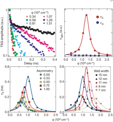
The stability of periodic spin structures in GaAs quan- tum wells close to the regimeα≈β has been experimen- tally studied by Koraleket al.(2009) using the technique of transient spin-grating spectroscopy. Here a periodic spin pattern with defined wave vector~qis created via op- tical orientation by two noncollinear laser beams, and its time evolution is then monitored by diffraction of a time- delayed probe pulse. The initial spin density structure is a superposition of two helices with the same~qk[110] but different senses of rotation, only one of which matches the one encoded in the static solution (38). Accordingly, Ko- raleket al.(2009) observe that the initial spin polariza- tion decays, to about equal weights, on two very distinct time scales as shown in Fig. 5: A short-lived part where the life time shows a maximum atq= 0 and slowly de- creases with growing wave number, and a fraction with clearly enhanced lifetime attaining a pronounced maxi- mum atq≈106m−1. The latter should be interpreted as
FIG. 5 (Color online) Upper left panel: Decay curves of spin gratings obtained by Koraleket al.(2009) for different wave numbersqof the initially modulated spin density. The data shows decay on two distinct time scales. Upper right panel:
Lifetimes of the spin helices with enhanced (τE) and reduced (τR) stability. The former one corresponds to the spin density configuration (38) with a maximum lifetime atq= 2Q. Lower panels: Lifetime of the spin helix configuration as a function of wave number for different doping asymmetry (varying the Rashba coupling, left) and well width (varying the Dressel- haus term, right). Adapted from Koraleket al.(2009)
.
a persistent spin helix (38) withq= 2Q= 4mα/~2 cor- responding to a Rashba parameter ofα≈3meV˚A. The fact that these measurements indeed explore the regime α≈βwas further established by varying the Rashba and Dresselhaus parameter (see lower panels of Fig. 5): The first was achieved by studying samples with altered rel- ative concentration of the remote dopants on both sides of the quantum well at fixed total density of dopants, while in the latter case samples of different well width were compared.
In a related experimental study Yang et al.(2012) in- vestigated, also using transient spin-grating spectroscopy, the drift dynamics of spin helices in the presence of an electric field directed in the plane of asymmetric quan- tum well with a vanishing Rashba but finite Dresselhaus parameter. These spin helices have of course per se a finite lifetime.
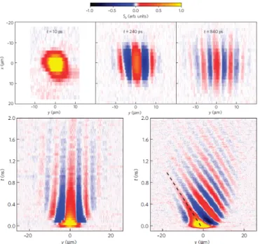
The formation of a persistent spin helix was directly observed by Walseret al.(2012) using spatially and tem- porally resolved Kerr microscopy. The authors moni- tored the time evolution of a local spin polarization along the growth (orz-)direction produced by a focused pump
FIG. 6 (Color online) Kerr rotation data obtained by Walser et al.(2012). The detection method is sensitive to the out- of-plane component sz of the spin density. Upper panels:
Time evolution of the persistent spin helix from an initial local spin polarization along the growth direction (left) generated by a pump laser. Here the x- and y direction point along [1¯10] and [110], respectively, and the detection method is only sensitive to the out-of-plane component sz(~r, t) of the spin density shown. Lower panels: Time evolution of the spin density in zero magnetic field (left) and in an in-plane field of B=-1T along [1¯10] rotating the in-plane spin components into the growth direction. Adapted from Walseret al.(2012).
laser. The upper panels of Fig. 6 show the spreading of this initial wave packet by diffusion: The z-component of the spin density evolves, due to the combined Rashba and Dresselhaus spin-orbit coupling nearα= +β, into an oscillatory pattern along the [110]-direction, consistent with numerical simulations by Liu et al. (2009, 2006).
As to be expected, the spin density pattern is constant in the orthogonal [1¯10]-direction. Similar as in the measure- ments by Koraleket al.(2009), the detection technique is only sensitive to thez-component of the spin density. Ap- plying an external magnetic field in [1¯10]-direction cou- pling to the conserved spin component Σ rotates the in- plane component of the helix into the growth direction and enables its detection (lower panels of Fig. 6). We note that, as seen in Eqs. (22), (29), introducing such an external field breaks the SU(2) symmetry at α=β.
Thus, the work by Walser et al.(2012) is an experimen- tal demonstration that the stability of the persistent spin helix does not depend on the full SU(2) symmetry but the existence of the single conserved spin component Σ suffices.
The investigations by Walser et al. (2012) were per- formed in a [001]-grown GaAs quantum well with the
Rashba parameter fixed by asymmetric doping. Ishihara et al.(2014a) have conducted a similar imaging study on a sample where the Rashba parameter was varied by a gate voltage close toα=−β. In a companion study the same authors used Kerr imaging to map out the spin dy- namics in quantum wires lithographically defined in the quantum well along the [110]- and [1¯10]-direction (Ishi- hara et al., 2014b). In accordance with Eqs. (11), (12) (again forα = −β), the spin-orbit coupling was in the former case (where ~k ⊥ Q~ ) found to be strongly sup- pressed while in the latter direction a spin helix was formed. Similar results on spin dephasing time scales for quantum wires in GaAs wells close toα=−β were reported by Denegaet al. (2010) .
Salis et al. (2014) combined the experimental tech- niques of Walseret al.(2012) with theoretical simulations to study the formation of a spin helix, again following a local optical spin excitation, under imperfect conditions.
Specifically, the authors considered a finite imbalance
|α|−β 6= 0, a substantial third-harmonic cubic correction to the Dresselhaus term, and lateral confinement within the quantum well. The experimental results obtained again for GaAs samples are found to agree well with the theoretical modeling. Only shortly later the same collab- oration (Altmannet al., 2014) investigated, in a similar experimental setup, the spin helix lifetime near α = β in quantum wires etched along the direction [110]kQ~ in quantum wells originating from the same wafer as used before (Walser et al., 2012). By fitting their data to a spin diffusion model (Salis et al. (2014), cf. Sec. II.C) the authors conclude that the observed enhanced stabil- ity of the helix is mainly due to the geometrical confine- ment while the intrinsic lifetime is rather unaffected and still determined essentially by the cubic third-harmonic contribution to the Dresselhaus term.
Sch¨onhuberet al.(2014) have investigated via inelastic light scattering intrasubband spin excitations in a GaAs quantum well close toα = β produced again from the same wafer as used by Walseret al.(2012). For momen- tum transfer along the direction ofQ~ k[110] a substan- tial spin splitting is found, while this quantity is clearly suppressed in the opposite direction, in accordance with Eqs. (11), (12) and the findings by Ishiharaet al.(2014b) (working at α = −β). The spin orbit parameters ex- tracted from the measurements are consistent with the results by Walseret al.(2012).
Most recently, two studies extended the work by Yang et al.(2012) mentioned above on spin helix drift in quan- tum wells now close toα=±β. Kunihashiet al. (2016) investigated drift spin transport via Kerr imaging in a four terminal geometry of ohmic contacts covered by a semi-transparent Au gate electrode. The latter varied the Rashba coupling while voltages applied to the con- tacts created drift transport of optically injected spin- polarized electrons. Wells of two widths (L= 15nm and
FIG. 7 (Color online) Magnetoconductance as measured by Kohdaet al.(2012) for different gate voltages in two quantum wells differing in width. In the narrower well (left) a transi- tion from weak antilocalization to weak localization and back occurs. From Kohdaet al.(2012).
L= 25nm) were studied with the wider one being close to α=−β, and a clearly enhanced spatial coherence of the drifting spin pattern was observed here. The authors also demonstrated the modulation of the electron trans- port path upon applying time-dependent drift voltages.
Altmann et al. (2016) used samples of the same struc- ture as Walser et al. (2012) to perform a Kerr imaging study concentrating on the situation where the diffusive current of the optically injected spin density is compen- sated by the drift current. Here a spin precession is found with a frequency proportional to the drift velocity. Using an appropriate model for the carrier distribution func- tion (being anisotropic as a function of wave vector) the authors explain this effect with properties of the cubic Dresselhaus term.
2. Transport Measurements
Kohdaet al.(2012) have investigated the quantum cor- rections to the magnetoconductance in InGaAs quantum wells with spin-orbit coupling close toα=β. Spin-orbit interaction combined with scattering on imperfections generically randomizes the spin leading to weak antilocal- ization signaled by a negative magnetoconductance (Ket- temann, 2007; Knap et al., 1996; Sch¨apers et al., 2006;
Wirthmann et al., 2006). For Rashba and linear Dres- selhaus spin-orbit interaction atα=±β, however, spins are left unaltered along closed trajectories which should give rise to weak localization, i.e. a positive magneto- conductance. Kohdaet al. (2012) applied the magnetic field perpendicular to the quantum well and used a gate voltage across it to vary the Rashba parameter α. As shown in Fig. 7, in a comparatively narrow well of width L = 4nm the authors found a transition from weak an-
tilocalization to weak localization and back when driving the gate voltage through an appropriate critical value. In a sample with a larger well width ofL= 7nm and there- fore smaller Dresselhaus parameter β no such behavior was observed, i.e. in the latter systemβ and the range ofαseem to be too different to match each other. The experimental results are corroborated by numerical sim- ulations which conclude that the weak localization signal persists even if the cubic third-harmonic term in Eq. (3) is included, but its location in parameter space is shifted away fromα=β.
The fact that the L= 4nm sample actually has spin- orbit coupling parameters close toα=β was also estab- lished by Kohdaet al.(2012) in an independent experi- ment using the spin-galvanic effect. This phenomenon amounts in an electric current to response to an in- plane spin polarization, and its directional dependence is highly sensitive to the ratio α/β (Ganichev et al., 2004; Ganichev and Golub, 2014; Trushin and Schlie- mann, 2007a), which was indeed found to be close to unity.
Dettwiler et al.(2014) extended the investigations by Kohda et al.(2012) using GaAs quantum wells varying in width fromL= 8nm toL= 13nm. Employing a com- bination of top and back gates the Rashba parameterα and the carrier densityncould be tuned independently.
The point α = β was again determined by monitoring the transition from weak antilocalization to weak local- ization and back. To obtain a consistent data analysis it was necessary to take into account the cubic correction (being proportional ton) to the Dresselhaus parameter β. As a result, Dettwileret al.(2014) demonstrated con- trol over spin-orbit coupling parameters and carrier den- sity while preserving the conditionα=β. At quite high densities such asn= 9·1011cm−2 no transition between weak antilocalization and localization was found which should be ascribed to the third-harmonic correction to the Dresselhaus term that also increases with density.
Magnetoconductance studies in quantum wires in the directions [100], [110], [1¯10] of an [001] InGaAs quan- tum well were performed by Sasakiet al.(2014) building upon theoretical work by Scheidet al.(2008). To reduce fluctuation effects the authors used arrays of wires which were arranged in the same sample thus enabling simulta- neous measurements. The Rashba coupling was varied by a top gate, and the magnetic field lay in the plane of the well leading in combination with the spin-orbit coupling to a strong anisotropy of the magnetoconductance which additionally depends on the direction of the wire. In a one-dimensional quantum wire spin randomization due to momentum scattering (Dyakonov-Perel mechanism) is quenched since effective wave vector-dependent field provided by the spin-orbit interaction is unidirectional.
This phenomenon will be discussed in more detail in sec- tion II.F.4. An in-plane magnetic field noncollinear with the spin-orbit field changes this situation and leads spin
randomization favoring weak antilocalization. Thus, in accordance with numerical simulation done by the au- thors, the weak localization signal in the conductance is maximal if the applied field is collinear with the field pro- vided by the spin-orbit coupling. With the direction of the wave vector defined by the quantum wire, the latter observation provides a means to determine the ratioα/β.
In particular, for α/β = 1 no anisotropy of the mag- netoconductance is observed for transport in the [1¯10]- direction since here we have~k⊥Q~ (cf. Eqs. (11), (12)).
If the applied magnetic field is substantially noncollinear with the spin-orbit field it randomizes the spin and sup- presses weak localization. Assuming that this process is most efficient if both fields are of the same magni- tude (as indicated by the numerics), Sasakiet al.(2014) also give reasonable separate estimates forαandβ. For a further proposal to determine the relative strength of the Rashba and Dresselhaus coupling utilizing the high- symmetry point|α/β|= 1 see Li and Chang (2010).
Most recently, Yoshizumi et al. (2016) have demon- strated gate-controlled switching betweenα=±β in an InAlAs quantum well. The occurrence of each persistent spin helix (differing by sense of rotation) was again de- tected by similar magnetoconductance measurements as above.
3. Stability of the Spin Helix: Limiting Factors
Several theoretical studies have identified the cubic Dresselhaus term as the main decay mechanism of the persistent spin helix (Cheng and Wu, 2006; Chenget al., 2007; Kettemann, 2007; Kurosawaet al., 2015; Liu and Sinova, 2012; L¨uffeet al., 2011; Lusakowskiet al., 2003;
Shen and Wu, 2009; Wenk and Kettemann, 2011), in ac- cordance with experiments already mentioned (Koralek et al., 2009; Saliset al., 2014).
Specifically, the spin-grating experiments by Koralek et al.(2009) found the spin lifetimeτhof the symmetry- protected spin helix to be of order a few hundred pi- coseconds, depending significantly on temperature. The ratio of τh and the time scale of ordinary (spin) diffu- sion can be expressed as η := 4DQ2τh. This quantity is approximately constant, η ≈ 100, below 50K while it decreases for higher temperature with a power law showing an exponent slightly larger than 2. The sub- sequent theoretical analysis by Liu and Sinova (2012) concluded that this temperature dependence cannot be quantitatively described by a low-order treatment of the spin-orbit interaction which is essentially restricted to the Dyakonov-Perel regime and leads to the diffusion equa- tions (33), (34) (given here at zero temperature). This finding is in qualitative agreement with the experimen- tal study by Studer et al. (2009) on InGaAs quantum wells using time-resolved Faraday rotation. Instead the Elliot-Yafet relaxation mechanism should also be taken
into account which yields expressions somewhat more in- volved than Eqs. (33), (34).
Theoretical investigations by L¨uffeet al.(2013, 2011) led to the prediction that the spin helix life time can be enhanced by Coulomb repulsion (treated there within Hartree-Fock approximation). A study of Rashba and Dresselhaus coupling and its interplay with Coulomb in- teraction described by the GW approximation was pre- sented by Nechaevet al.(2010).
A further possible source of decoherence of the spin helix are spatial inhomogeneities of the effective Rashba coupling (Bindel et al., 2016; Glazov et al., 2010a; Liu et al., 2006).
E. Many-Body Signatures of the Persistent Spin Helix We now summarize the role of persistent spin textures in connection with the many-body physics of interact- ing systems. If not mentioned otherwise, we consider electrons in [001] quantum wells subjected to Coulomb repulsion and spin-orbit coupling of the Rashba and the linear Dresselhaus type.
Badalyan et al. (2009, 2010) evaluated the dielectric function of the two-dimensional electron gas within Ran- dom Phase Approximation (Lindhard formula). For α = ±β one obtains the dielectric response of system without spin-orbit coupling, while for general parameters a beating of the static Friedel oscillations is observed. In a subsequent work the charge density relaxation propa- gator, i.e. the slope of the imaginary part of the polariza- tion function, and its analyticity properties was studied (Badalyanet al., 2013).
The optical conductivity was calculated by Maytorena et al. (2006) and compared with the frequency depen- dence of the spin Hall conductivity (which vanishes in the static limit (Schliemann, 2006)). The authors pre- dict a rich phenomenology arising from the interplay of the two spin-orbit coupling terms. In a subsequent work the analysis was extended to the optical (i.e. spatially homogeneous) spin susceptibility (Lopez-Bastidaset al., 2007). The optical conductivity for quantum wells with Rashba and Dresselhaus coupling was reconsidered by Li et al.(2013). As a signature of the persistent spin helix, all interband transitions vanish at α = ±β. If the cu- bic Dresselhaus contribution is taken into account, these transitions are rendered finite but still suppressed.
Cappset al.(2015) studied the finite-temperature equi- librium state of an interacting electron gas atα = ±β within Hartree-Fock approximation and concluded the absence of any helical spin structures; a finding consis- tent with the fact that, as discussed in section II.B, finite expectation values of the operators (23), (24) occur only in nonequilibrium states or as the result of spontaneous symmetry breaking. Most recently, the authors have ex- tended their analysis to the spin Seebeck effect (Capps
et al., 2016).
The RKKY interaction between magnetic moments in the presence of spin-independent disorder was investi- gated by Chesi and Loss (2010). Here the disorder- averaged susceptibility shows a twisted exchange inter- action decaying exponentially with distance. Iglesias and Maytorena (2010) have investigated the dynami- cal spin-polarization, i.e the linear response of the spin- magnetization to a homogeneous in-plane electric field.
The authors consider Rashba and Dresselhaus spin-orbit coupling in quantum wells with growth directions [001], [110], and [111].
When the electrons are confined to a quantum wire (and their interaction is neglected) the spin-orbit cou- pling in general leads to anticrossings of the single- particle subband dispersions except for the caseα=±β where, due to the additional conserved quantity, cross- ings occur (Schliemannet al., 2003). Using a Luttinger liquid description, Menget al. (2014) studied the renor- malization of such (anti-)crossings in the presence of Coulomb repulsion. This effect especially significant near the high-symmetry pointα=±β where the anticrossing gap vanishes with an interaction-dependent power law in the spin-orbit parameters.
F. Other Growth Directions and Geometries
We now review, among other items, experimental stud- ies dedicated to persistent spin structures in quantum wells of the other high-symmetry growth directions [110]
and [111]. A very recent prediction of analogous phe- nomena in systems of more general growth direction has been already mentioned (Kammermeieret al., 2016). For a summary of experimental work on spin-orbit coupling in such systems (not specifically addressing spin helices) we refer to Ganichev and Golub (2014).
1. [110] Quantum Wells
As seen in Sec. II.B, for quantum wells grown in the [110]-direction a conserved spin component along with an SU(2) symmetry involving an appropriate wave vec- tor transfer occurs in the absence of Rashba coupling.
Relying on optical techniques several groups reported on clearly enhanced spin dephasing times compared to those observed in quantum wells of other growth direc- tions (Bel’kov et al., 2008; Couto et al., 2007; M¨uller et al., 2008; Ohno et al., 1999; Schreiber et al., 2007a,b;
V¨olkl et al., 2011, 2014). Moreover, spin dephasing is found to be strongly anisotropic depending on whether the spin polarization lies in the plane of the quantum well or along the growth direction where the longest life- times occur (D¨ohrmann et al., 2004; Griesbeck et al., 2012). These observations are of course in agreement
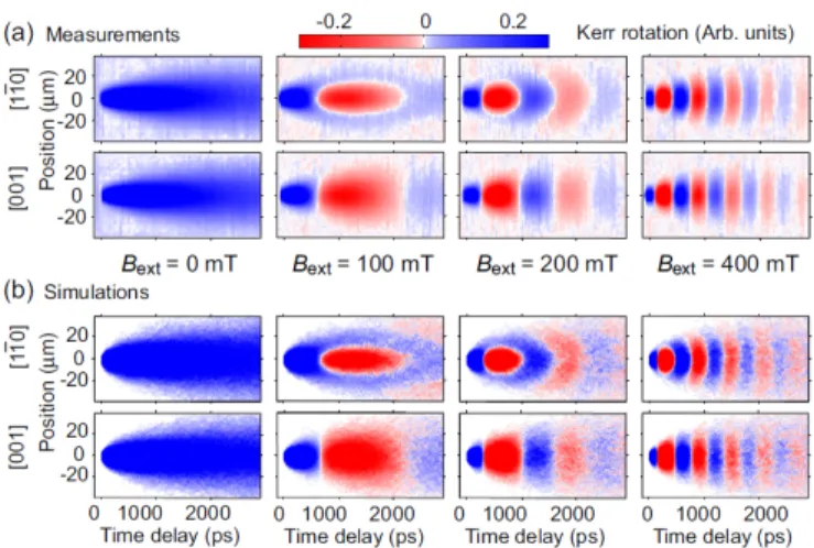
FIG. 8 (Color online) Upper panels (a): Time- and spatially resolved Kerr rotation data by Chenet al.(2014). The dy- namics of an initial spin polarization along the [110] growth direction is followed along the [1¯10] and [001] direction. To generate nontrivial dynamics a magnetic fieldBextof various strength is applied along [1¯10]. Lower panels (b): Corre- sponding Monte Carlo simulation results. From Chenet al.
(2014).
with the structure of the Dresselhaus spin-orbit coupling, and the remaining spin decay can be attributed to resid- ual Rashba coupling (Glazov et al., 2010b; Poshakin- skiy and Tarasenko, 2013; Tarasenko, 2009) and/or hole- mediated processes (V¨olklet al., 2011).
Experiments directed explicitly towards helical spin structures were performed by Chen et al. (2014) who studied [110]-grown GaAs quantum wells using time- resolved Kerr microscopy. To generate a finite net spin- orbit field averaged over the the Fermi contour, the Fermi disk was shifted from its equilibrium position by applying a DC current of up to 200µA. The direction of the current defines the direction of the effective wave vector to be in- serted in the Dresselhaus Hamiltonian (6). Additionally a magnetic field of order a few hundred mT was applied.
By comparing data obtained for different directions of the magnetic field, the authors were able to extract the energy contribution due to spin-orbit interaction. For a current along the the [1¯10]- (or y-)direction this quantity is proportional to the current strength, while for the or- thogonal [001]- (or x-)direction it is more or less constant, in accordance with the form of the Dresselhaus term (6).
Similar to the studies by Walser et al.(2012) on [001]
quantum wells, Chenet al. (2014) also mapped out the formation of a helical spin structure following a local in- jection of spin density polarized along the growth direc- tion. As this direction coincides with the direction of the spin-orbit field, an additional small magnetic field was necessary to generate nontrivial dynamics. Fig. 8 shows the time-resolved data which is well reproduced by Monte Carlo simulations.
2. [111] Quantum Wells
According to Eqs. (7) and (8), the linear Dresselhaus coupling in quantum wells grown in the [111]-direction can exactly cancel the Rashba term for α = 2β/√
3.
Thus, spin-orbit interaction is present only in higher cor- rections, the leading one being third-harmonic contribu- tion in Eq. (7). This situation in GaAs quantum wells was investigated by Balocchi et al. (2011) using time- resolved photoluminescence spectroscopy. For an appro- priate Rashba coupling tuned by a gate voltage, the au- thors observed clearly enhanced spin lifetimes exceeding 30ns for all spin directions. Spin polarizations perpendic- ular to the growth direction were generated by a trans- verse magnetic field of order a few hundred mT. In a subsequent work, Ye et al. (2012) found, for structures as used by Balocchi et al. (2011), the sign of the gate voltage to depend on whether the underlying GaAs [111]
substrate is terminated by a [111]A (Ga-rich) or [111]B (As-rich) surface.
Independent confirmation for the above findings was provided by Biermann et al. (2012) and Hernandez- Minguezet al.(2012) who performed photoluminescence measurements on GaAs [111] quantum wells of somewhat larger width; for a summary see also Hernandez-Minguez et al.(2014). Wang et al.(2013) recorded both the spin lifetimeτsand the momentum relaxation timeτin GaAs [111] quantum wells and deduced an enhanced spin dif- fusion lengthls=√
Dτs,D =v2fτ /2, at an appropriate gate voltage. Moreover, Balocchiet al.(2013) combined optical experiments and theoretical simulations to inves- tigate the influence of the cubic third-harmonic contri- bution to the Dresselhaus coupling close to the cancella- tion of the linear part with the Rashba term. The au- thors conclude that effective control over spin relaxation even at room temperature should be possible in suffi- ciently narrow [111] wells where the linear Dresselhaus term dominates.
3. Curved Systems
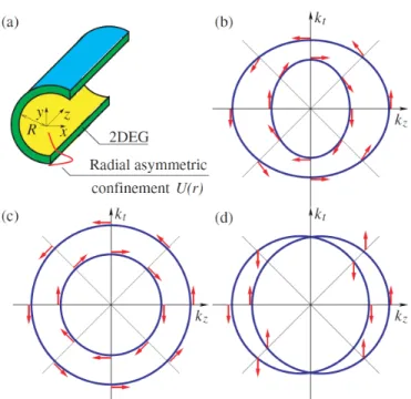
Another situation where, for appropriately tuned spin- orbit interaction, nontrivial conserved spin quantities occur is realized by evenly curved cylindrical two- dimensional electron systems. The geometry of such sam- ples is sketched in Fig. 9(a); for the practical fabrication of such structures see, e.g., Mendachet al.(2004, 2006);
and Schmidt and Eberl (2001).
Including Rashba spin-orbit coupling, the Hamiltonian can be formulated as (Trushin and Schliemann, 2007b)
H=~2k2z
2m + ~2q2ϕ 2mR2 +α
kzσϕ−qϕ
Rσz
(39) where kz is the wave vector component along the (z- )axis of the cylinder of radius R, and qϕ = −i∂/∂ϕ
generates real-space rotations around the axis. σϕ =
−σxsinϕ+σycosϕis the projection of the Pauli matri- ces on the azimuthal direction such that [σϕ, σz]/(2i) = σxcosϕ+σysinϕ=:σr. For general Rashba parameter αthe above Hamiltonian leads to anisotropic dispersions shown in Fig. 9(b), differently from the case of aflatsys- tem discribed by the Hamiltonian (8) and depicted in Fig. 9(c).
One easily finds the commutator [H, σϕ] =
~2 2mR2 + α
R
(qϕσr+σrqϕ) (40) which vanishes if the Rashba parameter fulfills
α=− ~2
2mR, (41)
a result that remains obviously valid if arbitrary spin- independent potentials or interactions are added to the Hamiltonian (39). Moreover, in full analogy to flat quan- tum wells with appropriately tuned Rashba and Dressel- haus parameter, the conservation of Σ = σϕ leads to circular dispersion relations displaced by a shift vector (cf. Fig. 9(d)). Thus, analogous to Eqs. (23), (24), we have a complete su(2) algebra of operators commuting with the Hamiltonian (Trushin and Schliemann, 2007b).
Finally, the corresponding persistent spin structure can also be described via appropriate spin diffusion equations (Kleinert and Bryksin, 2009).
Independently of the condition (41) the Hamiltonian (39) always commutes with the total angular momen- tumj =qϕ+σz/2, and electrons in superpositions the samejbut opposite spin orientation show interesting pe- riodic spin patterns along the cylindrical axis (Bringer and Sch¨apers, 2011).
As a somewhat related geometry, Nowak and Szafran (2009) studied circular quantum rings embedded in [001]
quantum wells with Rashba and Dresselhaus spin-orbit coupling. Here the latter leads, except for the high- symmetry caseα=±β, to elliptical deformations of the confined electron density.
4. Lateral Confinement, Magnetic Fields, and Finite Well Width
Duckheim et al. (2009) performed a theoretical study of the dynamical spin Hall effect (Duckheim and Loss, 2007) in a two-dimensional electron gas confined to a channel of finite width. Specifically, the spin accumula- tion at the channel boundary in response to a AC electric field along the channel direction was investigated. This effect is found to typically decay on the length scale set by the spin-orbit coupling. However, considering addition- ally a DC in-plane magnetic field at balanced spin-orbit couplingα=±βthe authors were able to identify condi- tions under which such spatially oscillating spin profiles
![FIG. 4 (Color online) Schematic of the persistent spin helix occuring in a [001] quantum well for spin-orbit coupling tuned to α = β according to Eq](https://thumb-eu.123doks.com/thumbv2/1library_info/5290754.1676916/7.918.457.843.217.746/color-online-schematic-persistent-occuring-quantum-coupling-according.webp)