This content has been downloaded from IOPscience. Please scroll down to see the full text.
Download details:
IP Address: 132.199.103.61
This content was downloaded on 18/04/2016 at 16:43
Please note that terms and conditions apply.
Magnetotransport in disordered two-dimensional topological insulators: signatures of charge puddles
View the table of contents for this issue, or go to the journal homepage for more 2015 2D Mater. 2 024005
(http://iopscience.iop.org/2053-1583/2/2/024005)
2D Mater.2(2015) 024005 doi:10.1088/2053-1583/2/2/024005
PAPER
Magnetotransport in disordered two-dimensional topological insulators: signatures of charge puddles
Sven Essert and Klaus Richter
Institut für Theoretische Physik, Universität Regensburg, D-93040 Regensburg, Germany E-mail:Sven.Essert@ur.de
Keywords:2d topological insulators, HgTe/CdTe quantum wells, magnetotransport, charge puddles, spin–orbit coupling, disorder
Abstract
In this numerical study we investigate the influence and interplay of disorder, spin–orbit coupling and magnetic
field on the edge-transport in HgTe/CdTe quantum wells in the framework of coherentelastic scattering. We show that the edge states remain unaffected by the combined effect of moderate disorder and a weak magnetic
field at realistic spin–orbit coupling strengths. Agreement with theexperimentally observed linear magnetic
field dependence for the conductance of long samples isobtained when considering the existence of charge puddles.
1. Introduction
Both from a fundamental and from an applications viewpoint, two-dimensional (2d) topological insula- tors (TI) are very promising because of their quasi-one dimensional (1d) edge states, which are (unlike many other 1d quantum systems) protected against localiza- tion due to elastic disorder scattering. This protection is guaranteed by time-reversal symmetry. Hence, one question that quite naturally arises is how fast the edge channels exhibit backscattering and eventually localize under the application of an external magneticfield.
The first published experiments on HgTe/CdTe quantum wells [1,2] showed an almost linear depen- dence of the edge conductance on the magneticfield and suggested a strong suppression of the edge trans- port already for lowfield strengths which was repro- duced by other groups [3]. These measurements were, however, performed with samples much larger than the coherence length which did not show a quantized conductance at zero field. For smaller samples in which the transport is assumed to be fully coherent, the conductance remains unaffected by the magnetic field up to highfield strengths [4]. Correspondingly, in thefirst experiments of InAs/GaSb based TI the trans- port in small systems turned out to be robust while long non-quantized samples were more fragile with respect to the magnetic field [5]. However, recent experiments in this material system show that one can also produce long samples which are robust up to at least 1 T [6].
On the theory side, there are already a few publica- tions dealing with different aspects of the edge-trans- port properties of 2d-TIs (mainly focusing on HgTe/
CdTe) under the influence of a perpendicular mag- neticfield using various methods [7–12]. We will not discuss them all in detail but we would like to mention a calculation by Maciejkoet al[7] which considers the combined effect of elastic disorder scattering and applied magneticfield. Within this model theyfind a strong and almost linear magneticfield dependence of the conductivity, very similar to thefindings for the experiments on long HgTe/CdTe samples but differ- ent from results on the short HgTe/CdTe samples in which the quantized conductance is observed. This is surprising as this theory assumes a fully coherent transport picture, something that one would rather assume to be fulfilled for the short but not for the longer samples. In addition, there are later theory cal- culations which use a comparable calculation setup [8,11] but show a much weaker influence of the mag- neticfield.
Here we present a systematic study, including elas- tic disorder scattering, spin–orbit interaction and magnetic field. Thereby, we try to resolve this dis- crepancy, and find out whether it is possible to describe both scenarios (long and short samples).
Note that we are restricting our scope to the influ- ence of a moderate perpendicular magneticfield. We will, e.g., not consider band structure changes which are expected at much largerfields leading to a phase transition of the TI to a quantum hall phase [13].
OPEN ACCESS
RECEIVED
17 February 2015
ACCEPTED FOR PUBLICATION
16 March 2015
PUBLISHED
5 May 2015
Content from this work may be used under the terms of theCreative Commons Attribution 3.0 licence.
Any further distribution of this work must maintain attribution to the author(s) and the title of the work, journal citation and DOI.
© 2015 IOP Publishing Ltd
In thefirst part of this manuscript, we have a close look at the influence of elastic backscattering and dis- order on the edge transport in HgTe/CdTe ribbons.
Wefind that the effect of the magnetic field is very weak but it becomes stronger at disorder strengths high enough to make the bulk of the material con- ductive as it is undergoing a phase transition to a trivial insulator. We show that this disorder-induced phase transition may be used to experimentally control the edge transport by creating samples with inhomoge- neous disorder. In the last part, we reexamine the effect of local metallic puddles which are not due to disorder but due to locally gated regions which may be naturally present owing to trapped charge impurities.
The transport through such puddles does indeed show the strong linear dependence that was found by [2,3], supporting the fact that this magnetoconductance sig- nature may be a hint to the presence of charge puddles in these materials.
2. Theory
We use the Bernevig–Hughes–Zhang (BHZ) Hamilto- nian [14] to model the electronic structure of HgTe/
CdTe quantum wells
Δ Δ Δ Δ
=
−
− −
H h
h k
k ( ) 0
0 0
0 * ( )
, (1)
⎛
⎝
⎜⎜
⎜
⎞
⎠
⎟⎟
⎟
with spin-subblock Hamiltonians
= − + +
− + − +
+
−
h M B D V Ak
Ak M B D V
k k
k
( ) ( )
( )
, (2)
2
2
⎛
⎝
⎜⎜
⎞
⎠
⎟⎟
wherek±=kx±ikyandk2=kx2+ ky2. The material parameters A,B,D,M and Δ are taken from k p· -calculations [2]. Here, Δ=1.6 meV is accounting for the spin–orbit coupling resulting from bulk inver- sion asymmetry.Vincludes the effects of an electro- static potential, which will be applied in the second part of this publication. We do not include Rashba spin–orbit coupling, the size of which is strongly depending on the detailed layer structure of the quantum well. However, we did some test calculations that show that the effects presented in this manuscript are qualitatively unchanged under the inclusion of an additional Rashba coupling term. For similar reasons, we also do not include Zeeman terms as we found that they are of minor importance for the scenario that we discuss, i.e., transport in a moderate perpendicular magneticfield.
For the numerical transport calculations this Hamiltonian is discretized on a regular grid with lat- tice constanta=5 nm. The disorder is taken to be of Anderson type, meaning that it will be on-site disorder drawn from a box-distribution Vdis= −[ W W, ] which enters the Hamiltonian on the same footing as the electrostatic potential. It is important to note at
this point that the‘effective strength’of the disorder, e.g., the influence of the disorder on the mean free path, is not given by the amplitude W alone but includes the lattice discretization which is the inherent correlation length of the on-site disorder. The effective strength is then roughly given bya W2 . This is impor- tant when comparing disorder strengths across simu- lations which use a different lattice spacing. Also this means that one should not attempt to compare the mere amplitude of the disorder strength with other energies, like the band gap of the material as this amplitude will vary with the (arbitrarily chosen) dis- cretization. It would therefore be useful not to just plot the amplitude but instead always use the combination a W2 as an indicator of the effective disorder strength.
However, we did not do this in this publication to sim- plify the comparison with phase diagrams calculated in other publications which also use the same lattice constant as we do (a=5 nm).
The magnetic field is implemented as a Peierls phase for the hopping matrix elements. In thefirst part of this publication we consider a scattering geometry as shown infigure1(a), i.e., a simple ribbon geometry with clean leads and a central scattering region. As dis- cussed in the introduction, we are mainly interested in the scattering properties of the edge states under the influence of an external magneticfield. We therefore choose the Fermi energy of the system in the gap by setting EF=0 meV such that only edge states con- tribute to transport in the clean system.
The possible scattering paths in this geometry are listed infigure1(b) together with their dependence on the presence of spin–orbit coupling and magnetic field. However, the processes that connect the two edges (like the spin-conserving edge-to-edge reflec- tion which is always allowed by symmetry) will be strongly suppressed as long as the disorder is small enough to keep up the insulating behavior of the bulk.
In this regime (insulating bulk), the on-edge spin-flip backscattering (bottom panel in figure 1(b)) is the only non-trivial scattering pathway but it requires both spin–orbit coupling and a magneticfield. It is for this reason that the edge state transport is expected to be exceptionally ballistic.
For the above geometry, the low temperature transport coefficients and the local density of states,
x y
d( , ), are calculated with a recursive Green function algorithm [15]. From d( , )x y we extract a quantity which we call the spread of the local density of states
∫ λ=
∫
θ
(
−) (
+ −) (
θ −)
, (3)
x y y L y L y y L x y
x y x y
d( , ) 2 2 d d
d( , )d d
y y y
⎡⎣ ⎤
⎦
with θ( )y being the Heaviside step function. It is a measure of the distance of the regions with a high local density of states from the sample edge.
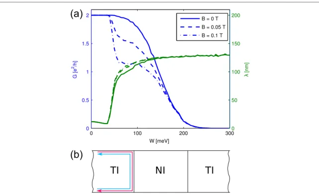
Figure 1.(a) Scheme of the ribbon geometry used for transport calculations (different spin orientations are marked in blue and red).
The Fermi energy is chosen such that there are only edge states present in the leads. The meaning ofλ, cf (3), is shown on an exemplary transverse local density of states profile (green). (b) The table lists all the possible scattering paths in the above geometry (changes of color along a path indicate spinflip due to spin–orbit (SO) coupling). In addition, it shows how some of these paths are symmetry forbidden in the absence of spin–orbit coupling or magneticfield. Scattering paths through the bulk (to the other edge, e.g. in the third panel) will be strongly suppressed due to the bulk being insulating as long as the disorder strength is small enough.
Figure 2.(a) Disorder averaged results of the transmission (blue) and the spread of the local density of states (green) as a function of disorder strengthW, for a ribbon geometry as shown infigure1(a), withLx=1000 nmandLy=500 nm. The average was taken over 1000 disorder realizations. (b) Sketch of the scenario for very strong disorder: the scattering region turns into a trivial Anderson insulator and the edge states are topologically reflected right at the interface to the scattering region.
3
2D Mater.2(2015) 024005 S Essert and K Richter
3. Results
3.1. Magnetotransport of disordered ribbons Infigure 2(a) typical results are shown for the total transmission as a function of disorder strength (blue lines) through such ribbons for different magnetic fields (shown as full, dashed, and dashed–dotted). One notes that there is no visible effect of the magneticfield for small disorder strengths (W<40 meV): although the appliedfields are on the order of a fewflux quanta penetrating the ribbon, the transmission stays at the quantized value of2e h2 . At aroundW≈40 meVthe applied magneticfield reduces the conductance. How- ever, from this disorder strength onwards, also the conductance at zerofield is below the quantized value.
This implies that there are also edge-to-edge processes contributing, as pure on-edge-backscattering is sym- metry-forbidden at zero magneticfield, cffigure1(b).
For example the bulk material in this disorder range is no longer a good insulator and there is afinite edge-to- edge coupling. This is reflected in the spread of the local density of states, λ, which is also depicted in figure2(a) (green lines). It shows that the transport is very closely localized along the edge (λ< 15 nm) for small disorder strengths and undergoes a sharp transi- tion aroundW≈ 40 meV. For strong disorder we see a complete spread of the local density of states (λ≈Ly 4 =125 nm). Note that also the influence of the magnetic field decreases in this strong disorder regime.
These phenomena can all be understood by con- sidering the phase diagram for disordered HgTe- quantum wells [16,17]. For the Fermi energy at which the previous calculations where performed (EF=0 meV), it shows that one expects the bulk material to undergo a phase transition from a topolo- gical insulator to a topologically trivial Anderson insu- lator for a disorder strength of around100 meV. This phase transition is of the localization–delocalization type, for which the localization length diverges at the phase transition. For ourfinite-sized scattering region this implies that there will be a small intermediate metallic regime between the two insulating phases, for which the localization length is large compared to the sample size1. The effect of the magneticfield seems to be largest in this intermediate metallic regime. It is actually only in this regime that the on-edge back- scattering, the fourth process infigure1(b), has non- negligible amplitude. This is understandable in a semi- classical way when thinking of the scattered electrons in terms of diffusive trajectories. Only if they enclose a sizable amount offlux the time-reversal symmetry can be effectively broken through dephasing thus allowing on-edge backscattering. This is not possible if the tra- jectories are bound close to the edge (as in the case of a
truly insulating bulk). Considering the phase transi- tion, one can also understand the behavior in the strong-disorder limit. As the phase above the transi- tion will be topologically trivial, we face a situation as depicted in figure 2(b), which we dub topological reflection. As the leads are clean and topologically non- trivial, topological edge states form along the bound- ary to the scattering region. The dominant process will thus be an edge-to-edge reflection, the third process in figure1(b), which (given that the bulk is sufficiently insulating) will again involve only 1d states. This explains why the effect of the magneticfield decreases for larger disorder and the spread of the local density of states approaches that of an even distribution.
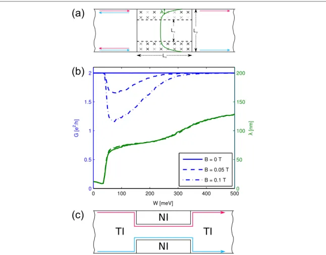
To fully exclude edge-to-edge backscattering, we choose a calculation setup as shown infigure3(a), i.e., we restrict the disordered region to the edges of the sample and leave a clean strip in the center of the scat- tering region. In this way, there will always be a truly insulating layer that prevents the coupling of the two edges. Results of these calculations are shown in figure3(b). For low disorder strengths wefind similar results as in the previously discussed setup: there is no effect of the magneticfield on the transport when the disorder strength is low enough that there is pure 1d edge transport (W<40 meV). At around W≈40 meVthe spread of the local density of states
increases and reaches an intermediate plateau at around 75 nm which corresponds to an equal dis- tribution over the whole disorder region and is a clear sign of the intermediate metallic phase. In this region, the magneticfield leads to a strong reduction of the transmission. Interestingly, this effect decreases again, for very high disorder strengths (W>200 meV). This seems paradoxical atfirst glance, as one would expect an increased backscattering at a given magneticfield for higher disorder strengths, but can also be under- stood when thinking about the previously mentioned phase diagram and by looking at the spread of the local density of states. In this limit, the value forλapproa- ches150 nmmeaning that the transport is now mainly localized at the interface of the clean and the dis- ordered region leading to a transport scenario as depicted infigure3(c): at these high disorder strengths the disordered region becomes more and more (Anderson) insulating, and eventually acts almost like a perfect insulator. For an interface with a perfect insu- lator, however, one again has 1d edge transport of the (now relocated) topological edge states. As we dis- cussed previously, those are not very susceptible to the effects of a magneticfield because of their purely 1d nature.
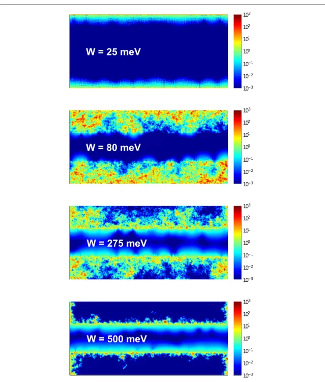
To see that we indeed obtain a scenario as depicted infigure3(c), one may look at snapshots of the local density of states for afixed disorder configuration, as shown infigure4. Here, one clearly can see the descri- bed transition from pure edge transport along the outer edge to another edge transport situation, where the strong disorder just acts as an effective Anderson
1Interestingly, the position of the phase transition seems to be unaffected by the additional magnetic field, at least up to the magneticfield values that we considered.
insulator. Also one clearly observes the intermediate metallic regime, where the transport is full delocalized over the whole disorder region (second panel in figure4).
The fact that strong disorder regions effectively act like a trivial insulator with new edge states connected to the interface of these disorder regions to clean TI has already been observed in the context of three- dimensional TI [18]. However, to our knowledge it has not been seen in a transport setup and it may show an alternative way of patterning such materials. E.g., one could think of using ion beams to locally create strong disorder patches instead of etching away the material which should lead to similar results in terms of edge state transport.
Summing up the results obtained so far, wefind that the 1d edge transport along the edges of a 2d topo- logical insulator turns out to be very robust against the combined effect of disorder and magneticfield. This is in line with experimental results on smaller samples but differs from the numericalfindings of [7] in which a strong response of the transmission was observed already at moderate disorder strengths and small mag- neticfields. In this publication they observe an almost
linear dependence of the transmission on the magnetic field. This seems surprising atfirst glance, as the calcu- lations performed in [7] were done with a similar method that is also used in the present publication.
The main difference between [7] and the study at hand is that [7] makes a small but seemingly impor- tant modification to the ribbon calculation setup that is shown infigure 1(a), by introducing an artificial mass term in the Hamiltonian for the uppermost row of cells used with the intention to additionally decou- ple the edges similar to the clean gap that we used.
They also use a very small clean gap of30 nm. We sus- pect that especially the mass term is responsible for the strong magneticfield signature that they observe even at low disorder strengths. In our calculation, we also find this strong signature, but only in the parameter range where the disorder strength is already large enough to lift the insulating behavior of the bulk and create an extended metallic region, i.e., in the range of W>40 meVinfigures2(a) and3(b).
As already noted in [7], this strong almost linear response to the magnetic field seems to agree with experimental results on larger samples. In view of our results, this suggests the existence of metallic patches
Figure 3.(a) Scheme of the ribbon geometry in which the disorder is limited to the edges of the sample and a clean gap is left between the two disorder patches on the sides. In this way the two edges are fully decoupled as there is always a clean insulating region separating them. (b) Disorder averaged results for the transmission (blue) and the spread of the local density of states (green), for a gapped geometry as shown in (a), withLx=1000 nm,Ly=500 nmandLc=200 nm. The average was taken over 1000 disorder realizations. (c) Sketch of the scenario for very strong disorder: the disorder regions turn into trivial Anderson insulators and one observes one-dimensional edge states running around their boundaries.
5
2D Mater.2(2015) 024005 S Essert and K Richter
in these long samples which would lead to such a mag- netoresistance signature. However, we do notfind it very likely that these metallic patches are due to strong inhomogeneous disorder, but they might come about due to locally trapped charges which act like a local gate on the sample and in this way create small metallic puddles. The existence of such puddles was also hypo- thesized by experimentalists and considered in other theories as they might be responsible for the back- scattering of the edge states at zerofield which would explain the non-quantized transport in these samples [19–23]. As this is symmetry forbidden in the coherent single-particle picture, these theories focus on inelastic
two-particle backscattering or include additional pro- cesses which break the phase coherence of the wave function evolution.
In the following second part, we will study in more detail the influence of such metallic puddles in the fra- mework of single-particle scattering and focus on the combined effect of disorder, spin–orbit interaction and magneticfield in such a setup.
3.2. Effect of local gating
To study the effect that a local metallic puddle would have in terms of the magnetoconductance in
Figure 4.Color plots of the local density of states (arbitrary units) of the scattering region in a logarithmic scale for the setup shown in figure3(a) for different disorder strengthsW. The results were obtained on a single disorder realization. They nicely show the transition from pure edge transport at the outer boundary to edge transport along the disorder region (as illustrated infigure3(c)) with the intermediate metallic regime in which the current is carried all over the disordered region.
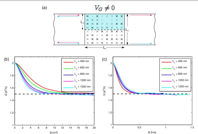
connection with a small amount of disorder, we devise a calculation geometry that is shown infigure5(a): a local gate is added to one side of the ribbon, which creates a metallic puddle of lengthLxand widthLG. The lower edge is not gated and its edge state propagates unaffectedly, as we will choose the disorder smaller than the critical disorder needed to trigger the insulator-to-metal phase transition discussed above.
Results for the transmission obtained for such a geometry are shown infigure5(b) as a function of the magneticfield for different lengths of the gated region.
The disorder strength is chosen at a small value of W=5 meVwith a potential shift due to the gate vol- tage ofVG=50 meV. The drop in transmission with increasing B, in presence of spin–orbit coupling Δ, results from scattering paths as sketched in the bottom panel offigure1(b). The results already resemble the ones obtained in [7] and also the experimental results on larger samples in the fact that they show a strong and almost linear behavior for smallfields2. If one set the gate voltage to zero, i.e., one were looking at true 1d edge states, one would not see any response to the magneticfield at this disorder strength (cffigure2(a)).
This also explains why the conductance obtained in our calculations is always larger than one as there is always the contribution of the (almost) freely propa- gating edge state of the lower edge. Looking more clo- sely at the results, we see that the obtained curves all show a very similar behavior. In particular the value for largefields is roughlyG B( ≫1)≈ 1.5e h2 for all calculated setups even though the gated sections strongly differ in their length. This means that the edge states on one edge get reflected with a50%probability suggesting that the gated region shows the behavior of a chaotic cavity randomizing the exit direction. And indeed, in a closer analysis of the scattering matrices connected to the transmission values we found that the submatrix of the scattering matrix that describes the scattering of the upper edge states in this para- meter range behaves as if it was drawn from the two- dimensionalcircular unitary ensembleCUE(2). In par- ticular, this means that the transmission values obtained for a single sample follow a box distribution on the interval[0, 1], i.e., they are completely random, which on average leads to this 50% transmission probability.
Going from zero magneticfield to afinitefield, we observe a transition from an on-edge scattering matrix which is perfectly transmitting to a CUE(2)-matrix.
The magnetic field scale on which this transition
Figure 5.(a) Scheme of the ribbon geometry with an additional local gate that creates a metallic patch on one edge of the sample. The other edge is unaffected and the two edges are decoupled by the insulating bulk, given that the disorder is not chosen too strong. (b) Disorder averaged results for the transmission for the setup shown in (a) as a function of the magneticfield and different lengthsLxof the gated region, with widthLG=250 nm,Ly=500 nmat a disorder strength ofW=5 meVand a potential shift due to the gate of VG=50 meV. The average was taken over 1000 disorder realizations. (c) The same dataset as in (b) plotted as a function of the magneticflux through the gated area, which shows that already oneflux quantum through the gated area is enough to trigger a transition to completely chaotic scattering in the puddle.
2The behavior very close toB= 0 is quadratic which agrees with other models for edge state localization [10] but it turns over to a linear dependence very quickly.
7
2D Mater.2(2015) 024005 S Essert and K Richter
happens is given by the number offlux quanta pene- trating the gated region. This is best illustrated in figure5(c), where the data fromfigure5(b) is replotted over theflux in the gated region measured in units of h e. One observes that now the data sets almost repro- duce a single curve and show that already a magnetic flux on the order of a singleflux quantum is sufficient to obtain the chaotic scattering regime.
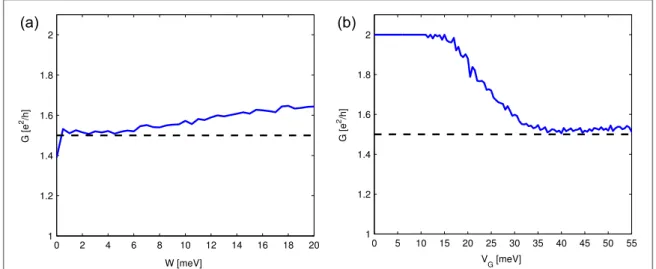
To show that this CUE-regime is obtained over a wider parameter range, we made additional calcula- tions in which we varied the disorder strength and the gate voltage, leaving the magneticflux big enough to be in the chaotic transport regime. Looking at the results which are shown infigures6(a) and (b) one sees that one obtains an extended plateau exhibiting the char- acteristic CUE-transmission ofG=1.5e h2 showing that this is indeed a quite generic case for low disorder strength and the puddle sizes considered here.
Given that the transport through a puddle has a wide parameter regime which shows this generic trans- port behavior it is tempting to try to quantitatively relate this to the measured magnetoconductance of HgTe/
CdTe quantum well samples. However, for this one has to face the major complication that the experimental samples likely contain more than one single puddle that we have considered so far. As shown in [10], the loga- rithm of the transmission would be self-averaging in such a series of scatterers and the averages of the loga- rithmic transmissions of single puddles would add up to yield the total logarithmic transmission, i.e.
∑
=
=
T t
ln ln .
n N
n tot
1
Assuming that the puddles are all of the same type and that we are restricting ourselves to the low field behavior, in which the disorder averaged transmission of one puddle is close to one, it is roughly given by a
linearflux dependence for smallfields
ϕ ϕ
〈t( )〉 =1− ϕ ,
c
cffigure5(c), with the slope1ϕc. Supposing that the sample hasNpuddles on the edge and all have the same areaA, one can infer the total edge transmission from the average transmission for a single puddle〈t( )ϕ〉:
ϕ ϕ ϕ ϕ
ϕ ϕ
ϕ
= 〈 〉
≈ −
= − +
= − +
( ) ( )
T N t
N
N
NBA B
exp ln exp ( ln ( ) ) exp
1
1 . (4)
c
c
c tot
2
2
⎛
⎝⎜⎜ ⎞
⎠⎟⎟
Thus, the slope of the conductance at lowfields would be related to the product of the number of puddles and the typical puddle area, i.e., the total area of all puddles.
The experimentally extracted values for the slope of the conductance at small magnetic fields
σ B σ B
d[ ( ) (0)] d in long samples range from
≈0.5(1 T)[24] to≈50(1 T)[1]. If the puddles were in the universal CUE-regime, their transmission slope at zerofield would be roughly given byϕc≈ 0.5h e, cf figure5(c). This would correspond to a total puddle area in the sample of1000 nm2resp.100 000 nm2, i.e., a total linear puddle size of only30 nmresp.300 nm which seems to contradict the assumption of the puddles being in the CUE-regime, as this area would be too small for that3if it would be not just one puddle.
Figure 6.Disorder averaged results for the transmission of the setup with a one-sided gate (cffigure5(a)) at afinite magneticfield,
=
B 15 mT, as a function of (a) the disorder strength at afixed gate voltageVG=50 meVand (b) as a function of the gate voltage at fixed disorder strengthW=5 meV. The lengths defining the device geometry areLG=250 nm,Ly=500 nmandLx=1000 nm. One sees that the discussed chaotic scattering regime,G≈1.5e h2 , is not just obtained for a single parameter set but can be observed over a larger parameter range.
3In our numerical calculations, we only observe the CUE-regime at linear puddle sizes larger than ≈100 nm for VG=50 meV. For smaller puddles there is a non-vanishing chance that the electrons directly traverse the puddle without being scattered chaotically leading to an overall average transmission which remains above 0.5 even in the regime of ergodic dynamics.
So from the perspective of fully elastic coherent transport one could draw the conclusion that the puddles in the experimental samples should either be shallower thanVG=35 meV, cffigure6(b),or smaller than100 nm. Then their magnetoconductance signa- ture would still be similar tofigure5(c) but it would saturate at a value above0.5 e2 h, the slope at zerofield would be decreased and would be compatible with the experimentally determined slopes.
However, this argumentation breaks down if the puddles present in the sample already lead to back- scattering even at zerofield, which is one hypothesis to explain the non-quantized zerofield resistance in long samples. This could be due to the transport being partly incoherent [19] or due to Coulomb interactions [22,23], both of which are not included in this work but would—given the processes are sufficiently strong
—also lead to an asymptotic 50–50 backscattering probability of the puddle. The additional effect of a magneticfield acting on such a puddle which already at zero field starts out closer to this 50–50 limit is expected to be strongly reduced, i.e., ϕc>0.5h e which would also allow the existence of larger puddles in such samples. We are currently preparing a quanti- tative study on the influence of dephasing on the zero field backscattering [25].
As seen on the above argumentation, it is still diffi- cult to make definite statements about the situation in current experimental samples. We therefore see a need for more experiments on small well defined systems in which one studies the influence of a single artificial puddle by adding a local gate. With this, the applic- ability of the presented coherent elastic theory could be verified which would provide a solid basis for the interpretation of results in longer samples.
4. Conclusion
Using a model which includes only elastic coherent disorder scattering, wefind qualitative agreement with magnetoconductance results on long samples of HgTe/CdTe quantum wells (acting as a 2d TI) if we assume the existence of charge puddles in the material.
Without charge puddles onefinds the edge states to be uninfluenced by the combined effect of magneticfield, spin–orbit coupling and disorder. This changes only if one increases the disorder to a strength at which the material is already on the phase transition to a topologically trivial Anderson insulator, a scenario which we do not find very likely to occur in the available materials as it would imply that one should not be able to observe the measured quantized conductance and non-local transport phenomena.
This is in line with other numerical studies which also obtained robust edge states under the combined influence of magnetic field and disorder [8,11] but disagrees with [7] in which a magnetoconductance signature similar to our results for a charge puddle is
observed in a setup without puddles, i.e., only considering magnetic field and disorder. However, this publication uses a modified calculation setup including an artificial mass term which might modify the magnetoconductance signature in a way that they are probing the regime of very strong disorder.
The interpretation that the puddles are responsible for the measured magnetoconductance signature would also be in line with the observation that the quantized conductance observed in short samples is robust under the influence of an applied field. One could argue that there is a chance that the short sam- ples which show the quantized conductance are small and clean enough not to contain any charge puddles while this would be statistically unlikely for larger samples.
The presented theory is still incomplete in the sense that it can not account for the observed back- scattering (non-quantized conductance) at zerofield that is ubiquitous in all measurements on long HgTe/
CdTe quantum well samples. However, a number of theories also ascribes this backscattering to the exis- tence of puddles due to their inherent dephasing [19]
or their enhanced electron–electron backscattering [22,23]. These effects (backscattering, loss of elec- tron phase coherence), however, are not expected to be strongly influenced by the magneticfield. It might therefore well be that this elastic coherent theory accounts for the influence of the magneticfield while the zerofield backscattering is due to other processes, the common root of both being the existence of charge puddles. Without further experiments how- ever, this remains highly speculative. We therefore strongly recommend to focus the experimental effort especially on short samples which show the quan- tized longitudinal conductance at zerofield4. In these samples one could introduce artificial puddles by adding a local gate with which one could check the predictions of this manuscript and therefore the validity of the BHZ model and the applicability of a fully coherent elastic theory. For such a test experi- ment, we recommend the discussed CUE-regime, a wide parameter regime in which the puddle is show- ing ‘maximal conductance fluctuations’, i.e., fully random transmission values t∈ [0, 1]. As this is expected for a wider range of gate voltages and mag- neticfields one should be able to detect this regime even in a single sample without the need for an addi- tional disorder average. In addition, one would also be able to check the influence of the puddle on the transmission at zerofield which could provide valu- able clues about the backscattering mechanism in long samples5.
4Published results for the magnetoconductance of such a HgTe/
CdTe sample would be desirable.
5 We are currently preparing a quantitative study about the influence of dephasing in a single charge puddle [25].
9
2D Mater.2(2015) 024005 S Essert and K Richter
So far we have not done any calculations on the other very promising material system InAs/GaSb.
However, we would expect that it behaves similarly under the application of an external gate, i.e., we also expect the existence of a CUE regime, and this has indeed already been seen in other numerical simula- tions [26].
In passing, we observed that the phase transition caused by very strong disorder might provide a new way of patterning the samples: instead of removing the unwanted material, one could consider to strongly dis- order it, e.g., by ion beam irradiation to render it topo- logically trivial and thereby modify the current path of the topological edge states.
Acknowledgments
This work is supported by Deutsche Forschungsge- meinschaft (SPP 1666 and joined DFG-JST Research Unit FOR 1483). We thank V Krueckl for many helpful discussions throughout the course of this work and I Adagideli as well as M Wimmer for useful conversations.
References
[1] König M, Wiedmann S, Brüne C, Roth A, Buhmann H, Molenkamp L W, Qi X L and Zhang S C 2007Science318 766–70
[2] König M, Buhmann H, Molenkamp L W, Hughes T, Liu C X, Qi X L and Zhang S C 2008J. Phys. Soc. Japan77031007
[3] Gusev G, Kvon Z, Shegai O, Mikhailov N and Dvoretsky S 2014Solid State Commun.2054–8
[4] Buhmann H 2013 private communication
[5] Knez I, Du R R and Sullivan G 2011Phys. Rev. Lett.107 136603
[6] Knez I, Rettner C T, Yang S H, Parkin S S P, Du L, Du R R and Sullivan G 2014Phys. Rev. Lett.112026602
[7] Maciejko J, Qi X L and Zhang S C 2010Phys. Rev.B82155310 [8] Chen J C, Wang J and Sun Q F 2012Phys. Rev.B85125401 [9] Xue Y and Prodan E 2012Phys. Rev.B86155445 [10] Delplace P, Li J and Büttiker M 2012Phys. Rev. Lett.109
246803
[11] Pikulin D I, Hyart T, Mi S, Tworzydło J, Wimmer M and Beenakker C W J 2014Phys. Rev.B89161403
[12] Essert S, Krueckl V and Richter K 2014New J. Phys.16113058 [13] Scharf B, Matos-Abiague A and Fabian J 2012Phys. Rev.B86
075418
[14] Bernevig A B, Hughes T L and Zhang S C 2006Science314 1757–61
[15] Wimmer M and Richter K 2009J. Comput. Phys.2288548–65 [16] Prodan E 2011Phys. Rev.B83195119
[17] Li J, Chu R L, Jain J and Shen S Q 2009Phys. Rev. Lett.102 136806
[18] Schubert G, Fehske H, Fritz L and Vojta M 2012Phys. Rev.B85 201105(R)
[19] Roth A, Brüne C, Buhmann H, Molenkamp L W, Maciejko J, Qi X L and Zhang S C 2009Science325294–7
[20] König Met al2013Phys. Rev.X3021003 [21] Grabecki Get al2013Phys. Rev.B88165309
[22] Väyrynen J I, Goldstein M and Glazman L I 2013Phys. Rev.
Lett.110216402
[23] Väyrynen J I, Goldstein M, Gefen Y and Glazman L I 2014 Phys. Rev.B90115309
[24] Gusev G, Olshanetsky E, Kvon Z, Mikhailov N and Dvoretsky S 2013Phys. Rev.B87081311
[25] Essert S, Krueckl V and Richter K 2015 in preparation [26] Mi S, Pikulin D I, Wimmer M and Beenakker C W J 2013Phys.
Rev.B87241405(R)