Tracking and Level-1 triggering in the forward region of the ATLAS Muon Spectrometer at sLHC
This article has been downloaded from IOPscience. Please scroll down to see the full text article.
2012 JINST 7 C01048
(http://iopscience.iop.org/1748-0221/7/01/C01048)
Download details:
IP Address: 134.107.5.116
The article was downloaded on 10/01/2013 at 12:14
Please note that terms and conditions apply.
View the table of contents for this issue, or go to the journal homepage for more
Home Search Collections Journals About Contact us My IOPscience2012 JINST 7 C01048
PUBLISHED BYIOP PUBLISHING FORSISSA RECEIVED: November 7, 2011 REVISED: December 13, 2011 ACCEPTED: December 14, 2011 PUBLISHED: January 10, 2012
T
OPICALW
ORKSHOP ONE
LECTRONICS FORP
ARTICLEP
HYSICS2011, 26–30 S
EPTEMBER2011,
V
IENNA, A
USTRIATracking and Level-1 triggering in the forward region of the ATLAS Muon Spectrometer at sLHC
B. Bittner, J. Dubbert, H. Kroha, R. Richter
1and P. Schwegler
Max-Planck-Institute for Physics,Munich, Germany
E-mail: richterr@mpp.mpg.de
A
BSTRACT: In the endcap region of the ATLAS Muon Spectrometer (η > 1) precision tracking and Level-1 triggering are performed by different types of chambers. Monitored Drift Tube cham- bers (MDT) and Cathode Strip Chambers (CSC) are used for precision tracking, while Thin Gap Chambers (TGC) form the Level-1 muon trigger, selecting muons with high transverse momentum (p
T). When by 2018 the LHC peak luminosity of 10
34cm
−2s
−1will be increased by a factor of
∼ 2 and by another factor of ∼ 2–2.5 in about a decade from now (“SLHC”), an improvement of both systems, precision tracking and Level-1 triggering, will become mandatory in order to cope with the high rate of uncorrelated background hits (“cavern background”) and to stay below the maximum trigger rate for the muon system, which is in the range of 10–20 % of the 100 kHz rate, allowed for ATLAS.
For the Level-1 trigger of the ATLAS Muon Spectrometer this means a stronger suppression of sub-threshold muons in the high-p
Ttrigger as well as a better rejection of tracks not coming from the primary interaction point. Both requirements, however, can only be fulfilled if spatial resolution and angular pointing accuracy of the trigger chambers, in particular of those in the Inner Station of the endcap, are improved by a large factor. This calls for a complete replacement of the currrently used TGC chambers by a new type of trigger chambers with better performance. In parallel, the precision tracking chambers must be replaced by chambers with higher rate capability to be able to cope with the intense cavern background.
In this article we present concepts to decisively improve the Level-1 trigger with newly devel- oped trigger chambers, being characterized by excellent spatial resolution, good time resolution and sufficiently short latency. We also present new types of precision chambers, designed to maintain
1Corresponding Author
2012 JINST 7 C01048
excellent tracking efficiency and spatial resolution in the presence of high levels of uncorrelated background hits, as generated by γ and neutron conversions.
K
EYWORDS: Large detector systems for particle and astroparticle physics; Muon spectrometers;
Trigger detectors; Particle tracking detectors (Gaseous detectors)
2012 JINST 7 C01048
Contents
1 Introduction 1
2 Precision chamber concepts for the endcap of the Muon Spectrometer 2 2.1 MDT chambers with Small Tubes for tracking at high background rates 2 2.2 Micromega chambers for tracking at high background rates 5 3 Trigger chamber concepts for the endcap of the Muon Spectrometer 6 3.1 Combined TGC plus sMDT chambers for the Inner Station of the endcap 6 3.2 Combined RPC plus sMDT chambers for the Inner Station of the endcap 7 3.3 The Level-1 trigger function of the micromega chambers 8
3.4 Comparision of the proposed chamber concepts 9
4 Summary 9
1 Introduction
While peak luminosities at the SLHC will be 4–5 times higher compared to the LHC design lumi- nosity of 10
34cm
−2s
−1, the Level-1 trigger rate will have to remain at about 100 kHz. For this to happen, the trigger selectivity for muons with high transverse momentum (p
T) has to be improved, since the p
Tdistribution of muons falls off strongly with increasing p
T. Total muon cross sections above p
Tvalues like 10, 20 and 40 GeV are 734, 47 and 3 nb, respectively (cf. [1]).
Many interesting physics processes with small cross sections, in particular those involving W and Z boson decays, have a signature of one (or more) muons above ∼ 20 GeV. The capability to trigger on high-p
Ttracks was therefore one of the principal requirements for the design of the ATLAS muon spectrometer [2, 3]. For this purpose a system of trigger chambers was implemented, covering the full acceptance of the muon detector, capable to detect tracks above a predefined p
Twithin a sufficiently short latency to be used in the ATLAS Level-1 trigger. In the barrel and endcap regions different chamber technologies were chosen, adapted to the different configurations of the magnetic field in these detector domains.
In this article we describe the endcap region, where recent LHC running has shown a high level of fake triggers, and where cavern background leads to high rates of uncorrelated hits in the precision chambers.
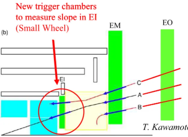
The TGC trigger chambers in the middle endcap station (EM) measure the slope of the muon
tracks. Only tracks pointing closely to the primary vertex are selected for the Level-1 trigger, as-
suming they had undergone only a small deflection in the magnetic field of the endcap toroid. At
the Inner station (EI), however, no measurement of the slope is presently available. The conse-
quences of this deficit for the trigger selectivity are demonstrated in figure 1, where three scenarios
2012 JINST 7 C01048
Figure 1. Three trigger scenarios in the EI station of the Muon spectrometer (“Small Wheel”). Tracks B and C may generate a fake trigger, without the track originating from the primary vertex.
of muon tracks generating triggers are shown: track A corresponds to a valid high-p
Tmuon trig- ger candidate, the small angular deviation from an infinite momentum line being the criterion for high-p
T, while tracks B and C do not come from the interaction point, being either scattered in the calorimeter (C) or having its origin in the down-stream region and being deflected “backwards”
by the toroidal magnet. Obviously, fake triggers of type B and C could be rejected by a precise measurement of the track’s slope in the EI station.
Presently three concepts are considered as candidates for an improved trigger in the EI station:
(a) Thin Gap Chambers (TGC), (b) Resistive Plate Chambers (RPC) and (c) Micromega Chambers (MM), the latter combining precision tracking and triggering capabilities in the same chamber.
All three chamber types are designed to achieve a position resolution accuracy of < 0.2 mm in the radial coordinate η. For precision tracking Small tube MDT chambers and Micromega chambers are under consideration.
The present concept for the upgrade is a complete replacement of the EI stations with new trigger and precision chambers, as presented below.
2 Precision chamber concepts for the endcap of the Muon Spectrometer
2.1 MDT chambers with Small Tubes for tracking at high background rates
The limitations of the MDT precision chambers at high luminosities are mainly due to isolated hits in the tubes (”fake hits”), caused by Compton scattering of gammas which, in turn, come from neutron capture in the material of the chambers and adjacent support material. In the Small Wheel the resulting hit densities strongly increase towards the inside, while, on the other hand, the length of the tubes in the trapezoidal geometry of the Small Wheel decreases proportional to the distance from the beam line (R). Hit densities, however, are increasing considerably faster than with 1/R, and therefore the highest tube hit rates are at the innermost radii of the chambers, as presented in figure 2 (from [4]). The presently used chamber technology (MDT and CSC) will not be able to cope with the background in this region.
Reduction of the drift tube diameter from 30 mm to 15 mm, while keeping the other operat-
ing parameters unchanged, leads to a significant improvement of the rate capability of the drift
2012 JINST 7 C01048
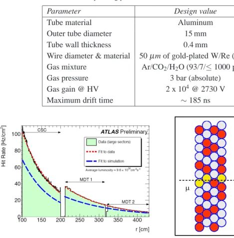
Table 1. The operating parameters of Small Tube MDT chambers.
Parameter Design value
Tube material Aluminum
Outer tube diameter 15 mm
Tube wall thickness 0.4 mm
Wire diameter & material 50 µ m of gold-plated W/Re (97/3) Gas mixture Ar/CO
2/H
2O (93/7/≤ 1000 ppm)
Gas pressure 3 bar (absolute)
Gas gain @ HV 2 x 10
4@ 2730 V
Maximum drift time ∼ 185 ns
Figure 2. Hit rate per cm2 in the Small wheel vs. distance r from the beam line at∼1033cm−2s−1. The change in chamber technology from MDT to CSC at ∼200 cm leads to a change in normalization of∼10%. Simulation slightly underestimates the mea- sured rates.
Figure 3. The tracking quality in 30 mm and 15 mm drift tubes. The occupancies from background hits (red dots) are 50% in the 30 mm tubes but only 7% in the 15 mm tubes due to shorter drift time and smaller area.
tube chambers [5], more than sufficient for their operation in the New Small Wheel (NSW) up to the highest background rates expected at 5 times the LHC design luminosity (see figure 3). To distinguish this chamber concept from the existing MDT, we refer to it as to sMDT chambers.
With the operating parameters given in table 1, the maximum drift time is reduced by a factor of 3.5, i.e. from about 700 ns to < 200 ns [6]. In addition, the background flux, hitting a tube of given length is reduced by a factor of two. Altogether, the drift tube occupancy is reduced by a factor of 7. Using the sMDT concept, the 2×6 drift tube layers at radii R < 2 m and the 2×4 layers at larger radii provide very robust tracking with track segment reconstruction efficiencies above 99 % up to the highest background rates [7].
Table 2 presents the expected tube hit rates, occupancies and efficiencies for the innermost
tubes of the three chamber types in a sector of the NSW. Chamber EIL0 covers the area now taken
by the CSC. The numbers in col. 5 are based on hit rate measurements in ATLAS, at a luminosity
of 9 · 10
32cm
−2s
−1, as shown in figure 2. Rates in the CSC region (1 m < R < 2 m) are measured as
2012 JINST 7 C01048
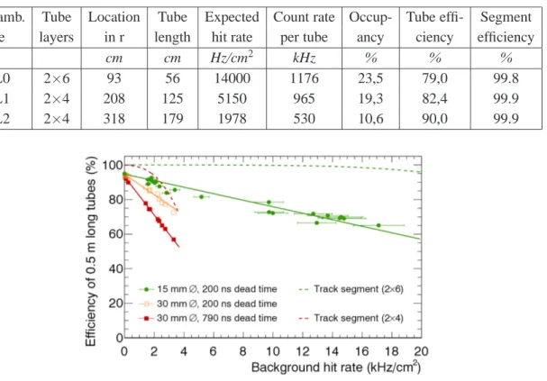
Table 2. Expected hit rates and efficiencies for 15 mm tubes in a sector of the New Small Wheel at a luminosity of 5×nominal (times a factor of 1.4, see text).
Chamb. Tube Location Tube Expected Count rate Occup- Tube effi- Segment type layers in r length hit rate per tube ancy ciency efficiency
cm cm Hz/cm
2kHz % % %
EIL0 2×6 93 56 14000 1176 23,5 79,0 99.8
EIL1 2×4 208 125 5150 965 19,3 82,4 99.9
EIL2 2×4 318 179 1978 530 10,6 90,0 99.9
Figure 4. The efficiency of individual drift tubes as a function of the background hit rate as measured at the Gamma Ray Facility at CERN. Results for 15 mm and 30 mm diameter tubes are compared. The corresponding track segment reconstruction efficiencies in 2×4 layer MDT chambers and 2×6 layer sMDT chambers have been calculated and are indicated as dashed, see text.
well as extrapolated from larger radii, using an exponential law [4]. These rates have been scaled up linearly to 5 · 10
34cm
−2s
−1and, in addition, been multiplied by a safety factor of 1.4, which brings the maximum hit rate expected for a tube in the NSW up to 14 kHz/cm
2. The efficiencies are calculated from exp(-τ ·f) ≈ 1-τ ·f, where τ is the dead time after a hit (we use the maximum drift time of 200 ns) and f the hit rate per tube.
1The segment efficiencies given in column 9 have been calculated from the measured tube efficiencies, requiring at least two hits in each multilayer.
The efficiencies of the sMDT tubes at high rates have been measured at the Gamma Ray Facility (GIF) at CERN, using cosmic rays, see figure 4.
The spatial resolution in a single sMDT tube depends on the distance r of the track from the wire. It varies from 70 µ m close to the tube wall to about 150 µ m close to the wire, with an average of 110 µ m, resulting in a resolution of about 55 µ m for a package of four tubes. Given the lever arm of 150 mm between the centers of the two packages, we obtain an angular resolution of 0.5 mrad.
Unlike in the case of the large tubes, the resolution of the single sMDT tubes degrades little at high background rates, and thus spatial and angular resolution at high background are only reduced to 60 µm and 0.6 mrad, respectively.
1Because of the dead material between the MDT gas volumes (tube walls, glue gap), measured efficiencies will be about 6 % lower than calculated with this formula.
2012 JINST 7 C01048
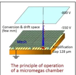
Figure 5. Layout and operating principle of a micromega detector (schematic).
Being able to use the MDT tracking concept at very high background rates allows to preserve the main advantages of the drift tube concept:
(a) Robust pattern recognition and high tracking efficiency up to the expected backround rates.
(b) Excellent position and angular resolution, independent of the angle of incidence onto the chamber plane. This property of drift tube chambers with their circular drift geometry is a decisive advantage over drift chambers with rectangular drift geometry.
(c) High reliability of the chambers, due to operational independence of the drift tubes, any malfunction of an individual tube causing only a negligible inefficiency for the whole system.
The mechanical structure and the alignment system will be as similar as possible to the ones in the present Small Wheel architecture. The readout electronics will follow the proven concept of the existing MDT system (see [8]), adapted to the higher rate requirements. For the proposed layout of the NSW 71000 channels of readout electronics will be required.
2.2 Micromega chambers for tracking at high background rates
Micromega detectors (MM) are thin wireless gaseous detectors. They consist of a planar drift elec- trode, a gas gap of 5 mm thickness, acting as drift region, and a thin metallic mesh at 128 µ m distance from the readout electrode, creating the amplification region, see figure 5. Drift elec- trode and amplification mesh are at negative high voltage potentials, the readout electrode is at ground potential.
The small extent of the MM amplification region allows for a fast evacuation (∼ 100 ns) of the positive ions, which makes MM detectors suited for operation at high particle fluxes. In addition, a much higher immunity to sparking has been achieved by implementing a resistive strip and an insu- lating layer on top of the metallic readout strips. The present status of the MM detector technology is resumed in [9].
The main advantages of MM chambers for an application in the NSW are as follows:
2012 JINST 7 C01048
(a) Excellent performance with respect to spatial resolution and efficiency up to very high rates.
(b) Good time resolution in the range of 2–4 LHC beam crossings (50–100 ns), determined by the drift speed of primary electrons of about 50 mm/µ s and the thickness of the drift gap of 5mm.
(c) Good ageing properties.
(d) Use of the non-flammable Ar/CO
2gas mixture at athmospheric pressure.
(e) Design suited for industrial production, using procedures and quality insurance tools of the printed circuit board industry.
To be used in the NSW, each MM chamber consists of two packages of four detector lay- ers, similar to the MDT arrangement in the present Small Wheel. The pitch of the readout strips along the bending η-direction will be 0.5 mm, while in the φ -direction it will be several mil- limeters. Altogether, two million readout channels will be required for the whole system of two wheels. The expected position resolution along η will be about 50 µ m, using charge interpolation between strips.
The readout of the strips will be accomplished by ASICs servicing 64 channels. The ASICs are presently under development. They also provide a timing measurement of the first arriving signal among the 64 channels, which is essential for the use of the MM information in the Level-1 trigger. More details about the L1-trigger strategy, using MM information are given in 3.3.
3 Trigger chamber concepts for the endcap of the Muon Spectrometer
3.1 Combined TGC plus sMDT chambers for the Inner Station of the endcap
A detailed presentation of the TGC technology, as used in the Muon sprectrometer endcap is given in [3]. This technology has been adapted to the requirements of higher spatial resolution and rate capability by a finer segmentation of the pickup strips and by a low resistivity of the cathodes planes in the gas gaps. This new chamber type is referred to as sTGC.
Figure 6 shows the concept of combining sTGC trigger and sMDT precision chambers in the new EI station. Two sMDT units with 4 or 6 tube layers each, as described in section 2.1, are enclosed by two packages of sTGCs. Each sTGC package consists of four gas volumes with wires in radial direction, at about 6 mm spacing, grouped appropriately to give the required granularity for φ readout. Among the two cathode planes of each gas volume, one is equipped with pick-up strips, perpendicular to the wires, measuring η, with a pitch of 3.5 mm, the other one is segmented in square pads with a side length of 7 to 25 cm, depending on R, arranged in projective towers along the eight chamber layers. A 3-out-of-4 coincidence of the pads in a tower is used to produce a coarse Region of Interest (RoI) for the Level-1 trigger logic. The pads are also used offline to resolve ambiguities when a chamber contains more than one track.
The required position resolution is obtained by a convolution of the pulse heights on adjacent
strips, giving the centroid of the charge distribution. Test beam results have shown that the pulse
heights obtained from a time-over-threshold (ToT) measurement, combined with a convolution
methode to find the charge centroid yields the position of the track with an accuracy of ∼ 60 µ m.
2012 JINST 7 C01048
Figure 6. Cross section through the proposed arrangement of trigger sTGCs and precision sMDTs. The sMDT, made out of two packages of 4 or 6 tube layers each, is sandwiched between two packages of 4- layer sTGCs.
In the next step of trigger formation the reconstructed hit positions are combined (after possibly removing spoiled hits
2), to produce a unique track position in the package. Subsequently, the track positions in the two packages are combined to determine the slope. Finally, a test is made on whether the track points to the interaction point with sufficient accuracy. The result is transferred to the Sector Logic (SL) in USA15, where the trigger decision is made by combining the information from both trigger stations, EI and EM.
3Precise knowledge of the latency is mandatory for the first phase of the LHC upgrade, as during this period the maximum Level-1 latency in ATLAS must be below 2.55 µ s, counted from the beam crossing to the arrival of the Level-1 trigger at the frontend of the detector electronics.
For the sTGC trigger this means that the signals from the chamber frontend must arrive at the input of the Sector Logic not later than 1.05 µs after the collision at the interaction point. Present estimates for the latency of the sTGC trigger lead to 0.9 µ s, leaving a safety margin of about 150 ns.
A demonstrator of the envisaged readout electronics, using commercial components, is currently implemented in order to perform a detailed evaluation of the resulting trigger latency.
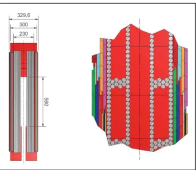
3.2 Combined RPC plus sMDT chambers for the Inner Station of the endcap
A detailed presentation of the RPC technology, as used in the Muon sprectrometer barrel is given in [3]. A number of design changes has been made to adapt the RPC technology to the high rate environment of the endcap: the gas gap has been reduced from 2 to 1 mm, reducing the high voltage applied to the gap and the charge released in each hit. In addition, the strip pitch has been reduced
2Hits may be spoiled byδ rays or neutron conversions, both leading to a wider signal distribution across the strips than is expected for a single minimum ionising particle.
3The Outer Endcap station (EO) does not contribute to the trigger, containing only MDT precision chambers.
2012 JINST 7 C01048
Figure 7. Cross section through the proposed ar- rangement of trigger RPCs and precision sMDTs.
The distance of 280 mm between the RPC pack- ages (center-to-center) is instrumental for the an- gular resolution of the triggering muon track.
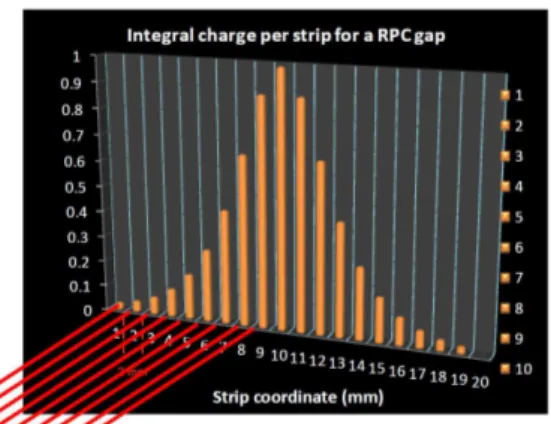
Figure 8. Simulated charge distribution on the pick-up strips of a RPC with ∼2 mm readout pitch. A convolution of the pulseheights above threshold yields the position of the track with a
∼0.2 mm accurancy.
by an order of magnitude to 3.5 mm and charge interpolation is used to obtain a position resolution of about 0.2 mm. A particular feature of the RPC design is the inherent, sub-nanosecond time resolution, which can be used to select “prompt” muons, coming directly from the IP, discarding a large fraction of the background hits due to their late arrival. This new type of RPC is called mini-gap RPC (mRPC).
A similar chamber arrangement like the one given in figure 6 can be implemented by com- bining mRPCs with sMDTs (figure 7). Again, two sMDT units with 6 or 4 tube layers each are sandwiched between two packages of trigger chambers, each having three mRPC gas gaps. Each gas gap has pick-up strips in η and φ with 1–2 mm and a few cm spacing, respectively. Signals are combined to form 2-out-of-3 coincidences in a similar way like in the case of the sTGC. The signal amplitudes on the strips will have a distribution as illustrated in figure 8. A convolution delivers the charge centroid with an accuracy of ∼ 0.2 mm.
3.3 The Level-1 trigger function of the micromega chambers
The high position resolution of the micromega chambers (MM) combined with good time resolu- tion allow for a combination of the precision tracking and trigger function in the same chamber.
The fast recognition of a (straight) high-p
Ttrack, coming from the primary vertex will be based
on a coincidence scheme among wire groups of 64, corresponding to the 64-fold modularity of the
frontend chip. A valid Level-1 candidate will fulfill a 3-out-of-4 coincidences in both MM pack-
ages along a line pointing to the primary vertex. The coordinates of the non-zero readout strips
in the triggering 64 strip groups will then be used to determine the exact angle of the track with
respect to the primary vertex. A detailed simulation of this trigger strategy in the presence of the
cavern background is presently in preparation.
2012 JINST 7 C01048
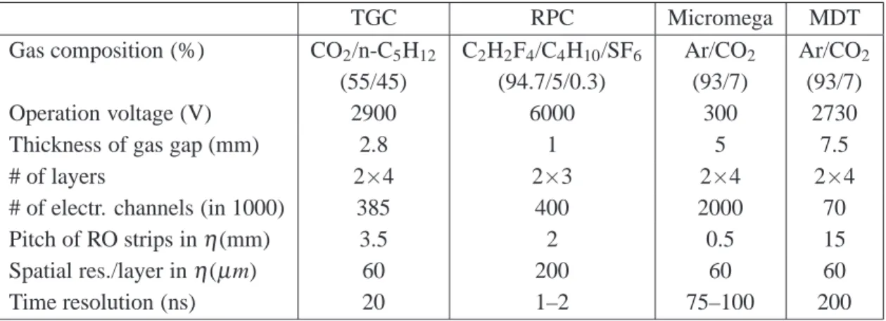
Table 3. Preliminiary operating and performance parameters for the three trigger and two precision chamber concepts, proposed for the NSW of the ATLAS muon spectrometer.
TGC RPC Micromega MDT
Gas composition (%) CO
2/n-C
5H
12C
2H
2F
4/C
4H
10/SF
6Ar/CO
2Ar/CO
2(55/45) (94.7/5/0.3) (93/7) (93/7)
Operation voltage (V) 2900 6000 300 2730
Thickness of gas gap (mm) 2.8 1 5 7.5
# of layers 2×4 2×3 2×4 2×4
# of electr. channels (in 1000) 385 400 2000 70
Pitch of RO strips in η (mm) 3.5 2 0.5 15
Spatial res./layer in η ( µ m) 60 200 60 60
Time resolution (ns) 20 1–2 75–100 200
3.4 Comparision of the proposed chamber concepts
Table 3 presents the main operating and performance parameters of the four proposed chamber systems. The TGC and RPC are proposed to operate together with MDT chambers, which means two separate technologies, complementary with respect to time and spatial resolution, while the MM concept aims to unify triggering and precision tracking in one technology.
Tests on rate capabilities, spatial resolution and ageing properties are in an advanced state.
Details of design and implementation of the readout electronics are under study, and prototypes of crucial ASICs will soon be released for production. Questions of series production in cooperation with industry, respecting the tight quality criteria, are also addressed.
4 Summary
The upgrade of the LHC towards five times the original target luminosity of 10
34cm
−2s
−1calls for a complete replacement of the Inner muon station of the ATLAS endcap (“Small Wheel”) as Level-1 trigger rates in the present system will exceed acceptable levels by a large factor, and the tracking efficiency of precision chambers will suffer from high occupancies from γ and n back- ground. Due to the availibility of recently developed concepts for trigger as well as tracking cham- bers, the requirements of the SLHC upgrade can be matched. Concerning trigger chambers, all proposed concepts provide improvements of the spatial resolution by more than an order of mag- nitude, improving the pointing accuracy of tracks towards the primary vertex to below 1 mrad.
Concerning precision tracking, Small tube MDT and Micromega chambers will be able to provide robust tracking up to the highests background rates, due to the small size of the detecting elements, i.e. tube diameter and cathode strip spacing, respectively. All systems, however, face the challenge of developing new high rate readout electronics on the time scale of phase I of the LHC upgrade.
References
[1] J. Dubbert et al. Upgrade of the ATLAS Muon Trigger for the SLHC,2010 JINST 5 C12016.
2012 JINST 7 C01048
[2] ATLAS collaboration, Technical design report for the ATLAS Muon Spectrometer, CERN-LHCC-97-22 (1997).
[3] ATLAS collaboration, The ATLAS experiment at the CERN Large Hadron Collider, 2008 JINST 3 S08003.
[4] ATLAS collaboration, L. Jeanty et al., ATLAS: data and MC comparisions for Muon Spectrometer, including Cavern Background, talk given at the LPCC Simulation Workshop, October 6–7, CERN, Switzerland (2011).
[5] B. Bittner et al., Development of precision muon drift tube detectors for the high-luminosity upgrade of the LHC,Nucl. Phys. Proc. Suppl. B 215 (2011) 143.
[6] B. Bittner et al., Development of muon drift-tube detectors for high-luminosity upgrades of the Large Hadron Collider,Nucl. Instrum. Meth. A 617 (2010) 169.
[7] B. Bittner et al., Development of fast high-resolution muon drift-tube detectors for high counting rates, Nucl. Instrum. Meth. A 628 (2011) 154.
[8] Y. Arai et al., ATLAS Muon Drift Tube electronics,2008 JINST 3 P09001.
[9] T. Alexopoulo et al., A spark-resistant bulk-micromegas chamber for high-rate applications, Nucl. Instrum. Meth. A 640 (2011) 110.