Trivial and inverted Dirac bands and the emergence of quantum spin Hall states in graphene on transition-metal dichalcogenides
Martin Gmitra, Denis Kochan, Petra H¨ogl, and Jaroslav Fabian
Institute for Theoretical Physics, University of Regensburg, 93040 Regensburg, Germany (Received 1 October 2015; revised manuscript received 22 February 2016; published 5 April 2016) Proximity orbital and spin-orbital effects of graphene on monolayer transition-metal dichalcogenides (TMDCs) are investigated from first-principles. The Dirac band structure of graphene is found to lie within the semiconducting gap of TMDCs for sulfides and selenides, while it merges with the valence band for tellurides. In the former case, the proximity-induced staggered potential gaps and spin-orbit couplings (all on the meV scale) of the Dirac electrons are established by fitting to a phenomenological effective Hamiltonian. While graphene on MoS2, MoSe2, and WS2has a topologically trivial band structure, graphene on WSe2exhibits inverted bands.
Using a realistic tight-binding model we find topologically protected helical edge states for graphene zigzag nanoribbons on WSe2, demonstrating the quantum spin Hall effect. This model also features “half-topological states,” which are protected against time-reversal disorder on one edge only.
DOI:10.1103/PhysRevB.93.155104
I. INTRODUCTION
There has recently been a strong push to find ways to enhance spin-orbit coupling in graphene [1] to enable spin- tronics applications [2,3]. Decorating graphene with adatoms [4,5] has proven particularly promising, as demonstrated experimentally by the giant spin Hall effect signals [6,7]. In parallel, there have been intensive efforts to predict realistic graphene structures that would exhibit the quantum spin (and anomalous) Hall effect [8–11], introduced by Kane and Mele [12] as a precursor of topological insulators [13–15].
Ideal for inducing a large proximity spin-orbit coupling in graphene would be a matching two-dimensional insulating or semiconducting material to preserve the Dirac band structure at the Fermi level. Hexagonal BN is a nice substrate for graphene, but it has a weak spin-orbit coupling itself [1], so the proximity effect is negligible. The next best candidates are two-dimensional transition-metal dichalcogenides (TMDCs) which are direct band-gap semiconductors [16,17]. Graphene on TMDCs has already been grown [18–20] and investigated for transport [21,22] as well as considered for technological applications [23–26]. It was recently predicted that monolayer MoS2 will induce a giant spin-orbit coupling in graphene, of about 1 meV (compared to 10μeV in pristine graphene [27]). A recent experiment [7] on the room-temperature spin Hall effect in graphene on few layers of WS2 found a large spin-orbit coupling, about 17 meV, attributing it to defects in the thin WS2, rather than to the genuine proximity effect.
As the proximity spin-orbit coupling in graphene on TMDCs is expected to grow with the increasing atomic number of the transition metals, we here explore the whole family of TMDCs as potential substrates for graphene. In most cases, we find trivial Dirac cones, affected by the proximity effects.
But for graphene on WSe2 we see a robust band inversion and emergent spin Hall effect in the corresponding zigzag nanoribbons.
More specifically, we report here on systematic first- principles calculations predicting that (i) graphene on MoS2, WS2, MoSe2, WSe2, MoTe2, and WTe2 monolayers [see Fig.1(a)for the structure] preserves its linear-in-momentum band structure within the TMDCs direct band gaps, shifting
the Dirac point towards the valence bands of TMDCs with increasing the atomic number of the chalcogen; graphene on transition-metal tellurides has the Dirac point merged with the TMDCs valence bands. (ii) The proximity spin-orbit coupling increases with the atomic number of the transition metal.
While the Dirac band structure in most cases is conventional, (iii) graphene on WSe2 exhibits a band inversion due to the anticrossings of graphene’s conduction and valence bands that are spin polarized in the opposite directions. The evolution of the graphene band structure from pristine, through trivial proximity, and to nontrivial band inversion, as the proximity spin-orbit coupling increases, is sketched in Fig.1(b). Using realistic tight-binding modeling of the proximity-induced orbital and spin-orbital effects in graphene on WSe2, we further show that (iv) zigzag graphene nanoribbons in this structure have helical edge states inside the bulk gap, demonstrating the quantum spin Hall effect. We also find that (v) states outside the gap exhibit a pronounced edge asymmetry, with an odd number of pairs at one edge and even number of pairs at the other edge. We call such states half-topological, as they are protected against time-reversal impurity scattering at one edge only.
II. RESULTS
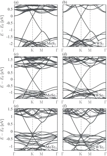
A. Survey ofab initioband structures of graphene on TMDCs To calculate the electronic structure of graphene on TMDCs we applied density functional theory, coded in QUANTUM ESPRESSO[28], on a supercell structural model to reduce strain due to the incommensurate lattice constants of graphene and TMDCs; see Appendix A for computational details. Such quasicommensurate superstructures of TMDCs have been grown on HOPG [29]. In Fig.2, we show the calculated band structures of graphene on monolayer MoS2, WS2, MoSe2, WSe2, MoTe2, and WTe2 along high-symmetry lines. In the case of sulfur and selenium based TMDCs, we find linear dispersive states of graphene with the Dirac cone within the direct gap of TMDCs. As the atomic number of the chalcogen increases, the Dirac cone shifts down towards the valence band edge of TMDCs. In tellurides the Dirac point moves below the
FIG. 1. Sketch of (a) the atomic structure of graphene on a monolayer transition-metal dichalcogenide, and (b) evolution of spin-orbit coupling induced band structure topology near the Dirac point of graphene in this hybrid structure. In the absence of spin-orbit coupling the doubly spin degenerate bands are split by the proximity orbital gap. As the proximity spin-orbit coupling is turned on, first the spin degeneracy is lifted, followed by the band inversion at large values of spin-orbit coupling. Red and blue colors indicate the opposite spin projections along the transverse (z) axis.
valence band edge and the graphene bands there get strongly distorted.
In the following, we study in detail the electronic states of the well-preserved Dirac band structures of graphene on sulfides and selenides. Essential calculated orbital electronic properties, such as the valence and conduction band offsets Ev and Ec, the induced dipole moment (which points towards graphene) of the double-layer structures, and the work functionsW of the graphene and TMDC layers (calculated as the difference between the self-consistent electrical potential just outside of the layer and the Fermi level of the whole system), are listed in Table I. We also found that the band offsets can be controlled by an applied transverse electric field (see AppendixC). For example, we predict the possibility to tune graphene on WSe2by gates to reach amassless-massive electron-holeregime.
B. Dirac band structure topologies
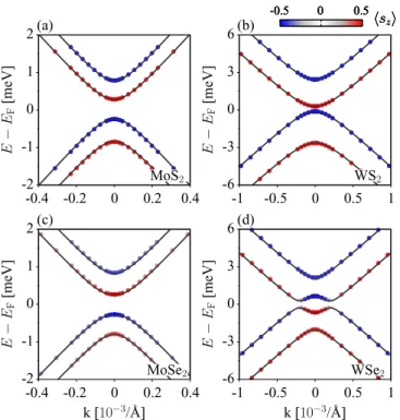
We now look at the band structure topologies of the Dirac cones modified by the proximity effects. Electronic transport in those heterostructures will be graphenelike, with the proximity-induced fine topological features which depend on the TMDC material. A zoom into the Dirac cone for the four selected heterostructures is shown in Fig.3. Three materials, graphene on MoS2, WS2, and MoSe2, share the same topology, studied already in the MoS2 case in Ref. [30]. The essential features are (a) opening of an orbital gap due to the effective
-1 -0.5 0 0.5 1 1.5
Γ K M Γ
E−EF[eV]
-1 -0.5 0 0.5 1 1.5
Γ K M Γ
E−EF[eV]
-2 -1.5 -1 -0.5 0 0.5
Γ K M Γ
E−EF[eV]
Γ K M Γ
Γ K M Γ
Γ K M Γ
MoTe2 (e)
MoSe2 (c)
MoS2 (a)
WTe2 (f)
WSe2 (d)
WS2 (b)
FIG. 2. Calculated electronic band structures along high- symmetry lines for graphene/TMDC heterostructures: (a) MoS2, (b) WS2, (c) MoSe2, (d) WSe2, (e) MoTe2, and (f) WTe2.
staggered potential (on average, atoms A and B in the graphene supercell see a different environment coming from the TMDC layer), (b) anticrossing of the bands due to the intrinsic spin-orbit coupling, and (c) spin splittings of the bands due to spin-orbit coupling and breaking of the space inversion symmetry. Both the orbital gap and spin-orbit couplings are on the meV scales, which are giant compared to the 10μeV spin-orbit splitting in pristine graphene [27]. In Fig.3, we also show the spin character of the bands around K. We find that TABLE I. Calculated energy offsets, dipole moments, work functions and tight-binding model orbital and spin-orbital parameters for graphene/TMDC heterostructures. Labels:EvandEcare the TMDCs valence and conduction band offsets with respect to graphene’s Dirac point, “dipole” is the dipole moment,WgrpandWTMDCare the work functions of graphene and TMDCs,vFis the Fermi velocity andtis the associated nearest neighbor hopping energy of graphene’spzelectrons in the presence of TMDC,is the induced orbital staggered potential of graphene,λAI andλBI are the intrinsic spin-orbit couplings for A and B graphene sublattices,λRis the Rashba spin-orbit coupling, andλAPIA andλBPIAare the pseudospin-inversion-asymmetry (PIA) spin-orbit terms for the two sublattices.
Ev Ec dipole Wgrp WTMDC vF/105 t λAI λBI λR λAPIA λBPIA
TMDC (eV) (eV) (Debye) (eV) (eV) (m/s) (eV) (meV) (meV) (meV) (meV) (meV) (meV)
MoS2 1.51 0.04 0.628 4.12 4.407 8.506 2.668 0.52 −0.23 0.28 0.13 −1.22 −2.23
MoSe2 0.56 0.92 0.624 4.3 4.577 8.223 2.526 0.44 −0.19 0.16 0.26 2.46 3.52
WS2 1.13 0.30 0.675 4.12 4.432 8.463 2.657 1.31 −1.02 1.21 0.36 −0.98 −3.81
WSe2 0.22 1.15 0.641 4.3 4.587 8.156 2.507 0.54 −1.22 1.16 0.56 −2.69 −2.54
-2 -1 0 1 2
-0.4 -0.2 0 0.2 0.4 E−EF[meV]
k [10−3/Å]
-2 -1 0 1 2
-0.4 -0.2 0 0.2 0.4 E−EF[meV]
-6 -3 0 3 6
-1 -0.5 0 0.5 1
E−EF[meV]
k [10−3/Å]
-6 -3 0 3 6
-1 -0.5 0 0.5 1
E−EF[meV]
-0.5 0 0.5
sz
MoSe2 (c)
-0.5 0 0.5
sz
MoS2 (a)
-0.5 0 0.5
sz
WSe2 (d)
-0.5 0 0.5
sz
WS2 (b)
FIG. 3. Calculated electronic band structures in the vicinity of the Dirac point for graphene/TMDC heterostructures: (a) MoS2, (b) WS2, (c) MoSe2, and (d) WSe2. The solid lines are model fits, while the circles are first-principles data. Colors code thezcomponent of the spin expectation value.
the valence states are formed at the B sublattice while the conduction states live on A. The same orbital ordering is at K. The spin alternates as we go through the bands. At Kthe spin orientation is opposite.
The case of graphene on WSe2stands out. Figure3shows an inverted band structure, which is the main focus of our paper, as it is an indication for a nontrivial topological ordering. While far from K the band ordering in the Dirac band structure of WSe2looks the same as in the other three cases, close to K the two lowest energy bands anticross. The top of the valence band and the bottom of the conduction band have opposite spins to the rest of the states of the same bands.
C. Effective Hamiltonian
Both the trivial and nontrivial topologies observed in Fig.3 can be modeled with the same effective Hamiltonian acting on graphenepzorbitals, introduced in Ref. [30] for graphene on MoS2. The HamiltonianH =Horb+Hso has orbital and spin-orbital parts. The orbital part, describing gapped Dirac states, is
Horb=vF(κσxkx+σyky)+ σz, (1) where vF is the Fermi velocity of Dirac electrons, is the staggered potential (gap),σ are the pseudospin Pauli matrices operating on the sublattice A and B space, andkxandkyare the Cartesian components of the electron wave vector measured from K (K); parameterκ =1 (−1) for K (K).
The spin-orbit Hamiltonian Hso=HI+HR+HPIA has three components: intrinsic, Rashba, and PIA (short for pseudospin inversion asymmetry [5]). Since both intrinsic and
PIA are second-nearest-neighbor hoppings [31], they can be different for the two sublattices. We have
HI= 1 2
λAI(σz+σ0)+λBI(σz−σ0)
κsz, (2) HR=λR(κσxsy−σysx), (3) HPIA=a
2
λAPIA(σz+σ0)+λBPIA(σz−σ0)
(kxsy−kysx). (4) Here,λAI and λBI are the intrinsic spin-orbit parameters for sublattices A and B,λRis the strength of the Rashba coupling, andλAPIAandλBPIAare the PIA spin-orbit parameters;sdenotes the spin Pauli matrices, anda =2.46 ˚A is the pristine graphene lattice constant.
By solving the spectrum ofH around K and comparing with theab initioresults, considering the sublattice character of the states as well as their spin projections, we can uniquely determine the orbital and spin-orbital parameters. They are listed in TableI. The perfect agreement between the effective model and theab initio calculations, for all four materials, is evident from Fig. 3. Both the orbital and spin-orbital parameters can be tuned by a transverse electric field and vertical strain. Only in the case of graphene on WSe2 the orbital gapis smaller than the magnitudes of the intrinsic spin-orbit coupling parametersλI. This is a signature of the inverted band structure seen in Fig.3.
D. Quantum spin Hall effect in graphene on WSe2
The inverted band structure is a precursor of the quantum spin Hall effect (QSHE). Although zigzag graphene nanorib- bons were predicted to host helical edge states [12],intrinsic spin-orbit coupling in graphene is too weak [27] for such states to be experimentally realized. Instead, 2d(Hg,Cd)Te quantum wells have emerged as a prototypical quantum spin Hall system [13–15].
Our first-principles results strongly suggest that graphene on WSe2, with the inverted Dirac bands due to the strong proximity (100 times stronger than in pristine graphene) spin-orbit coupling, acts as a quantum spin Hall insulator.
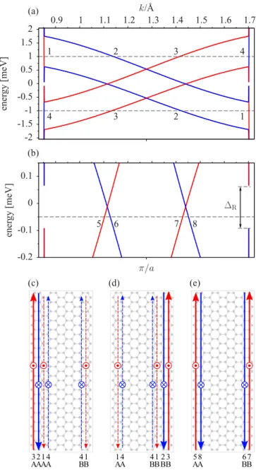
In bulk, graphene on monolayer WSe2 experiences a gap, making it an insulator (see Fig.3). This behavior is robust against an applied transverse electric field and vertical strain (see Appendix C). To demonstrate the presence of helical edge states we have converted our effective HamiltonianH into a tight-binding model (see Appendix D), following an earlier work on hydrogenated graphene [5], and analyzed the energy spectra and states of zigzag nanoribbons of graphene on TMDCs. The results for graphene on WSe2are shown in Fig.4, for a nanoribbon of size 200 nm. The band structure features spin-split bands due to spin-orbit coupling, with four bands crossing the Fermi level. The bulk gap is transformed to what we term the Rashba anticrossing gapR. This gap increases with the nanoribbon width as well as with the Rashba coupling, saturating at the bulk level. More details on the Rashba anticrossing, including perturbative analytical estimates, are presented in AppendixF, where we also discuss the offset of the edge-state energies from the bulk states of the nanoribbon.
-2 -1.5 -1 -0.5 0 0.5 1 1.5
2 0.9 1 1.1 1.2 1.3 1.4 1.5 1.6 1.7
energy[meV]
k/Å
4 3
2 1
1 2
3 4
(a)
(b)
(c) (d) (e)
-0.2 -0.1 0 0.1
π/a
energy[meV]
5 6 7 8
ΔR
FIG. 4. Calculated electronic structure of a zigzag graphene nanoribbon on WSe2, with the width of 200 nm. (a) Electronic states with spin up (red) and spin down (blue). Labels 1–4 denote states whose localization and sublattice characters are described in (c)–(e). (b) Zoom to the spin-polarized states 5–8 within the Rashba anticrossing gapR. (c) Sketch of the helical states for energy 1 meV with the labels for spatial and sublattice localization, as well spin up and spin down⊗character. In-plane vertical up (down) arrows indicate positive (negative) group velocities. The dashed lines stand for states localized on both edges. (d) Sketch of the helical states for energy−1 meV. (e) Sketch of the helical states for energy−0.05 meV inside the Rashba anticrossing gap.
Already the states above the Rashba anticrossing gap are peculiar. In Fig. 4, we indicate the states 1–4 at a positive energy of 1 meV. States 1 and 4 are spin polarized, but localized on both edges. However, states 2 and 3 are helical, but localized on one edge only! These edge states have a fixed pseudospin character, as shown in the figure. The asymmetry in the edge localization makes the states 1 and 4 topologically protected against scattering by time-reversal impurities at one
edge only. At the other edge, backscattering is possible due to the presence of another pair of helical states. We call such states half-topological. With increasing width of the ribbons, states 1 and 4 become more delocalized, eventually becoming bulk states; helical states 2 and 3 stay localized at one edge.
At negative energies, the asymmetry of the edge states gets reversed (see Fig.4).
The helical states defining the quantum spin Hall effect live within the Rashba anticrossing gapR. For example, states 5–8 in Fig.4(e)are spin-polarized edge states localized on a specific sublattice as indicated. These states are topologically protected against backscattering by time-reversal impurities. If the model parameters are used for graphene on MoS2, MoSe2, and WS2, which have trivial Dirac bulk bands (see Fig. 3), zigzag nanoribbons remain insulating, featuring no helical edge states.
III. CONCLUSIONS
In summary, we have made a detailed study of the electronic states and the proximity spin-orbit coupling in graphene on monolayer transition-metal dichalcogenides. We have found that graphene on WSe2 exhibits a band inversion due to spin-orbit coupling which gives rise to helical edge states in graphene nanoribbons on WSe2.
Note added.Recently, we learned that Wanget al.[32] pre- dict a QSHE in graphene on WS2, but for larger superlattices in which the staggered potential diminishes. For superlattices as ours, the bands are normal for realistic van der Waals distances [32], in agreement with our results. In contrast, graphene on WSe2exhibits inverted bands already for smaller superlattices (but also for larger, see AppendixC), making this effect more robust.
ACKNOWLEDGMENT
This work was supported by DFG SFB 689, GRK 1570, International Doctorate Program Topological Insulators of the Elite Network of Bavaria, and by the EU Seventh Framework Programme under Grant Agreement No. 604391 Graphene Flagship.
APPENDIX A: COMPUTATIONAL METHODS Structural relaxation and electronic structure calculations were performed within density functional theory (DFT) employing QUANTUM ESPRESSO package [28], using norm- conserving pseudopotentials with kinetic energy cutoff of 60 Ry for wave functions. For the exchange-correlation potential we used the generalized gradient approximation [33]. To model graphene on transition-metal dichalcogenide (TMDC) we consider a structural model containing a 4×4 supercell of graphene and a 3×3 supercell of TMDC (see Fig.5). The residual lattice mismatch is split equally between graphene and TMDC. In TableII, we give the lattice constants for TMDC and the residual lateral strain for graphene. The supercell has 59 atoms. The reduced Brillouin zone was sampled with 12×12kpoints. The atomic positions were relaxed using the quasi-Newton algorithm based on the trust radius procedure including the van der Waals interaction which was treated
FIG. 5. Top view of the structural model of graphene on TMDC used in the DFT calculations. The model contains a 4×4 supercell of graphene and a 3×3 supercell of TMDC. Carbon atoms are dark gray, metal atoms are green, and chalcogen atoms are yellow.
within a semiempirical approach [34,35]. Typical graphene TMDC interlayer distance is of van der Waals order 3.3–3.4 ˚A.
The average graphene surface corrugation calculated from the standard deviation is listed in TableII.
The supercell was embedded in a slab geometry with vacuum of about 13 ˚A. We applied the dipole correction [36], which turned out to be crucial to get the numerically accurate Dirac point offsets within TMDC band gap (see TableI).
APPENDIX B: SPIN SPLITTING AWAY FROM K FOR GRAPHENE ON MONOLAYER WSe2
The pseudospin inversion asymmetry spin-orbit coupling (PIA) is not present directly at K. Away from K, PIA introduces a momentum modulation of the spin splitting. In Fig. 6, we plot the calculated spin splittings of the valence and conduction bands of graphene on WSe2. The full effective model Hamiltonian H, with PIA, fits the first-principles data perfectly. The fits give λAPIA= −2.69 meV andλBPIA=
−2.54 meV. The fitting values, also for other TMDCs, are presented in TableI.
TABLE II. Structural properties of graphene/TMDC heterostruc- tures used in the DFT calculations (cf. Fig.5). We give the lattice constant a of TMDC, the lateral strain of graphene with respect to the unstrained value for the lattice constant of 2.46 ˚A, and the average surface corrugation of graphene calculated from the standard deviation.
a Strain Corrugation
TMDC ( ˚A) (%) (pm)
MoS2 3.231 −1.5 3.1
MoSe2 3.299 +0.6 2.2
WS2 3.228 −1.6 4.5
WSe2 3.297 +0.5 1.8
MoTe2 3.407 +3.9 1.1
WTe2 3.405 +3.8 1.2
1.2 1.6 2 2.4 2.8
0 0.25 0.5 0.75 1
splitting[meV]
k [10−3/Å]
conduction band valence band fit
FIG. 6. Spin splitting away from K (k=0), in the direction of, modulated by PIA spin-orbit coupling in graphene on WSe2. Solid lines are model fits, symbols are first-principles results.
APPENDIX C: EFFECTS OF TRANSVERSE ELECTRIC FIELD, VERTICAL STRAIN, AND HORIZONTAL MISALIGNMENT OF GRAPHENE ON MONOLAYER
WSe2, SUPERCELL SIZE: ROBUSTNESS OF THE BAND INVERSION
Here, we investigate the influence of an applied transverse electric field and vertical strain and horizontal misalignment on the orbital and spin-orbital parameters for graphene on monolayer WSe2, entering our model HamiltonianH.
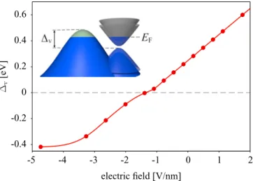
The electric field is included self-consistently on the DFT level. We denote as positive electric fields those pointing from WSe2to graphene. Negative fields move the Dirac cone towards the valence band edge of WSe2. In Fig.7, we plot the band offsetv, which is the difference between the valence band maximum of graphene and WSe2, as a function of the electric field. For the fields below−1.4 V/nm graphene gets n doped while WSe2 gets p doped. This creates a mixed
-0.4 -0.2 0 0.2 0.4 0.6
-5 -4 -3 -2 -1 0 1 2
Δv[eV]
electric field [V/nm]
FIG. 7. Calculated offsetvfrom the valence band maximum of graphene to WSe2, as a function of an applied transverse electric field.
At negative fields, electrons are transferred from WSe2to graphene, establishing a massless-massive electron-hole bilayer.
0.5 0.6
Δ[meV]
(a)
1 1.1 1.2 1.3
−λAI [meV]
λBI[meV]
(b)
0.4 0.5 0.6 0.7 0.8
-2 -1 0 1 2
λR [meV]
electric field [V/nm]
(c)
-6 -4 -2 0
-2 -1 0 1 2
λPIAA
[meV]
λBPIA [meV]
(d)
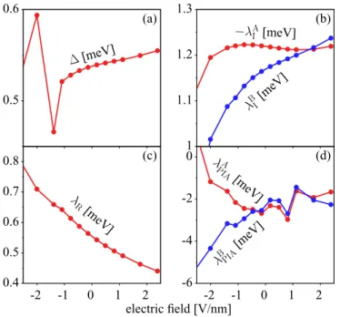
FIG. 8. Calculated effective Hamiltonian parameters as a function of transverse electric field for graphene on WSe2. (a) Hybridization gap; (b) sublattice resolved intrinsic spin-orbit couplingsλAI and λBI; (c) Rashba parameterλR; (d) pseudospin inversion asymmetry parametersλAPIAandλBPIA.
massless-massive electron-holesystem similar to graphene on MoS2observed for positive fields [30].
The effects of the electric field on the Hamiltonian parame- ters are shown in Fig.8. The orbital gapdoes not appreciably change with the field, and similarly the intrinsic spin-orbit couplingsλI, which change at most by 20% in the investigated range of the fields. The Rashba coupling exhibits a monotonic decay as the electric field increases, changing from 0.8 meV at −2.5 V/nm to 0.45 meV at 2.5 V/nm. This decrease is appreciable, demonstrating that the Rashba coupling can be strongly influenced by the field. The effects on PIA are significant at negative electric fields only. The origin of the observed dependencies is not obvious. We present them here to show the tunability of the spin-orbit properties. However, at all the investigated field strengths, graphene on monolayer WSe2exhibits the band inversion (this we checked explicitly, but one can also see this by observing that is less than the magnitudes of λI), demonstrating its robustness against electric fields, but also the absence of a possible tunability of the quantum spin Hall effect.
Vertical strain is introduced by changing the interlayer distance between graphene and WSe2, with respect to the relaxed structure, which is the zero reference strain. Positive (negative) values of strain correspond to decreased (increased) interlayer distance. We observe that as the distance between the two layers decreases (strain increases from negative to positive), the effective model parameters at the K point monotonically increase, with the exception of PIA (see Fig.9).
The increase of the parameters comes from the increased proximity effects. It is not clear why PIA parameters do not change much in the investigated regime of strain. But, the message, again, is that the band inversion is present for all values of the investigated strain, making it robust.
0.4 0.6 0.8 1
Δ[meV]
(a)
0.8 1 1.2 1.4 1.6 1.8 2
−λAI[meV]
λBI[meV]
(b)
0.4 0.6 0.8
-4 -2 0 2 4
λR[meV]
vertical strain [%]
(c)
-3 -2.8 -2.6 -2.4 -2.2
-4 -2 0 2 4
λPIAA
[meV]
λPIAB
[meV]
(d)
FIG. 9. Calculated effective Hamiltonian parameters as in Fig.8 but as a function of vertical strain.
We also investigate the effects of the horizontal misalign- ment of graphene on WSe2 on the inverted band structure.
In Fig.10, we show three horizontal shifts along half of the reciprocal lattice vectors of pristine graphene with respect to WSe2. For all three cases, we extracted model parameters which are listed in TableIII. The explicit check of the low- energy spectra confirmed the presence of the band inversion in all three cases.
Finally, we also consider a larger supercell of 4×4 WSe2
and 5×5 graphene. In this case, the induced strain with respect to the experimental lattice constants is rather large, of about 6%. Even in this case, for a relaxed, typical van der Waals distance of about 3.3 ˚A from WSe2, the band structure exhibits the band inversion [see Fig.11(a)]. In Fig.11(b), we plot the band splitting with the model fits shown with solid lines. The fitting provides the following parameters: =0.244 meV, λAI = −0.645 meV, λBI =0.431 meV, λR=0.56 meV, and λAPIA=9.82 meV,λBPIA= −0.14 meV.
FIG. 10. Structural models for different horizontal shifts of graphene on WSe2.
TABLE III. Calculated model parameters for different horizontal shifts shown in Fig.10.
Shift (meV) λAI (meV) λBI (meV) λR(meV)
(a) 0.442 −1.108 1.091 0.518
(b) 0.432 −1.109 1.095 0.518
(c) 0.543 −1.214 1.164 0.563
We conclude that neither an applied transverse electric field, nor a vertical strain changing the distance of the layers, nor the supercell size considered here, affect the band inversion predicted for graphene on monolayer WSe2.
APPENDIX D: EFFECTIVE TIGHT-BINDING HAMILTONIAN FOR GRAPHENE ON MONOLAYER
TMDCS
In the paper we find that the first-principles Dirac band structure of graphene on TMDCs can be modeled by an effective HamiltonianH acting on the graphene pseudospin and spin spaces only, for a given K (K). Although the pseudospin symmetry is broken only implicitly, and each carbon atom in the supercell feels a different local envi- ronment, this mapping of the DFT results on an effec- tive pseudospin-spin Hamiltonian suggests that the effective Hamiltonian could be also constructed on a tight-binding level.
Indeed, the similarity of H with Hamiltonians with ex- plicit pseudospin symmetry breaking, such as hydrogenated graphene, allows us to adapt the already derived tight- binding (TB) Hamiltonian [5] to study graphene on monolayer WSe2. This TB Hamiltonian extends the graphene Hamilto- nian of McClure and Yafet [37] and Kane and Mele [12]
by adding all symmetry-allowed nearest- and next-nearest- neighbor terms to fully maintain the effective sublattice (pseudospin) inversion asymmetry. The Hamiltonian has the
-2 -1 0 1 2
-0.6 -0.3 0 0.3 0.6
energy[meV]
k [10−3/Å]
0.8 1 1.2 1.4 1.6
0 0.25 0.5 0.75 1
splitting[eV]
k [10−3/Å]
-0.5 0 0.5
sz (a)
conduction band valence band fit (b)
FIG. 11. Calculated electronic band structure in the vicinity of the Dirac point for graphene on WSe2for a commensurate supercell of 4×4 WSe2and 5×5 graphene. (a) Inverted Dirac band structure.
Solid lines are the model fit while the circles are the first-principles data. Color code:zcomponent of the spin expectation values. (b) Spin splitting towards thepoint. Solid lines are fit to the first-principles data shown by circles.
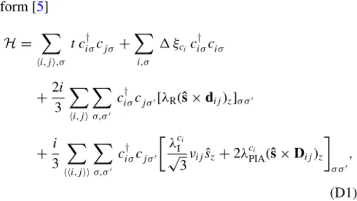
form [5]
H=
i,j,σ
t c†iσcj σ +
i,σ
ξcic†iσciσ
+2i 3
i,j
σ,σ
c†iσcj σ[λR(ˆs×dij)z]σ σ
+i 3
i,j
σ,σ
c†iσcj σ λcIi
√3νijsˆz+2λcPIAi (ˆs×Dij)z
σ σ
,
(D1) whereciσ† =(aiσ† ,b†iσ) andciσ =(aiσ,biσ) denote the creation and annihilation operators for an electron on a lattice sitei that belongs to the sublattice A or B, respectively, and hosts spin σ. The first two terms in Eq. (D1) govern dynamics on the orbital energy scale; the nearest-neighbor hopping (sum over i,j) is parametrized by a hybridization t, and the staggered onsite potential accounts for an effective energy difference experienced by atoms in the sublattices A (ξai =1) and B (ξbi = −1), respectively. The three remaining terms in H [Eq. (D1)] describe spin-orbit coupling (SOC) via the nearest- (sum overi,j) and next-nearest- (sum over i,j) neighbor hoppings. The first of the last three terms is the Rashba SOC parametrized byλR. It arises because the inversion symmetry is broken when graphene is placed on top of WSe2. The last two next-nearest-neighbor terms in Eq. (D1) are the sublattice resolved intrinsicλcIi =λAI (λBI) for ci on sublattice A (B), and the pseudospin inversion asymmetry (PIA) induced term parametrized by λcPIAi =λAPIA(λBPIA) for ci on sublattice A (B), respectively. Both terms appear since the sublattice (pseudospin) symmetry is broken on average.
Here,ˆsis a vector of Pauli matrices acting on the spin space and the sign factor νij =1 (−1) stands for the clockwise (counterclockwise) hopping path from site j to site i. The unit vectors pointing from site j to site i are denoted by dij for the nearest neighbors, and byDij for the next-nearest neighbors.
APPENDIX E: TIGHT-BINDING HAMILTONIAN IN THE BLOCH BASIS
To calculate the energy spectrum, we rewrite the orig- inal tight-binding Hamiltonian H [Eq. (D1)] via the as- sociated Bloch state operators cσ†(q) and cσ(q) defined as follows:
c†σ(q)= 1
√N
m
eiq·Rmc†m,σ, (E1)
cσ(q)= 1
√N
m
e−iq·Rmcm,σ, (E2)
whereRmis the lattice vector of an atomic sitem, andmruns over allN atomic sites (in the given sublattice) forming the macroscopic system. After the transformation,H=
qH(q), the particular Bloch HamiltonianH(q) when expressed in the
ordered Bloch basis,{a↑(q),a↓(q),b↑(q),b↓(q)}, is given as follows:
H(q)=
⎛
⎜⎜
⎜⎝
−λAI fI(q) λAPIAfPIA(q) t forb(q) iλRfR(q) λAPIAfPIA∗ (q) +λAI fI(q) iλRfR∗(−q) t forb(q)
t forb∗ (q) −iλRfR(−q) −+λBI fI(q) −λBPIAfPIA(q)
−iλRfR∗(q) t forb∗ (q) −λBPIAfPIA∗ (q) −−λBI fI(q)
⎞
⎟⎟
⎟⎠. (E3)
The orbital and spin-orbital structural tight-binding functionsforb, fI, fR, fPIAare defined as follows:
forb(q)=1+2ei
√3 2qya
cosqxa, fR(q)=2
3
1+e−i2π3e2i(qx+
√3qy)a+ei2π3e2i(−qx+
√3qy)a
, (E4)
fI(q)= 4 3√
3
cos
√3qya
2 −cosqxa 2
sinqxa
2 , fPIA(q)= 4 3i
cos
√3qya 2 sinqxa
2 +sinqxa−i√
3 cosqxa 2 sin
√3qya 2
,
(E5) wherea=2.46 ˚A, andqx andqy are the Cartesian components of theqvector with respect to the center of the Brillouin zone (). The low-energy physics near the given valleyκK can be effectively described by the HamiltonianH(κK+k) expanded in kto the first order, keeping for each coupling constant only the leading term in thekexpansion. For example, at the K valley we get
HKeff(k)=
⎛
⎜⎜
⎜⎜
⎝
+λAI aλAPIA(−ikx−ky) a√23t(kx−iky) 0 aλAPIA(ikx−ky) −λAI 2iλR a
√3
2 t(kx−iky) a√3
2 t(kx+iky) −2iλR −−λBI aλBPIA(ikx+ky) 0 a√23t(kx+iky) aλBPIA(−ikx+ky) −+λBI
⎞
⎟⎟
⎟⎟
⎠=Horb+HI+HR+HPIA, (E6)
where Horb, HI, HR, andHPIA are explicitly written in the paper [see Eqs. (1)–(4)] with the velocity vF=√23at /. This demonstrates the consistency of the effective Hamil- tonian H in the paper and the TB Hamiltonian described here.
The parameters for the TB Hamiltonian are included in TableI. The calculated electronic band structure for a zigzag nanoribbon of graphene on WSe2, of 4.3 nm width, is shown in Fig.12. Zooms of such a band structure at the region around the Fermi level are in Fig.4(a), for a wider ribbon.
-8 -6 -4 -2 0 2 4 6 8
0 π/a 2π/a
E−EF[eV]
FIG. 12. Calculated band structure for a zigzag graphene nanorib- bon on WSe2 with the width of 4.3 nm. Relevant tight-binding parameters used in the calculation are from TableI.
APPENDIX F: RASHBA ANTICROSSING GAPRAND ITS WAVE VECTORkR
As discussed in the paper, the helical edge states live inside the Rashba anticrossing gap R. Here, we study this gap with our tight-binding model, and provide analytical formulas which demonstrate clearly its origin.
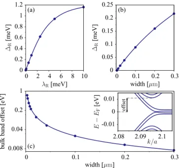
In Fig.13(a), we plotRas a function of the Rashba SOC parameterλR for a narrow nanoribbon of 200 nm. The gap increases linearly withλRfor small, but physically relevant,λR, then it starts to saturate. Also, for theλRparameter of graphene on WSe2, the Rashba anticrossing gap increases linearly with increasing nanoribbon width [see Fig.13(b)], expected to reach the bulk gap of about 0.56 meV at large widths.
We also looked at the offset between the bulk and edge nanoribbon states. The results are shown in Fig. 13(c). As the nanoribbon width increases, the bulk states move closer to the zero-energy level. For a relatively wide nanoribbon of 0.3μm, the Rashba gap R=0.2 meV and the bulk band offset is 7 meV.
Finally, we give analytical estimates of the Rashba anti- crossing energy R and the wave vector kR at which the anticrossing occurs. These are the main characteristics of the inverted band structure. To this end, we analyze the spectrum ofHKeff(k). We considerHorb+HIas the unperturbed Hamiltonian and treatHRas a perturbation. We neglect the PIA HamiltonianHPIAbecause of itskdependence near the center of theκK valley; the effects ofλPIA there are much weaker than that ofλR. The eigenspectrum ofHorb+HIreads as
E±,±(k)= ±λAI −λBI
2 ±
3t2a2|k|2
4 +
−λAI +λBI 2
2
.
(F1)
0 0.2 0.4 0.6 0.8 1 1.2
0 2 4 6 8 10
ΔR[meV]
λR[meV]
(a)
0 0.05 0.1 0.15 0.2 0.25
0 0.1 0.2 0.3
ΔR[meV]
width [μm]
(b)
0.008 0.04 0.2 1
0 0.1 0.2 0.3
bulkbandoffset[eV]
width [μm] (c)
-0.01 0 0.01
2.08 2.09 2.1 E−EF[eV]
k/a
offset
FIG. 13. Calculation of the Rashba anticrossing gapR for a zigzag graphene nanoribbon on WSe2 (a) as a function of Rashba SOC strength for a fixed narrow nanoribbon of 200 nm width, (b) as a function of the nanoribbon width for a fixedλR=0.56 meV. (c) Energy offset of the nanoribbon states with a bulk character (see inset) as a function of nanoribbon width. Model parameters are provided in TableI.
Depending on the relative signs and magnitudes of,λAI and λBI, two bands out of fourE±,±(k) always cross. The momenta where this crossing happens form a circle with radiuskRaround each valley center. In our representative case corresponding to graphene on WSe2the magnitudes of the relevant parameters are ordered as 0< < λBI <−λAI, and in this configuration the bandsE+,+(|k|) andE−,−(|k|) cross at
kR= 2
√3t a
−λAI
λBI −
. (F2)
The perturbationHR removes the degeneracy along the kR circle and opens a gapR. TreatingHRwithin the first-order perturbation theory for degenerate spectra we obtain
R=E−pert,−(kR)−E+pert,+(kR)
=4λR
λBI − λBI −λAI
1+
λBI +2
λBI −
−λAI −1/2
.
(F3) Plugging for the staggered potentialand SOC strengthsλAI, λBI, andλRfrom TableI, we get for graphene on WSe2 kR= 0.2 [10−3/A] and˚ R=0.6 meV. These values are a very good approximation to the computed DFT characteristics of the inverted band structure as seen in Fig.3(d).
[1] W. Han, R. K. Kawakami, M. Gmitra, and J. Fabian, Nat.
Nanotechnol.9,794(2014).
[2] I. ˇZuti´c, J. Fabian, and S. Das Sarma,Rev. Mod. Phys.76,323 (2004).
[3] J. Fabian, A. Matos-Abiague, C. Ertler, P. Stano, and I. ˇZuti´c, Acta Phys. Slovaca57,565(2007).
[4] A. H. Castro Neto and F. Guinea,Phys. Rev. Lett.103,026804 (2009).
[5] M. Gmitra, D. Kochan, and J. Fabian,Phys. Rev. Lett. 110, 246602(2013).
[6] J. Balakrishnan, G. Kok, W. Koon, M. Jaiswal, and A. H. C.
Neto,Nat. Phys.9,284(2013).
[7] A. Avsar, J. Y. Tan, T. Taychatanapat, J. Balakrishnan, G. K.
W. Koon, Y. Yeo, J. Lahiri, A. Carvalho, A. S. Rodin, E. C. T.
OFarrellet al.,Nat. Commun.5,4875(2014).
[8] Z. Qiao, S. A. Yang, W. Feng, W.-K. Tse, J. Ding, Y. Yao, J. Wang, and Q. Niu,Phys. Rev. B82,161414(2010).
[9] C. Weeks, J. Hu, J. Alicea, M. Franz, and R. Wu,Phys. Rev.
X1,021001(2011).
[10] H. Zhang, C. Lazo, S. Bl¨ugel, S. Heinze, and Y. Mokrousov, Phys. Rev. Lett.108,056802(2012).
[11] Z. Qiao, W. Ren, H. Chen, L. Bellaiche, Z. Zhang, A. H.
MacDonald, and Q. Niu,Phys. Rev. Lett.112,116404(2014).
[12] C. L. Kane and E. J. Mele,Phys. Rev. Lett.95,146802(2005).
[13] B. A. Bernevig, T. L. Hughes, and S.-C. Zhang,Science314, 1757(2006).
[14] M. K¨onig, S. Wiedmann, C. Br¨une, A. Roth, H. Buhmann, L.
W. Molenkamp, X.-L. Qi, and S.-C. Zhang,Science318,766 (2007).
[15] H. Zhang, C.-X. Liu, X.-L. Qi, X. Dai, Z. Fang, and S.-C. Zhang, Nat. Phys.5,438(2009).
[16] K. F. Mak, C. Lee, J. Hone, J. Shan, and T. F. Heinz,Phys. Rev.
Lett.105,136805(2010).
[17] A. Korm´anyos, G. Burkard, M. Gmitra, J. Fabian, V. Z´olyomi, N. D. Drummond, and V. Fal’ko,2D Mater.2,022001(2015).
[18] Y.-C. Lin, N. Lu, N. Perea-Lopez, J. Li, Z. Lin, X. Peng, C. H.
Lee, C. Sun, L. Calderin, P. N. Browninget al.,ACS Nano8, 3715(2014).
[19] M.-Y. Lin, C.-E. Chang, C.-H. Wang, C.-F. Su, C. Chen, S.-C.
Lee, and S.-Y. Lin,Appl. Phys. Lett.105,073501(2014).
[20] A. Azizi, S. Eichfeld, G. Geschwind, K. Zhang, B. Jiang, D.
Mukherjee, L. Hossain, A. F. Piasecki, B. Kabius, J. A. Robinson et al.,ACS Nano9,4882(2015).
[21] C.-P. Lu, G. Li, K. Watanabe, T. Taniguchi, and E. Y. Andrei, Phys. Rev. Lett.113,156804(2014).
[22] S. Larentis, J. R. Tolsma, B. Fallahazad, D. C. Dillen, K.
Kim, A. H. MacDonald, and E. Tutuc, Nano Lett. 14, 2039 (2014).
[23] S. Bertolazzi, D. Krasnozhon, and A. Kis,ACS Nano7,3246 (2013).
[24] K. Roy, M. Padmanabhan, S. Goswami, T. P. Sai, G.
Ramalingam, S. Raghavan, and A. Ghosh,Nat. Nanotechnol.
8,826(2013).
[25] W. Zhang, C.-P. Chuu, J.-K. Huang, C.-H. Chen, M.-L. Tsai, Y.-H. Chang, C.-T. Liang, Y.-Z. Chen, Y.-L. Chueh, J.-H. He et al., Sci. Rep.4, 3826 (2014).
[26] N. A. Kumar, M. A. Dar, R. Gul, and J. Baek,Mater. Today18, 286(2015).
[27] M. Gmitra, S. Konschuh, C. Ertler, C. Ambrosch-Draxl, and J. Fabian,Phys. Rev. B80,235431(2009).
[28] P. Giannozzi et al., J. Phys.: Condens. Matter 21, 395502 (2009).
[29] M. M. Ugeda, A. J. Bradley, S.-F. Shi, F. H. da Jornada, Y.
Zhang, D. Y. Qiu, W. Ruan, S.-K. Mo, Z. Hussain, Z.-X. Shen et al.,Nat. Mater.13,1091(2014).
[30] M. Gmitra and J. Fabian,Phys. Rev. B92,155403(2015).
[31] S. Konschuh, M. Gmitra, and J. Fabian,Phys. Rev. B82,245412 (2010).
[32] Z. Wang, D.-K. Ki, H. Chen, H. Berger, A. H. MacDonald, and A. F. Morpurgo,Nat. Commun.6,8339(2015).
[33] J. P. Perdew, K. Burke, and M. Ernzerhof,Phys. Rev. Lett.77, 3865(1996).
[34] S. Grimme,J. Comput. Chem.27,1787(2006).
[35] V. Barone, M. Casarin, D. Forrer, M. Pavone, M. Sambi, and A. Vittadini,J. Comput. Chem.30,934(2009).
[36] L. Bengtsson,Phys. Rev. B59,12301(1999).
[37] J. W. McClure and Y. Yafet, inProceedings of the 5th Conference on Carbon(Pergamon, New York, 1962), Vol. 1, pp. 22–28.
