Sewage Sludge
Location Based Solutions for Thermal Sewage Sludge Utilization and Phosphorus Recovery
– Current Projects at EVN / WTE / S2E –
Thomas Gröbl
1. Sewage sludge management and utilization ...408
1.1. Developments in sludge management and utilization ...409
1.2. Advantages of thermal sewage sludge utilization ...410
1.3. Legal framework ...410
1.3.1. Austria: Federal Waste Management Plan 2017 (BAWP 2017) ...410
1.3.2. Germany: Sewage Sludge Ordinance (AbfKlärV) ...411
1.4. Fuel characteristics of sewage sludge ...412
1.4.1. Calculation of lower heating value – Connection with the water and ash content ...413
1.5. Measures to increase the heating value ...414
1.5.1. Thermal drying of dewatered sewage sludge ...414
1.5.2. Addition of additional fuel...416
1.6. Selection of the plant configuration ...416
2. Current projects at EVN, WTE and S2E ...417
2.1. Thermal sludge utilization plant Dürnrohr ...417
2.1.1. Situation on site – Existing plant...417
2.1.2. Reconstruction to a thermal sewage sludge utilization plant ...419
2.1.3. Framework conditions...419
2.1.4. Plant concept and reconstruction measures ...420
2.2. Thermal sludge utilization plant Halle-Lochau...423
2.2.1. Framework conditions...423
2.2.2. Plant concept ...424
2.3. Sewage sludge mono-incineration plant Tubli ...427
2.3.1. Framework conditions...427
2.3.2. Plant concept ...428
3. References ...431
Sewage Sludge
Sewage sludge is the residue respectively waste product from waste-water treatment and consists of water and a mixture of separated solids. Municipal sewage sludge from municipal waste-water treatment plants usually contains plant nutrients such as nitrogen and phosphorus. In addition, sewage sludge is contaminated with heavy metals from the waste-water and may additionally contain pollutants such as poorly degradable organic substances, microplastics, hormones, endocrine disruptors, pathogenic germs, drug residues, synthetically produced nanomaterials etc.
1. Sewage sludge management and utilization
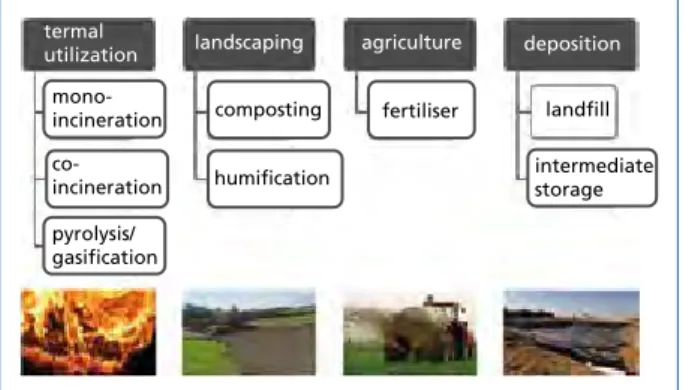
Figure 1 shows the different possibilities of sewage sludge disposal and utilization.
These can essentially be assigned to thermal or material utilization.
termal
utilization landscaping agriculture deposition mono-
incineration co- incineration pyrolysis/
gasification
composting
humification
fertiliser landfill intermediate storage
In 2016, a total of approximately 238,000 tonnes of municipal sewage sludge (calculated as dry substance) was generated in Austria by municipal sewage treatment plants with a capacity of 2,000 PE (population equivalent) or larger [7]. Of which were
• approximately 20 % applied to agricultural land,
• approximately 53 % thermally treated by making use of the waste heat (also decen- tralized) and
• approximately 27 % treated differently (e.g. composting, mechanical-biological treatment, humification).
Municipal sewage sludge is comparatively rich in phosphorus and thus represents a considerable phosphorus potential. Egle and Rechberger [4] indicate that the municipal sewage sludge produced in Austria contains an annual load of about 6,600 tonnes of phosphorus, which corresponds to about 40 % of the annual amount of mineral fertilizer.
In Austria, a closed cycle through exploitation of this potential is currently only given by the application of sewage sludge to agricultural land. Due to the above mentioned pollutants contained in the sludge, however, this is to be considered as critical and is discussed increasingly controversial. A rethink in sewage sludge management can be observed, shifting away from direct agricultural application. As an appropriate and very promising alternative the thermal sewage sludge utilization moves into focus.
Figure 1:
Possibilities of sewage sludge disposal and utilization
Sewage Sludge
1.1. Developments in sludge management and utilization
A number of factors can be cited as drivers in the development or change of disposal respectively recovery routes and strategies. These are essentially based on a fundamental change in disposal practices as well as on the aim of cycle closure through phosphorus recovery to secure food production.
Change in the disposal practice of sewage sludge and elimination of disposal routes
• Increasing demands on the quality of sewage sludge for agricultural use (hygiene standards, heavy metals).
• Direct agricultural application and composting is increasingly considered critical (poorly degradable organic substances, microplastics, hormones, endocrine dis- ruptors, pathogenic germs, drug residues, synthetically produced nanomaterials).
• Substance-related and soil-related limit values as well as limitation of application quantities.
• Restrictions of food manufacturers due to private legal agreements (e.g. AMA qua- lity label).
• Prohibition of direct agricultural application and composting (corresponding tran- sitional periods - legal framework).
• Elimination/restriction of conventional disposal routes.
Creating the conditions for phosphorus recovery from sewage sludge ashes – cycle closure
• Phosphorus is essential for all types of life and therefore is not substitutable at least not in all biological applications.
• The phosphorus reserves (as phosphate) are limited and according to [2] a statistical range of about 300 years can be expected.
• Increasing contamination of raw phosphate with cadmium and uranium.
• 85 to 90 % of the world‘s remaining reserves are spread over Morocco and West Sahara, China, Algeria, Syria and South Africa [2].
• Europe is strongly dependent on phosphorus imports. Thus, phosphorus was clas- sified as a critical raw material by the European Commission in May 2014.
• Reduction of import dependencies on raw material suppliers by recycled phos- phates. The theoretical substitution potential of mineral fertilizers in Austria is approximately 40 % [4].
• The Federal Waste Management Plan 2017 (Austria) supports the recovery and utilization of phosphorus contained in sewage sludge [5, 6, 7].
• The amendment to the sewage sludge ordinance in Germany became effective in October 2017. This provides the obligation to recover phosphorus for wastewater treatment plants with a capacity of 50,000 PE or larger [3].
Sewage Sludge
1.2. Advantages of thermal sewage sludge utilization
The aim of future sewage sludge management is the recovery of phosphorus from the sewage sludge together with simultaneous secured destruction of all pollutants. The thermal sewage sludge treatment – practised in the form of a mono-incineration of sewage sludge with subsequent phosphorus recovery from the generated sewage sludge ash - represents an appropriate and very promising approach for the achievement of this goal. By this recovery and utilization of phosphorus as well as defined and secured pollutant sinks are assured. At the same time, the highest recovery rates are achieved by sewage sludge mono-incineration and subsequent recovery of phosphorus from the ash.
Minimization of pollutants
• Defined and secured pollutant sinks by binding of pollutants and subsequent dum- ping of the corresponding residues under controlled and safe conditions.
• Destruction of organic pollutants, germs, hormones, endocrine disruptors, etc. due to adequate residence time of the flue gases at sufficiently high temperatures.
Minimization of disposal costs
• Quantity and mass reduction.
• Utilization of combustion heat.
Note: Utilization of potential synergy effects is essential for economic efficiency (site selection).
1.3. Legal framework
Clearly, the legal framework conditions constitute a significant driver for the deve- lopments and changes in the sewage sludge management and utilization. As already mentioned, these strongly influence the disposal practice of sewage sludge, both directly – through prohibitions and regulations – and indirectly – by elimination or restriction of individual disposal routes. The corresponding relevant legal framework conditions for Austria and Germany are listed below.
1.3.1. Austria: Federal Waste Management Plan 2017 (BAWP 2017)
The Federal Waste Management Plan 2017 [5, 6, 7] was published at the homepage of the Federal Ministry of Sustainability and Tourism (BMNT) in January 2018 (https://
www.bmnt.gv.at/umwelt/abfall-ressourcen/bundes-abfallwirtschaftsplan.html).
The BAWP 2017 supports the recovery and utilization of phosphorus contained in sewage sludge. Statements on sewage sludge utilization can be found in [5] within the chapter Strategy for future sewage sludge management (page 260 and following) and the basic statements are briefly summarized below.
The objective of future sewage sludge management is the recovery of phosphorus from the sewage sludge under the aspect of extensive destruction of pollutants contained in
Sewage Sludge
sewage sludge respectively the creation of secured pollutant sinks. However, prohibi- tion of direct agricultural application is not included in BAWP 2017 (contrary to the previously published draft).
Mono-incineration of sewage sludge and phosphorus recovery from the incineration ash is to be considered as a promising technology for phosphorus recovery. Co-firing is only permitted with fuels or wastes which either have substantial phosphorus content themselves (e.g. meat-and-bone meal) or which have a low ash content (e.g. natural gas, waste oil) and which do not lead to a relevant increase in pollutant concentrations in the ash.
Alternatively, phosphorus recovery from the waste-water, muddy water or sewage sludge may be applied. Thereby, a phosphorus recovery rate of at least 45 % by mass, based on the inflow of the sewage treatment plant, is to be aimed at.
The aim until 2030 is that 65 to 85 % of the municipal sewage sludge produced in Austria undergoes phosphorus recycling.
Furthermore, it is pointed out that due to the pollutants contained in sewage sludge the agricultural utilization of sewage sludge is not secured for the future.
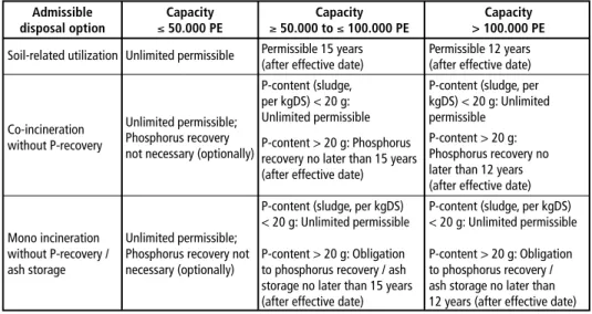
1.3.2. Germany: Sewage Sludge Ordinance (AbfKlärV) The amendment to the sewage sludge ordinance in Germany became effective in October 2017. It aims to further reduce soil-related utilization of sewage sludge in agriculture and increase phosphorus recovery (Table 1). Furthermore, the new version of the Fertilizer Act and the German Fertilizer Ordinance (DüMV) makes agricultural sewage sludge utilization more difficult.
Admissible Capacity Capacity Capacity
disposal option ≤ 50.000 PE ≥ 50.000 to ≤ 100.000 PE > 100.000 PE Soil-related utilization Unlimited permissible Permissible 15 years Permissible 12 years
(after effective date) (after effective date) P-content (sludge, P-content (sludge, per per kgDS) < 20 g: kgDS) < 20 g: Unlimited Unlimited permissible; Unlimited permissible permissible
Co-incineration
Phosphorus recovery P-content > 20 g: Phosphorus P-content > 20 g:
without P-recovery
not necessary (optionally) recovery no later than 15 years Phosphorus recovery no
(after effective date) later than 12 years
(after effective date) P-content (sludge, per kgDS) P-content (sludge, per kgDS)
< 20 g: Unlimited permissible < 20 g: Unlimited permissible Mono incineration Unlimited permissible;
without P-recovery / Phosphorus recovery not P-content > 20 g: Obligation P-content > 20 g: Obligation ash storage necessary (optionally) to phosphorus recovery / ash to phosphorus recovery /
storage no later than 15 years ash storage no later than (after effective date) 12 years (after effective date) Source: Bergs, C.-G.: Phosphor-Strategie des Bundes: Stand der Umsetzung durch die Klärschlammverordnung. Stuttgart, Kongress Phosphor, 26. bis 27.10.2016 (German)
Table 1: Sewage Sludge Ordinance (AbfKlärV)
Sewage Sludge
dewatered sludge
water
ash organic
dry- substance (DS)
organic dry substance (oDS)
Cl S N O H C
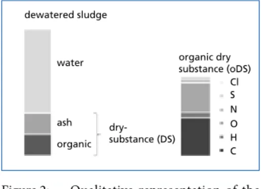
Figure 2: Qualitative representation of the components of dewatered, muni- cipal sewage sludge (left) and ele- mental composition of the organic dry matter (right)
As stated initially, sewage sludge consists of water and a mixture of separated orga- nic and inorganic solids. When dewate- red, municipal sewage sludge usually has a water content of 70 to 80 %, depending on the effectiveness of the dewatering device.
Organics as well as ash content are usually based on the dry substance (DS): 40 to 75
% of the dry matter consists of organics and accordingly 25 to 60 % of ash. Figure 2 qualitatively shows the composition of dewatered, municipal sludge and an elemental composition of the organic dry matter.
It becomes obvious that municipal, dewatered sewage sludge is a fuel with very high water content. In addition, sewage sludge has comparatively high ash content – and consequently a correspondingly low proportion of organics. The thermal fuel properties associated with such fuel composition have significant effects on thermal utilization.
This becomes particularly clear by a comparison with other solid fuels (e.g. household waste, hard coal), as shown in Figure 3.
0 20 40 60 80 100
dewatered sludge
waste coal
water ash/inert organic
share
%
Due to the high water and ash content, municipal, dewatered sewage sludge is a low calorific fuel. This means that the comparatively low energy content contained in the sewage sludge has to be utilized in a best possible manner in order to ensure a thermally self-sufficient utilization process. For description and quantification of the energy content of a fuel, the so called calorific value is used.
Figure 3:
Qualitative fuel comparison of dewatered, municipal sewage sludge with municipal residual waste and hard coal
1.4. Fuel characteristics of sewage sludge
Sewage Sludge
1.4.1. Calculation of lower heating value – Connection with the water and ash content The lower heating value (LHV) constitutes an expression of the chemically bound energy content of a material. It gives the energy released during complete oxidation of a unit of fuel to the fully oxidized gas species CO2, H2O, N2 and/or SO2 at standard conditions and can generally be described according to Eq. (1), given by Pröll [9].
(1) For gas species i, respectively for species with a defined molecular structure in ge- neral, the LHV (molar/volume specific) is derived directly from tabulated standard state molar enthalpies of formation H0f at 298 K (tabulated values are provided e.g. by Barin [1]) according to Eq. (2). Per definition, water contained in the combustion gas is assumed to be gaseous.
(2) The LHV of a multicomponent mixture is then calculated by linear combination of species LHV’s, with the molar species fractions yi.
(3) Because municipal, dewatered sewage sludge, respectively organic substances in gene- ral, are usually not defined on a molecular basis, their lower heating value cannot be determined straight forward from Eq. (1). Instead, the heating value is either defined by the user (measured) or estimated based on the ultimate analysis, whereby e.g. the well-known empiric correlation of Boie (Eq. (4)) is applied (lhv mass specific in kJ/kg).
(4) Here μk denote the mass fractions the elements according to the ultimate analysis. The lower heating value given by Eq. (4) thus refers to the water- and ash-free state of the organic material, i.e. the organic dry substance (oDS) of the dewatered sewage sludge.
With water and ash defined as mass fractions of the total mass, the lower heating value of the original matter can be calculated according to Eq. (5), given by Pröll and Hofbauer [9].
(5) With ash and organic content defined as fractions of the dry substance, Eq. (5) can be formulated as follows.
(6) In case of dewatered sewage sludge, specification of the heating value often is referred to the dry substance (DS). Eq. (7) below provides the relation between the heating value of the dry substance and that of the organic dry substance.
(7) According to the above given equations, it becomes clear that the lower heating value of dewatered sewage sludge strongly depends on the water and ash content.
Cζ1Hζ2 ζ2
Oζ3Nζ4Sζ5+(ζ1+ 4 –ζ23+ζ5)O2 ζ22 H2O+ζ24N2+ζ5SO2
LHVi=H0,298,iƒ –ζ1H0,298,COƒ 2–ζ22H0,298,Hƒ 2O(g)–ζ5H0,298,SOƒ 2
LHV =∑Ni=1 yiLHVi
lhvwaƒ =34,835μC + 93,870μH– 10,800μO+ 6,280μN+ 10,465μS
lhv=(1 – wash – wH2O)lhvwaƒ– wH2O 2462.6
lhv=(1 – wH2O)oDS lhvwaƒ– wH2O 2462.6
lhvDS= oDS lhvwaƒ
Sewage Sludge
1.5. Measures to increase the heating value
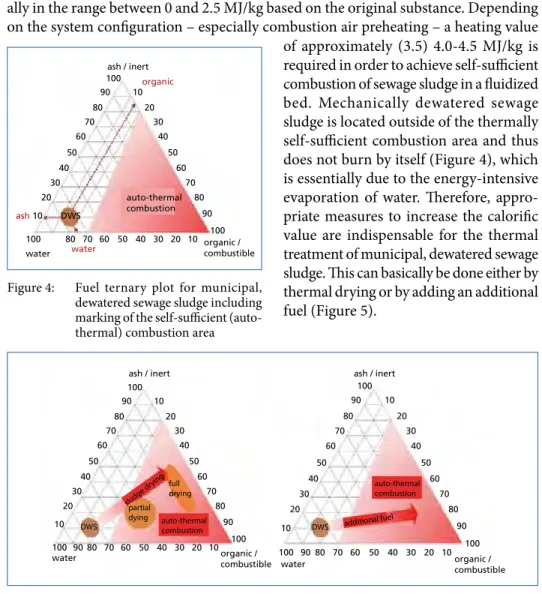
Calorific values of typical municipal, mechanically dewatered sewage sludge are usu- ally in the range between 0 and 2.5 MJ/kg based on the original substance. Depending on the system configuration – especially combustion air preheating – a heating value
100 100
100
90 90
80
80 80
70
70 70
60
60 60
50 50 50
40 40 40
30 30
30
20 20
20
10 10
10
organic / combustible water
ash / inert
DWS
organic
ash
water
auto-thermal combustion
of approximately (3.5) 4.0-4.5 MJ/kg is required in order to achieve self-sufficient combustion of sewage sludge in a fluidized bed. Mechanically dewatered sewage sludge is located outside of the thermally self-sufficient combustion area and thus does not burn by itself (Figure 4), which is essentially due to the energy-intensive evaporation of water. Therefore, appro- priate measures to increase the calorific value are indispensable for the thermal treatment of municipal, dewatered sewage sludge. This can basically be done either by thermal drying or by adding an additional fuel (Figure 5).
Figure 4: Fuel ternary plot for municipal, dewatered sewage sludge including marking of the self-sufficient (auto- thermal) combustion area
Figure 5: Measures to increase the heating value of dewaterd sewage sludge: Thermal drying (left) and additional fuel (right)
1.5.1. Thermal drying of dewatered sewage sludge
In the case of thermal drying, a general distinction is made between partial drying and full drying. Approximate ranges of corresponding dry matter and lower heating values are given below.
• Partial drying: DS 40-85 %, LHV 4-7 MJ/kg.
• Full drying: DS > 85 %, LHV 10-12 MJ/kg.
100 100
100
90 90
90
80
80 80
70
70 70
60
60 60
50 50 50
40 40 40
30 30
30
20 20
20
10 10
10
organic / combustible water
ash / inert
100 100
100
90 90
90
80
80 80
70
70 70
60
60 60
50
50 50
40 40
40
30 30
30
20 20
20
10 10
10
organic / combustible water
ash / inert
sludge dr ying
auto-thermal combustion
auto-thermal combustion additional fuel partial
dying DWS DWS
full drying
Sewage Sludge
In case of partial drying, the entire stream of the dewatered sewage sludge passes the drying unit and is dried to such an extent that self-contained combustion in the fluidized bed is ensured. Depending on the content and quality of the organics, this usually is achieved between 40 and 45 % dry substance. When treating well-digested sewage sludge with high ash content, the required degree of drying may be well above.
It should be noted in this regard that during the drying process in the range of 40 to 60 % dry matter, the sewage sludge passes through a sticky viscous phase, the so called adhesion phase. There a strong sticking tendency of the partially dried sewage sludge is to be expected and the sewage sludge tends to caking and strong clumping. The exact range in which this adhesive phase occurs is very difficult respectively hardly predicta- ble and strongly dependent on the sewage sludge itself. According to the sludge, there may be no or considerable tendency for the partially dried sludge to accumulate at a certain DS content.
It must be ensured in any case that partial drying is always operated below this ad- hesive phase in order to avoid sticking and clogging in the dryer and in downstream conveyor units or plant components. In addition, the conveying path of the partially dried sewage sludge should be kept as short as possible.
In case of full drying, the mechanically dewatered sewage sludge is dried almost completely to a dry matter content of 85 % or larger (typically 90 %). Thereby, usually only a partial stream of dewatered sewage sludge passes the drying unit. The required degree of dry substance to ensure self-sufficient combustion in the fluidized bed is then achieved by subsequent back-mixing of the fully dried with the remaining dewatered sewage sludge before feeding to the fluidized bed.
Here, the content of dry substance at the outlet of the drying unit is permanent sig- nificantly above the range of the adhesive phase. Depending on the type of dryer, it is either possible to pass through the adhesive phase in the dryer (e.g. belt dryer) or some of the dried material is fed back and mixed with the dewatered sewage sludge supplied, so that the content of dry substance is always kept above the adhesive phase (e.g. disc dryer).
During subsequent back-mixing of fully dried with dewatered sewage sludge occur- rence of the adhesive phase is significantly weaker or hardly pronounced. This effect provides clear advantages when treating sewage sludge with less organic and / or lower calorific value of the organics.
Moreover, by buffering the fully dried sewage sludge, a decoupling between drying and firing can be achieved. This allows greater flexibility in the operation of the sewage sludge incineration plant.
It should be noted here that due to its properties and ingredients dried sewage sludge has to be processed and stored carefully. Due to possible occurrence of exothermic reactions, because of microbiological activity, in combination with the relatively low thermal conductivity of dried sewage sludge, heating up to spontaneous combustion of dried sewage sludge may occur during storage. However, this can be counteracted by
Sewage Sludge
appropriate measures. According to Heindl [8], the following measures can be stated for a safe storage of dried sewage sludge (amongst others): Temperature in dry sludge silos below 40 °C (if necessary ensured by cooling of the feeding system), minimization of dust content, avoidance of large storage volumes in silos (larger than 100 m³), avoi- dance of rehydration and reduction of moisture accumulations, control by temperature measurement and optional CO measurement.
Thermal drying generally allows a mono-incineration of sewage sludge and thus a pure sewage sludge ash is produced which can be used for later phosphorus recovery.
If the heat released during combustion suffices to supply the drying process as well as additional internal heat consumers, a thermally self-sufficient operation is given.
1.5.2. Addition of additional fuel
An alternative option for increasing the calorific value of the mechanically dewatered sewage sludge constitutes the admixing of a (high-calorific) additional fuel. In this case, the drying is shifted directly into the fluidized bed and the required energy for the eva- poration of water is provided by the additional fuel. Direct drying in the fluidized bed is more energy efficient compared to an upstream thermal drying unit. Furthermore, the usable heat output of such a process configuration is significantly higher.
With regard to phosphorus recovery from sewage sludge ash, co-firing is only practical with fuels or wastes which either themselves have a substantial phosphorus content or which have a low ash content and which do not lead to a relevant increase in pollutant concentrations in the ash.
However, admixing of additional fuel and direct drying in the fluidized bed can provide an economical plant configuration, in particular for sewage sludge that is not subject to phosphorus recovery obligations.
1.6. Selection of the plant configuration
The question concerning an optimal plant and process configuration is subject to a large number of influencing factors and boundary conditions and can by no means be answered generally. Below, an overview of general conditions is given that significantly influence the system configuration (and partly each other).
Local, site-specific framework conditions
• Customer requests and specifications
• Potential synergies from exisiting inf- rastructure and personell
• Internal / external sludge
• Location based restricitions (building site, building height, etc.)
Technical framework conditions
• Plant size / sludge capacity
• Sludge quality and impurities
• Drying concept
• Possibility for discharge or treatment of exhaust vapours
• Flue gas treatment
Sewage Sludge
2. Current projects at EVN, WTE and S2E
Determination of the system configuration, taking into account the general conditions, is shown and clarified below on the basis of three very different projects, currently carried out at EVN AG (EVN), WTE Wassertechnik GmbH (WTE) and sludge2energy GmbH (S2E).
2.1. Thermal sludge utilization plant Dürnrohr
2.1.1. Situation on site – Existing plant On the power plant site of EVN AG, directly next to the coal-fired power plant, in 2007 a pyrolysis demonstration plant was built and operated in order to investigate a possible energetic use of biogenic waste from agricultural residues (mainly straw). Located in the immediate vicinity of the coal block, there is the thermal waste treatment plant Dürnrohr of EVN and together they form an energy network (heat node) via a steam rail (Figure 6).The existing pilot plant (Figure 7) essentially comprises the following parts:
• building / delivery and storage bunker with crane system,
• rotary kiln for pyrolysis,
• fluidized bed furnace for combustion of generated pyrolysis products (pyrolysis char and pyrolysis gas),
• a subsequent spray cooler for cooling the hot flue gas and
• a flue gas treatment system consisting of a spray absorber and a bag filter.
The demonstration plant is designed for a thermal fuel capacity of approximately 3.5 to 5.0 MW. In 2010, in addition to biomass, the use of non-hazardous waste (including sewage sludge) was approved. The pilot plant was operated as an independent plant without connection to the existing power plants – except media supply such as natural gas, steam, compressed air and water. The plant was operated in experimental cam- paigns, alternately as a pyrolysis plant or as a fluidized bed combustion plant, without energetic utilization.
Economic framework conditions
• Sludge disposal costs
• Residue disposal costs
• Waste heat utilization / electricity ge- neration
• Investment costs
• Operating costs
Legal framework conditions
• Emission limit values
• Traffic
• Environment
• Occupational safety and fire protec- tion
• Technical guidlines and standards
Sewage Sludge
In case of pyrolysis operation, the fuels used are gasified in the indirectly heated rotary kiln. The pyrolysis gas generated during the pyrolysis is then fed to the post-combustion chamber of the fluidized bed furnace and burned and the resulting pyrolysis char is stored in a bunker. The hot gas required for the rotary kiln heating is diverted from the combustion chamber.
In case of fluidized bed operation, the produced pyrolysis coke, biomass and non- hazardous waste are incinerated (at standstill of the rotary kiln). The fluidized bed furnace is designed as an adiabatic, stationary fluidized bed incinerator with staged combustion air supply and SNCR system for reduction of NOX.
Independently of the operating mode, the hot flue gases are cooled in a spray cooler and fed to the flue gas cleaning, by which – due to the previous concept as a demonstration plant – the energy contained in the feedstock remains unused.
As a follow-up project, it was planned to build a larger-capacity pilot plant which was connected to the coal-fired power plant in order to use the generated pyrolysis products in the coal-fired power station and thereby save fossil coal. However, for the reasons stated below, this project was not implemented and the pilot plant was shut down.
coal-fired power plant Dürnrohr (PPD)
demonstration plant / sludge treatment plant waste treatment plant
Dürnrohr (WTPD)
steam line WTPD to PPD (ca. 300 m)
Figure 6:
Situation on site-Energy net- work Dürnrohr
Figure 7: Demonstration plant and 3D model
• Significant increase in the price of straw.
• CO2-certificates did not develop as expected.
• Operation of coal block developed from base load coverage to peak load coverage, with appropriate plant operation mode and significantly reduced operation times.
• Non-continuous operation is not optimal for the pyrolysis system.
Sewage Sludge
2.1.2. Reconstruction to a thermal sewage sludge utilization plant Already in 2011 considerations were made about a reconstruction of the demonstration plant to a sewage sludge utilization plant with subsequent commercial operation, but these were not considered any further for predominantly economic reasons. Against the background of ongoing developments on the sewage sludge market these considera- tions were resumed in 2014. A comprehensive feasibility study, including technical and economic evaluation, was carried out. Based on this, the project shall be implemented.
The planned plant is to be optimized in terms of energy efficiency and operation.
Additionally both, capacity and type of used waste is to be extended. Treatment of the input materials will not be discontinuously as before, but continuously and the heat energy generated is to be used via steam generation and incorporated into the existing energy network.
2.1.3. Framework conditions In this case, the plant concept is significantly influenced by the existing demonstration plant and infrastructure, the energy network, the local conditions on site as well as the existing permits.
Technical conditions
In the planned concept reconstruction or extension to a sewage sludge incineration plant, as many plant components as possible should be reused, amongst others
• building / delivery and storage bunker with crane system,
• fluidized bed furnace and
• bag filter.
Local conditions
• Existing energy network:
- Coal-fired power plant: 350 MWel
- Waste treatment plant: 3 furnace lines, 210 MWth - Process heat for bioethanol production: 430 GWh/a; 500,000 t/a - District heating St. Pölten
- District heating Zwentendorf
• The thermal sludge utilization plant is to be incorporated into the existing energy network.
• There is no sufficiently large sewage treatment plant for the initiation of any resulting vapours respectively waste-water from sludge drying. Therefore, a special focus is to be laid on the safe disposal or recovery of the vapours respectively to avoid these.
Sewage Sludge
2.1.4. Plant concept and reconstruction measures
In the course of a comprehensive feasibility study, several plant variants were considered both technically and economically. A summary is given in Table 2.
Variant 1 Variant 2 Variant 3
Mono-incineration Mono-incineration Co-incineration Utilization of the rotary kiln Direct sludge drying in the fluidized for sludge drying. Installation of a thermal sludge dryer.
bed by additional fuel.
No steam boiler. Installation of a steam boiler. Installation of a steam boiler.
No revenue from steam/heat. Little revenue from steam/heat. Highest revenue from steam/heat.
Limitation of sewage sludge quantity Issue vapours: No waste-water Pollution/dilution of sewage sludge due to evaporation capacity
treatment plant for initiation. ash by additional fuel.
of rotary kiln.
Capacity dewatered sewage sludge Additional investment costs for
max. 12,000 t/a. drying unit. – g Uneconomically g Uneconomically g Economically Table 2: Comparison of analysed and evaluated variants
Under the given framework conditions for the Dürnrohr site, the variant with the addition of high calorific additional fuel has proven to be the economic and technical optimal plant configuration. The following points can be given as main reasons for this:
• Elimination of the issue regarding dryer vapours:
(i) There is no sufficiently large waste-water treatment plant for the discharge of vapour wastewater.
(ii) A treatment of the vapour waste-water is quite complex and costly.
(iii) A complete utilization of vaporous vapours (without vapour condensation) in the fluidized bed firing is not possible both quantitatively and energetically.
• Lower investment costs due to the direct drying in the fluidized bed instead of installation of an additional drying plant.
• Higher steam generation due to the energy content of the additional fuel and thus higher revenue from steam/heat.
• Familiarity with the waste market (purchase of additional fuel) due to the operation of the neighbouring thermal waste treatment plant.
It is thus planned to reconstruct the demonstration plant to a fluidized bed combus- tion plant for the incineration of sewage sludge and non-hazardous waste (additional fuel). The fuel heat output remains unchanged from the existing system. So far sewage sludge, biomass and the resulting products as well as non-hazardous waste were used as a feedstock. Now sewage sludge and quality-assured, non-hazardous waste is to be incinerated. The indirectly fired rotary kiln for pyrolysis of the feedstock will be shut down and the plant will in future only be operated in fluidized bed operation. Due to the omission of the pyrolysis operation, accordingly, no pyrolysis coke and pyrolysis gas are produced. In the planned, optimized system, the fluidized bed furnace will remain and a waste heat boiler for heat utilization is to be installed. The generated steam is to be fed into the existing steam network at the power plant site.
Sewage Sludge
Due to the addition of (high calorific) additional fuels, phosphorus recovery from sewage sludge ash is only possible to a limited extent (when using low-ash, phosphorus- rich auxiliary fuels), as described in chapter 1.5.2. It is planned here to use sewage sludge, which are not subject to any obligation for phosphorus recovery due to their composition and/or the capacity of the corresponding waste-water treatment plant.
Fuel logistics
• Delivery of the fuels and removal of the residues via the existing weighing device on the site of the power plant Dürnrohr.
• Separated delivery and storage area for sewage sludge and additional fuel.
• Sludge delivery bunker with a grid for capturing coarse impurities. Charging the sewage sludge storage bunker by means of the existing crane system.
• Fuel feeding of sewage sludge and additional fuel is conducted by the existing crane system.
• Mixing of fuels prior to feeding into the fluidized bed furnace in order to ensure a good energy input of the additional fuel into the fluidized bed.
Firing and energy recovery
• Direct drying in the fluidized bed by addition of the high calorific additional fuel.
• Adiabatic designed, stationary fluidized bed furnace with staged combustion air supply and SNCR system for reduction of NOX.
• A waste heat boiler for generation of saturated steam is installed on top of the flu- idized bed furnace. It is designed as a 2-pass water tube boiler, operated in natural circulation.
Flue gas purification
• The flue gas cleaning system is designed as a dry system.
• Dry sorption based on separate injection of sodium bicarbonate and activated car- bon.
• Bag filter with particle recirculation to improve the separation capacity and reduce the consumption of operating supplies.
Incorporation into the existing energy network
• Live steam from the sewage sludge incineration plant is fed into the low-pressure steam collector of the energy network.
• Condensate – and partly steam for combustion air preheating – is supplied by the energy network.
Reconstruction measures
• For the continuous delivery of fuels, the delivery area needs to be adapted – spatial separation of the areas for sewage sludge and additional fuel.
Sewage Sludge
• Optimization of sewage sludge delivery via a separate sewage sludge delivery bun- ker.
• Optimization of combustion in the existing fluidized bed furnace through adapta- tion of air preheating, nozzle bottom and bed material discharge.
• Shot down of the existing rotary kiln for pyrolysis.
• The existing spray cooler of the demonstration plant is replaced by a saturated steam waste heat boiler with downstream ECO. The steam generated is fed into the low- pressure steam header of the existing energy network.
Figure 8:
Reconstruction measures ther- mal sludge utilization plant Dürnrohr
Parameter Unit Value
Plant availability h/a 7,500 - 8,000
Number of combustion lines - 1
Incinerator - Stationary fluidized bed
Energy utilization - Saturated steam boiler Maximum fuel thermal
capacity total t/a 32,000
Capacity dewatered sludge
(20 – 25 %TS) t/a 20,000
Capacity additional fuel t/a 6,000 – 12,000 Fuel thermal power incineration MW 5 Live steam parameters bar(a) / °C 20 / 212 Live steam generation t/h 7.4 (4.4 – 7.4)
Flue gas Nm³/h,wet 15,000
Steam production MWh/a 40,000
Consumption external steam MWh/a 5,400
Consumption condensate MWh/a 2,700
Table 3:
Basic technical data of the ther- mal sludge utilization plant Dürnrohr
Sewage Sludge
• Optimization of the flue gas cleaning system by integration of a second identical bag filter – instead of the spray absorber – in order to achieve a reduction of the filter surface load during continuous operation.
• Due to the omission of the spray absorber, sodium bicarbonate is used as sorbent instead of hydrated lime.
2.2. Thermal sludge utilization plant Halle-Lochau
In Halle-Lochau, the erection and operation of a sewage sludge mono-incineration plant including electricity generation is planned. Design and erection is done by slud- ge2energy GmbH (S2E), a joint venture of WTE Wassertechnik GmbH – a subsidiary of EVN AG – and Huber SE. WTE operating company (WTEB) is to be responsible for future operation of the thermal sludge utilization plant. Scheduled start of continuous, commercial operation is in July 2020.
2.2.1. Framework conditions Site, local and technical conditions The site is located at the Kreislauf- und Ressourcenwirtschaftspark Halle-Lochau, an industry-focused industrial and commercial area. The available land has an area of approximately 10,000 m², the area required by the thermal sewage sludge utilization plant including required traffic and storage areas is approximately 6,000 m².
There is no sewage treatment plant on site. Thus, the sewage sludge treated is entirely external sludge delivered by road. Furthermore, a return and initiation of vapours from the drying process into a sewage treatment plant is not possible. Consequently, a special focus is to be put on the secure disposal or recovery of the resulting sewage sludge drying vapours.
Legal conditions The sewage sludge utilization plant at Halle-Lochau is to be approved in accordance with §4 of the Federal Immission Control Act (Bundesimmissionsschutzgesetzes BIm- SchG). The submission of the plant is made in the simplified procedure according to
§19 BImSchG. This results in the following capacity limits, which have to be considered for design and optimization of the plant concept:
• Capacity of the drying unit less than 50 t/d and
• Capacity of the fluidized bed incinerator less than 3 t/h.
With regard to the exhaust gas emissions of the incineration plant the requirements of the 17th BImSchV apply.
A permit according to § 9 of the BImSchG is already available since May 15, 2018;
the submission documents for the building permit are currently under preparation.
Submission of the documents is scheduled for September 2018.
Sewage Sludge
2.2.2. Plant concept
When selecting and defining the plant concept, special emphasis was put on high flexi- bility and plant availability. It is delivered both dewatered and externally dried sewage sludge. For economic reasons, the installation should be designed in such a way as to maximize the capacity limits imposed by the simplified procedure, in particular with regard to the use of dewatered sewage sludge. An analysis of the possible use of sewage sludge (dewatered and dried) has been carried out. Based on this, a correspondingly optimal mode of operation was determined. Due to the high rating of electrical energy at the given location, electricity generation is also to be implemented.
Sludge logistics
Dewatered sewage sludge is discharged into a sewage sludge bunker. The sludge hand- ling in the bunker and feeding is conducted by a crane. Delivery of the externally dried sewage sludge takes place in special containers with a walking floor and discharge device, by which also the storage of the dried sludge is realized.
Sludge drying and exhaust vapour treatment
The design of the drying concept as a full drying process allows a significantly better utilization of limitation of the dryer capacity that comes with the simplified approval procedure. As described in chapter 1.5.1, in case of complete drying only a partial stream of the dewatered sewage sludge passes the drying unit, whilst the remaining stream of dewatered sludge is bypassed and subsequent back mixed with the fully dried sludge in order to achieve the required dry matter content for self-sufficient combustion in the fluidized bed.
Since a return and initiation of vapours from the drying process into a sewage treatment plant is not possible at this location, the following variants were analysed and compared both technically and economically:
• Condensation of the vapours and subsequent treatment in order to securely meet the locally specified discharge conditions in the sewer system, or
• Realization of a sewage-free drying system.
A low-temperature belt drying system is to be used, that allows a sewage-free operation of the subsequent vapour treatment. The exhaust air (vapours) from the sludge dryer is subjected to a 2-stage wet scrubber (acidic and alkaline). The acid scrubber product is an ammonium sulphate solution (ASL) which can be distributed as a fertilizer. The residue accumulating in the alkaline scrubber stage can be supplied to the combustion process due to its small amount.
A direct utilization of the untreated exhaust air from the sludge dryer in the incinera- tor is not possible in terms of quantity. In addition, this would lead to a significantly increased water content in the flue gas and thus affect the general concept of flue gas purification. Above a certain water content (about 50 vol%) the use of a wet flue gas cleaning is strongly recommended due to the corresponding high dew point. This in turn results in operational waste-water flow, which requires treatment again.
Sewage Sludge
The dried sewage sludge can be conveyed either directly into a small storage tank prior to incineration or into a storage container via appropriate conveyors.
Firing and energy recovery A stationary fluidized bed furnace with staged combustion air supply and SNCR system for reduction of NOX is to be used. Subsequent to the fluidized bed furnace a waste heat boiler for generation of saturated steam is installed.
Upstream of the fluidized bed furnace a sewage sludge mixer is situated. There dewa- tered sewage sludge from the sewage sludge bunker and dried sludge from the small storage tank are mixed in a metered way.
Energy utilization The energetic utilization of the steam produced in the boiler system is realized via a steam turbine and a generator. The steam turbine for energy utilisation is designed as a back-pressure steam turbine which provides both, highest flexibility towards fluctu- ations in sludge quality as well as appropriate efficiency of electricity generation. The exhaust steam of the turbine (low-pressure steam) is fed to a low pressure steam collector and is used to cover the in-house heat requirements (mostly drying, air pre-heating etc.). Excess steam is condensed in an air condenser and the heat is dissipated to the environment. The exhaust steam parameters of the turbine – and thus the operating pressure of the low-pressure steam collector – were optimised for the supply of the in-house steam loads. The implementation of the low-temperature belt drying system allows a further reduction of the exhaust steam pressure and thus a higher electrical power output.
Flue gas purification The flue gas cleaning system is designed as a dry flue gas cleaning, comprising of
• a bag filter for pre-separation,
• a dosing system for the injection of additives – separate addition of activated coke and sodium bicarbonate – in the flue gas stream (reactor) for dry sorption, and
• a downstream sorption bag filter with particle recirculation to improve the separa- tion capacity and reduce the consumption of operating supplies.
This enables sewage-free flue gas cleaning together with secured compliance of required emission limits. The flue gas cleaning system is designed in such a way that the sewage sludge ash is already almost completely separated from the flue gas by pre-separation before the sorption agent is added, and thus can be used for later phosphorus recovery.
Residues Residues from the thermal sludge utilization plant are divided into sewage sludge ash (bed ash, boiler ash and ash from the pre-separation) and residues from sorption bag filter (fly ash and reaction products from flue gas cleaning). These are discharged from
Sewage Sludge
the plant separated from each other by suitable conveyor systems. Sewage sludge ash is stored in a silo and transported accordingly with silo vehicles. The fabric filter residues are filled in BigBags.
The low-pollutant sewage sludge ash (about 4,000 t/a) represents a significant phospho- rus potential and thus constitutes a valuable source for the production of phosphorus fertilizers. The residues from the sorption filter on the other hand (about 200 t/a) are loaded with sorbents and heavy metals. These are not available for later phosphorus
Figure 9:
Plant design Halle-Lochau
Parameter Unit Value
Plant availability h/a 8,000
Number of combustion lines - 1
Incinerator - Stationary fluidized bed
Energy utilization - Saturated steam boiler
Turbine type - Backpressure steam
turbine Maximum capacity dewatered
sludge (25 %DS) t/a ca. 33,300
Maximum capacity dried sludge
(90 %DS) t/a ca. 2,750
Fuel thermal power
of incineration MW 3,4
Live steam parameters bar(a) / °C 40 / 250
Live steam generation t/h 4.6
Flue gas Nm³/h,wet 10,000
Sewage sludge ash t/a 4,350
Residues from sorption bag filter t/a 230
Table 4:
Basic technical data of the ther- mal sludge utilization plant Halle-Lochau for maximum plant capacity
Sewage Sludge
recovery and must be disposed of due to their pollutant load. As a potential recycling path for the phosphorus-rich sewage sludge ash, e.g. the SERAPLANT process at the Haldensleben location can be stated. The two-stage process principle is based on the residue-free decomposition of the phosphates contained in the ashes by addition of a mineral acid with subsequent spray granulation of the technology partner Glatt Ingenieurtechnik GmbH. In addition to the production of fertilizers with up to 46 % available phosphate content, the process is characterized by the possibility of producing marketable complex fertilizers.
2.3. Sewage sludge mono-incineration plant Tubli
In Tubli (Bahrain) the existing major sewage treatment facility on the Bahraini Island, the Tubli Sewage Treatment Plant (Tubli STP), is to be expanded. As a part of the expansion a sewage sludge mono-incineration plant for the thermal utilization of the amount of sludge produced is to be erected. As a whole, the scope of project for the contractor is to design, procure, construct and operate for ten years after completion all facilities for Tubli STP and peripherally associated units. WTE Wassertechnik GmbH was able to provide the best offer, both technically and commercially. The scheduled start of continuous operation of the plant is in September 2021.
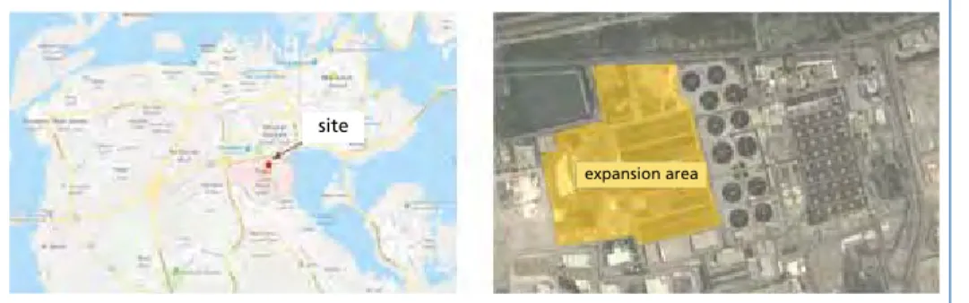
2.3.1. Framework conditions Site information Tubli STP is located at the western side of Tubli Bay between the capital Manama and Isa Town, in an urbanized area. The size of the plant (within the fence) is about 260,000 square meters, its length in E-W direction is about 700 meters, the width (N-S) is about 450 meters. The western part of the area is not used today, so that about 90,000 square meters are available for expansion (Figure 10).
site
expansion area
Figure 10: Tubli STP site and expansion area
The waste-water capacity of the existing Tubli STP is about 200,000 m³ per day and shall be expanded to nominal total treatment plant capacity of 400,000 m³ per day.
Sewage Sludge
Technical and legal conditions
The sludge produced during treatment of the waste-water has to be treated by the thermal sludge treatment plant. This results in following capacity requirement:
Total treatment capacity of 118 tonnes per day as dry substance. With a plant availa- bility of 8,000 operating hours per year, this gives an annual total treatment capacity of 39,330 tonnes as a dry substance.
Emission limits according to EU directive 2010/75/EC apply to the exhaust gas of the incineration plant.
2.3.2. Plant concept Construction of two lines
In order to ensure the reliable disposal of the sewage sludge produced, two lines for drying, incineration, waste heat utilisation, and flue gas purification are realised. These can be operated completely independently of each other, which ensures a high plant availability.
Sludge drying and exhaust vapour treatment
For thermal sludge drying two indirect contact dryers are installed, which are desig- ned as disc dryers for partial sludge drying. This type of dryer was chosen due to the amount of sludge and the comparatively low space demand. The sludge dryers are fed from sludge storage silos and the partial dried sludge is directly feed to the incinerator.
Exhaust vapours produced during drying process, are extracted from the dryers and fed into a three-stage exhaust vapour condensation unit with heat recovery. In the first stage of condensation, in the preheater, the vapours come in direct-contact with a raw/
thin sludge which absorbs the latent heat of evaporation and the process vapour partly returns to liquid state (process condensate). In the second stage preheater, the vapours come in direct-contact with the centrate which absorbs the remaining latent heat of evaporation and the process vapour returns to liquid state. The third stage constitutes an emergency stage, cooled by service water, which is usually not in operation.
The process vapours that cannot be condensed, called non-condensables, are with- drawn from the second (respectively third) stage condenser with a fan and directed to the incineration. The resulting process condensate is directly introduced into the respective heat absorbing medium flow of the sewage treatment plant (i.e. thin sludge respectively centrate).
Firing and energy recovery
The incinerator is designed as a stationary fluidised bed incinerator in such a way that the partially dried sludge can be incinerated without additional fuels during continuous operation. Additional fuel will only be used for the start-up and shut down of the incineration plant and for disturbances and compensation of fluctuations. A suitable
Sewage Sludge
structural design of the incineration chamber and the incineration air supply ensure as early as in the incineration chamber that the formation of nitric oxides (NOX) in the flue gas is minimised. This ensures reliable compliance with the required emission value without additional injection of ammonia water (SNCR process). In addition, the possibility of a later retrofitting with ammonia water injection in the incineration chamber (SNCR process) is included from a technical point of view and the structural design of the incineration will be realised accordingly.
For the energetic use of the heat released during incineration, a steam generator for production of superheated steam is installed downstream of the incineration system.
400 °C and 41 bar(a) are used as steam parameters. Based on our experience and the experience of many operators, these values represent the most favourable and most efficient operating parameters as far as efficient energy production and plant availability are concerned.
Energy utilization The steam turbine for energy utilization is realised as a back-pressure steam turbine which provides both, highest flexibility towards fluctuations in sludge quality as well as high efficiency of electricity generation. The exhaust steam of the turbine (low-pressure steam) is used to cover the in-house heat requirements (drying, air pre-heating, etc.). The exhaust steam parameters were optimised for the supply of the in-house steam loads.
Figure 11:
Plant layout sludge utilization plant Tubli
Sewage Sludge
Flue gas purification
The flue gas cleaning system is designed as a dry system. It comprises of a pre-separation unit with a bag filter, a reactor for conditioned dry sorption based on the injection of hydrated lime and activated carbon and a downstream sorption bag filter with particle recirculation to improve the separation capacity and reduce the consumption of opera- ting supplies. In that way, compliance with the requested emission limits according to 2010/75/EC and the corresponding Bahrain specifications is ensured at comparatively low investment and operating costs. The system is designed in such a way that the sewage sludge ash is separated from the flue gas almost completely by pre-separation before addition of the sorption agent, and thus can be used for later phosphorus reco- very. Nevertheless, phosphorus recovery from the produced sewage sludge ash is not an issue for the time being.
Residues
Residues from the thermal sludge utilization plant are divided into sewage sludge ash (bed ash, boiler ash and ash from the pre-separation) and residues from sorption bag filter (fly ash and reaction products from flue gas cleaning). These are discharged from the plant separately from each other by suitable conveyor systems and stored in silos.
Parameter Unit Value
Plant availability h/a 8,000
Number of combustion lines - 2
Incinerator - Stationary fluidized bed
Energy utilization - Superheated steam
boiler
Turbine type - Backpressure steam
turbine Total capacity dewatered sludge
(24 %DS) as a dry substance tDS/a 39,330 Fuel thermal power
per combustion line MW 7,5
Live steam parameters bar(a) / °C 41 / 400 Live steam generation
per combustion line t/h 9.1
Live steam generation total t/h 18.2
Flue gas per combustion line Nm³/h,wet 19,000
Sewage sludge ash total t/a 12,950
Residues from sorption
bag filter total t/a 1,100
Table 5:
Basic technical data of the ther- mal sludge utilization plant Tubli Nomenclature
DWS Dewatered sludge waf water- and ash-free
Sewage Sludge
Symbol Unit Description
DS kgDS kg-1 Mass fraction of dry substance per unit fuel LHV J mol-1 Lower heating value (volume specific) lhv J kg-1 Lower heating value (mass specific)
oDS kgoDS kgDS-1 Mass fraction of organic dry substance per unit dry fuel y moli mol-1 Molar fraction of species i
μk kgk kg-1 Mass fraction of element k
ζk - Molar stoichiometric coefficient of element k
3. References
[1] Barin, I.: Thermochemical Data of Pure Substances, volume 1&2. VCH, 3rd edition, 1995.
[2] Bayerisches Landesamt für Umwelt (LfU): Rückholbarkeit von Phosphor aus kommunalen Klär- schlämmen. Augsburg: LfU, 2015 (German).
[3] Bergs, C.-G.: Phosphor-Strategie des Bundes: Stand der Umsetzung durch die Klärschlammver- ordnung. Stuttgart, Kongress Phosphor, 26. bis 27.10.2016 (German).
[4] Egle,L.; Rechberger, H.: Endbericht Phosphorbilanz Österreich. Vienna: Institut für Wassergü- te, Ressourchenmanagement und Abfallwirtschaft. Technische Universität Wien. Im Auftrag des Bundesministeriums für Forst- und Landwirtschaft, Umwelt- und Wasserwirtschaft (BM- FLUW), 2014 (German).
[5] Federal Ministry of Agriculture, Forestry, Environment and Water Management (BMFLUW):
Bundes-Abfallwirtschaftsplan 2017, Teil 1. Vienna: BMFLUW, 2018 (German).
[6] Federal Ministry of Agriculture, Forestry, Environment and Water Management (BMFLUW):
Bundes-Abfallwirtschaftsplan 2017, Teil 2. Vienna: BMFLUW, 2018 (German).
[7] Federal Ministry for Sustainability and Tourism (BMNT): Die Bestandsaufnahme der Abfall- wirtschaft in Österreich - Statusbericht 2018. Wien: BMNT, 2018 (German).
[8] Heindl, A.; Kurzweil, P.: Lagerverhalten von getrocknetem Klärschlamm – Selbstentzündung und Gasentwicklung. KA Korrespondenz Abwasser, Abfall 2018 (65) Nr. 5, (German).
[9] Pröll, T.: Applied modelling in process engineering and energy technology. Lecture notes, Vienna University of Technology, 2010.
[10] Pröll, T.; Hofbauer, H.: Development and Application of a Simulation Tool for Biomass Gasifica- tion Based Processes. International Journal of Chemical Reactor Engineering, 6(1):1-56, 2008.
Contact Person
Dipl.-Ing. Dr. techn. Thomas Gröbl EVN Wärmekraftwerke GmbH
Process Engineering, Project Development AVN-Straße 1
3435 Zwentendorf AUSTRIA
Phone: 00 43 - 22 77 - 2 61 21 - 1 26 79 Email: thomas.groebl@evn.at
STANDARDKESSEL BAUMGARTE - Power plants, plant operation
Energy costs are continually rising. Making it all the more important for companies and municipalities to explore cheaper fuel alternatives for their energy supply.
We are experts in them: household and commercial waste, industrial residues and refuse derived fuels. And for many years now, we have been proving how they can be used in thermal recycling processes to produce useable energy for generating electricity, process steam and district heat.
For more information and references, visit:
www.standardkessel-baumgarte.com
ENERGY GENERATION FROM RESIDUES:
EFFICIENT & ECO-FRIENDLY.
Bibliografische Information der Deutschen Nationalbibliothek Die Deutsche Nationalbibliothek verzeichnet diese Publikation in der Deutschen Nationalbibliografie; detaillierte bibliografische Daten sind im Internet über http://dnb.dnb.de abrufbar
Thiel, S.; Thomé-Kozmiensky, E.; Winter, F.; Juchelková, D. (Eds.):
Waste Management, Volume 8 – Waste-to-Energy –
ISBN 978-3-944310-42-8 Thomé-Kozmiensky Verlag GmbH
Copyright: Elisabeth Thomé-Kozmiensky, M.Sc., Dr.-Ing. Stephanie Thiel All rights reserved
Publisher: Thomé-Kozmiensky Verlag GmbH • Neuruppin 2018 Editorial office: Dr.-Ing. Stephanie Thiel, Dr.-Ing. Olaf Holm,
Elisabeth Thomé-Kozmiensky, M.Sc.
Layout: Janin Burbott-Seidel, Ginette Teske, Roland Richter, Cordula Müller, Sarah Pietsch, Gabi Spiegel, Lena Bischkopf
Printing: Universal Medien GmbH, Munich
This work is protected by copyright. The rights founded by this, particularly those of translation, reprinting, lecturing, extraction of illustrations and tables, broadcasting, micro- filming or reproduction by other means and storing in a retrieval system, remain reserved, even for exploitation only of excerpts. Reproduction of this work or of part of this work, also in individual cases, is only permissible within the limits of the legal provisions of the copyright law of the Federal Republic of Germany from 9 September 1965 in the currently valid revision. There is a fundamental duty to pay for this. Infringements are subject to the penal provisions of the copyright law.
The repeating of commonly used names, trade names, goods descriptions etc. in this work does not permit, even without specific mention, the assumption that such names are to be considered free under the terms of the law concerning goods descriptions and trade mark protection and can thus be used by anyone.
Should reference be made in this work, directly or indirectly, to laws, regulations or guide- lines, e.g. DIN, VDI, VDE, VGB, or these are quoted from, then the publisher cannot ac- cept any guarantee for correctness, completeness or currency. It is recommended to refer to the complete regulations or guidelines in their currently valid versions if required for ones own work.