Business Process Compliance
⋆David Knuplesch1, Manfred Reichert1, and Akhil Kumar2
1 Institute of Databases and Information Systems, Ulm University, Germany {david.knuplesch,manfred.reichert}@uni-ulm.de
2 Smeal College of Business, Pennsylvania State University, PA, USA akhilkumar@psu.edu
Abstract. A challenge for any enterprise is to ensure conformance of its business processes with imposed compliance rules. The latter may constrain multiple perspectives of a business process, including control flow, data, time, resources, and interactions with business partners. How- ever, business process compliance cannot completely be decided at design time, but needs to be monitored during run time as well. This paper in- troduces a comprehensive framework for visually monitoring business process compliance. As opposed to existing approaches, the framework supports the visual monitoring of all relevant process perspectives based on the extended Compliance Rule Graph (eCRG) language. Furthermore, it not only allows detecting compliance violations, but visually highlights their causes as well. Finally, the framework assists users in monitoring business process compliance and ensuring a compliant continuation of their running business processes.
Keywords: business process compliance, compliance monitoring
1 Introduction
Correctness issues of business process models have been intensively discussed for more than a decade. While early work focused on syntactical correctness and soundness constraints (e.g., absence of deadlocks and lifelocks), the compliance of business processes with semantic constraints has been increasingly considered during the recent years. Usually, compliance rules stem from domain-specific requirements, e.g., corporate standards or legal regulations [1], and need to be ensured in all phases of the process life cycle [2, 3]. In this context, approaches dealing with the compliance of business processes during their execution are covered by the notion of compliance monitoring. In general, events of running business processes need to be considered to detect run-time violations of com- pliance rules and to notify users accordingly (cf. Fig. 1).
In general, two kinds of compliance monitoring need to be distinguished–
reactive and proactive. Regardingreactive monitoring, the system only reports
⋆This work was done within the research project C3Pro funded by the German Re- search Foundation (DFG) under project number RE 1402/2-1.
WfMS System CRM
System
ERP System ...
Single Client
...
Compliance Monitoring
Event Bus Compliance
Rules
Compliance Reporting
Fig. 1: Compliance Monitoring [4]
a compliance violation once it has occurred. By contrast, proactive monitoring aims to preventively avoid any violation; e.g., by recommending appropriate tasks, which still need to be executed to meet the compliance rule, to users.
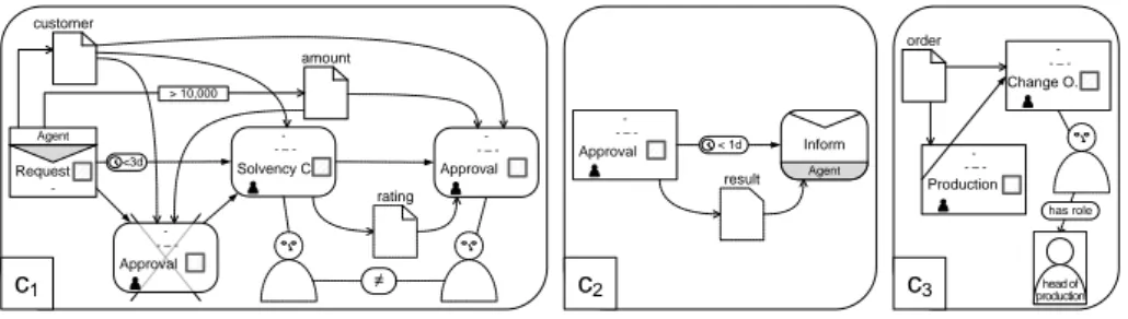
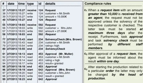
As example consider the event log from Fig. 2, which refers to an order-to- delivery process [5]: Compliance rulec1, shown on the right, is satisfied in one case, but violated in another. In particular, the depicted log refers to two differ- ent request items related to customers Mr. Smithand Mrs. John. These items, in turn, trigger two different instances of compliance rule c1. In both cases, the amount is greater than 10,000eand hence a solvency check is required (cf.c1).
However, the latter was only performed for the request item of Mr. Smith, but not for the one of Mrs. John, i.e.,c1 is violated in the latter case. In addition to the violation of c1, compliance rule c2 is violated twice. While the violated
# date time type id details 37 1/7/2013 15:27 receive 124 Request 38 1/7/2013 15:27 write 124 customer = Mr.Smith 39 1/7/2013 15:27 write 124 amount = 15.000€
40 1/7/2013 15:27 end 124 Request 55 1/7/2013 18:03 receive 592 Request
56 1/7/2013 18:03 write 592 customer = Mrs.John 57 1/7/2013 18:03 write 592 amount = 27.000€
58 1/7/2013 18:03 end 592 Request
77 2/7/2013 15:43 start 234 SolvencyCheck (Mrs. Brown) 78 2/7/2013 15:43 read 234 customer = Mr.Smith 79 2/7/2013 15:54 write 234 rating= high 80 2/7/2013 15:55 end 234 SolvencyCheck 91 2/7/2013 18:13 start 453 Approval (Mr. Muller) 92 2/7/2013 18:14 read 453 customer = Mr.Smith 93 2/7/2013 18:14 read 453 rating = high 94 2/7/2013 18:17 write 453 result = granted 95 2/7/2013 18:18 end 453 Approval
96 2/7/2013 18:19 start 642 Approval (Mrs. Brown) 97 2/7/2013 18:20 read 642 customer = Mrs.John 98 2/7/2013 18:23 write 642 result = granted 99 2/7/2013 18:23 end 642 Approval
When a request item with an amount greater than 10,000 is received from an agent, the request must not be approved unless the solvency of the respective customer is checked. The latter task must be started at maximum three days after the receipt. Furthermore, task approval and task solvency check must be performed by different staff members.
After approval of a request item, the agent must be informed about the result within one day.
After starting the production related to a particular order the latter may only be changed by the head of production.
c1
c2
c3
Compliance rules
...............
Fig. 2: Event log of order-to-delivery processes and compliance rules
instance of rulec1 will never be successfully completed, the violations ofc2 still may be healed by informing the agent about the results of the approvals. The compliance rule examples further indicate that solely monitoring control flow dependencies between tasks is not sufficient to ensure compliance at run time.
In addition, constraints with respect to the data, time, and resource perspectives of a business process as well as the interactions this process has with partner processes need to be monitored as well [6–9]. For example, the data perspective of compliance rulec1 is addressed by the request item and itsamount. In turn, receiving the request item (cf.c1) corresponds to an interaction with a business partner. Furthermore, the phrase ”by different staff members” deals with the resource perspective, whereas the condition ”at maximum three days” refers to the time perspective. To meet practical demands, compliance monitoring must not omit these process perspectives.
Altogether, the following requirements need to be addressed:
RQ1.As a fundamental challenge of any compliance monitoring approach, com- pliance violations must be reliably detected and reported to the appropriate parties by using alerts, emails, text messages, or other notification mechanisms.
Furthermore, compliance-aware user guidance is needed to avoid rule violations.
RQ2. Since compliance is not restricted to the control flow perspective solely, the time, resource and data perspectives of a business process as well as its interactions with business partners need to be considered during compliance monitoring as well.
RQ3. In general, the execution of a business process may trigger multiple in- stances of the same compliance rule. On one hand, this highlights the need for being able to identify the causes of a specific compliance violation as well as for providing proper user feedback [10]. On the other, this mightlead to situations in which a compliance rule is fulfilled or violated multiple times in the context of a particular process instance. Accordingly, any compliance assessment must reflect the relation between fulfilled and violated instances of compliance rules.
RQ1-RQ3 cover the essentialcompliance monitoring functionalities (CMFs) as proposed in [4]. Therefore, they may be used to compare existing approaches for monitoring business compliance. However, [4] also states that existing ap- proaches only partially meet the CMFs. In particular, the combination of an ex- pressive language (RQ2) and full traceability (RQ3) is not well understood yet.
This paper extends the work, we presented in [5] in order to provide a com- prehensive framework addressing RQ1-RQ3. In particular, it adds detailed algo- rithms for compliance rule monitoring based on the visualextended Compliance Rule Graph (eCRG) language [8, 9]. The current state of a particular eCRG is reflected through a set of visual rule markings. The latter not only indicate com- pliance violations, but may also be utilized for recommending the next process tasks to be executed to ensure compliance (RQ1). Furthermore, these markings allow us to clearly differ between fulfilled and violated instances of an eCRG and also provide a suitable basis for compliance metrics (RQ3). Note that the eCRG language supports the time, resource and data perspectives as well as interactions with business partners (RQ2). We evaluate the algorithms based on
OccurenceAbsence
Antecedence Consequence
Task
Task Task
Task
Data Object Data Object Data Nodes
AntecedenceConsequence
Group Organizational
Staff Unit
Member Role
Group Organizational
Staff Unit
Member Role
Resource Nodes
Requests Request Particular Data Nodes
Quality Managers
Radiology Department Computer
Scientist Mr X
Antecedence Consequence Time Conditions
>2d >2d March 23th
2013 Point in Time Extended Compliance Rule Graph Language (eCRG)
Process Perspective Time Perspective
Resource Perspective Data Perspective
< value
> value Antecedence
Consequence Data Conditions
AntecedenceConsequenceParticular Resources
Antecedence Consequence Antecedence Consequence
Sender
Receiver Message
Message
Sender Message Receiver
Message
Sender
Receiver Message
Message
Sender Message Receiver
Message
Receive Send
OccurenceAbsence
Interaction Perspective
Sequence Exclusion Antecedence
Alternative Basic Connectors
Sequence Exclusion Consequence
Alternative
property property Antecedence
Consequence Resource Conditions
Data Container
Data Container Resource Connectors
Time Nodes
Performing Relation Antecedence
assigned to
Performing Relation Consequence
assigned to
Data Connectors
Data Flow Antecedence
Data Flow Consequence
Knuplesch, Reichert, Ly, Kumar, Rinderle- Ma: Visual Modeling of Business Process Compliance Rules with the Support of Multiple Perspectives. In: ER 2013, LNCS, Springer (2013), pp. 106-120
Fig. 3: Elements of the eCRG language [8, 9]
a proof-of-concept prototype, which was also applied to real world compliance scenarios we had obtained from one of our case studies in the healthcare domain [9].
The remainder of this paper is organized as follows: Section 2 introduces the extended Compliance Rule Graph (eCRG) language. The monitoring framework as well as algorithms that manage the markings of an eCRG are introduced in Section 3. Section 4 validates the framework and presents its proof-of-concept prototype. Section 5 discusses related work. Section 6 concludes the paper and provides an outlook on future research.
2 Fundamentals
This paper utilizes the extended Compliance Rule Graph (eCRG) language we developed for modeling compliance rules [8, 9]. The eCRG language is based on the Compliance Rule Graph (CRG) language [10]. As opposed to CRG, eCRG not only focuses on the control flow perspective, but also provides integrated support for the resource, data and time perspectives as well as for the interactions with business partners. To cover the various perspectives, the eCRG language allows forattachments in addition tonodes and connectors (i.e. edges). Nodes, connectors and attachments may be partitioned into anantecedence pattern and one or several related consequence patterns. Both patterns are modeled using occurrence andabsence nodes, which either express the occurrence or absence of certain events (e.g. related to the execution of a particular task) or which refer to process entities (e.g. data objects). In turn, edges and attachments are used to
Agent
rating
≠ Request
Approval - - – -
Approval - - – - Solvency C.
- - – - -
c1 customer
amount
> 10,000
Agent Inform Approval
- - – -
< 1d result
c2
Change O.
- - – -
Production - - – -
head of production
c3
has role order
<3d
Fig. 4: Modeling compliance rulesc1−c3with the eCRG language
refine the specification of the elements they are affiliated to (e.g., by specifying control flow dependencies). Furthermore, an eCRG may containinstance nodes referring to particular objects that exist independently from the respective rule (e.g.Mr. Smith,postnatal ward,physician). Note that instance nodes are neither part of the antecedence nor the consequence pattern. Fig. 3 provides an overview of eCRG elements, which are applied in Fig. 4 to model the compliance rules from Fig. 2. In this paper, we refer to the following elements of an eCRG:
– Nodes: These include, for example, TaskNodes, MessageNodes, PointInTi- meNodes,DataObjects, andResourceNodes.
– Edges: These include, for example,SequenceFlowEdges,DataFlowEdges,Per- formingEdges,ResourceRelations, and DataRelations.
– Attachments: These include, for example, DataConditionAttachments, Re- sourceConditionAttachments, andTimeConditionAttachments.
In this context, two elements a and b of an eCRG have the same dependency level (a≜b), if they are elements of the same pattern. In turn, an attachment or edge c corresponds to a noded, if c directly or indirectly constrains d. Finally, set Λ ∶=Nodes∪Edges∪Attachments contains all elements of an eCRG. For a more formal eCRG specification, we refer to [11, 12].
3 eCRG Compliance Monitoring
This section introduces the framework for visually monitoring multiple perspec- tives of business process compliance at runtime. As discussed in Sect. 1, compli- ance monitoring is based on streams of events occurring during the execution of business processes. In particular, it aims to determine or prevent compliance vio- lations. For this purpose, the framework annotates and marks the elements of an eCRG with text, colors and symbols during the processing of events. These mark- ings not only provide a basis for determining the state of compliance of a partic- ular rule, but also highlight the causes of occurring compliance rule violations.
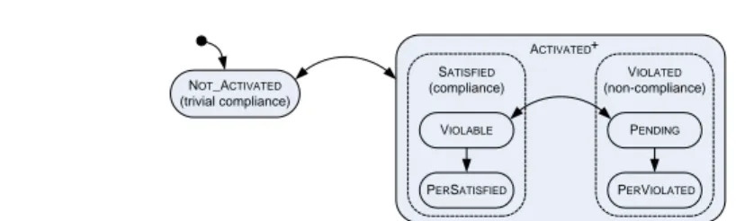
States of Compliance Rules. When monitoring the compliance of running pro- cesses, compliance rule instances may be in different states. Fig. 5 outlines the
ACTIVATED
VIOLATED (non-compliance) SATISFIED
(compliance) VIOLABLE
PERSATISFIED
PENDING
PERVIOLATED NOT_ACTIVATED
(trivial compliance)
+
Fig. 5: States of compliance rules
states supported by the framework. The most fundamental state isNot Activa- ted, i.e., the compliance rule does not apply to the running process instance so far. In turn, stateActivatedexpresses that the compliance rule is applicable to the process instance. Furthermore, this state includes the sub-statesSatisfied and Violated (cf. Fig. 5). State Satisfied is further partitioned into sub- statesViolableandPerSatisfied(i.e., permanently satisfied), whereas state Violatedincludes sub-states Pending and PerViolated(i.e., permanently violated). As explained in the context of the example, business processes may trigger (i.e. activate) multiple instances of a compliance rule. Hence, a compli- ance rule may be in stateActivatedmultiple times as indicated by superscript
”+” in Fig. 5. However, each of theseactivations of a compliance rule may be in a different sub-state. For example, the event log of the example from Fig. 2 activates compliance rule c1 twice (cf. Fig. 2). While the first activation is in statePerSatisfied, the second one is in final statePerViolated.
Events. As the framework enables compliance monitoring for multiple process perspectives (cf. RQ2), it not only monitors events referring to the start and end of tasks. In addition, it considers events that correspond to the sending and receiving of messages as well as data flow events. Furthermore, events may include temporal information as well as information about involved resources.
Table 1 summarizes the event types supported by the framework. Each entry refers to the time the event occurred and to a unique identifier. The latter enables us to correlate start, end and data flow events of the same task or message. Note that we presume correct event streams; i.e., they do not deviate from the real process. Further, events are provided in ascending order.
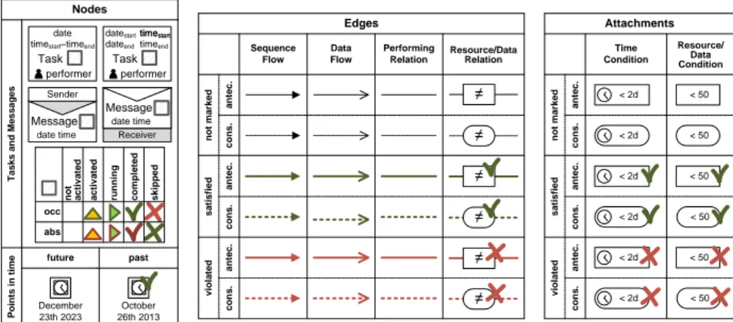
eCRG Markings. To monitor the state of a compliance rule, we mark the ele- ments of an eCRG (cf. Sect. 2, [8, 9]) with symbols, colors and text (cf. Fig. 6).
Such amarking of an eCRG highlights whether or not the events corresponding to a node have occurred so far. Further, a marking describes whether conditions corresponding to edges and attachments are satisfied, violated, or still may be evaluated.
Table 1: Supported Events
Task events Message events Data flow events start(time, id, tasktype, performer) send(time, id, message) write(time, id, valueÐÐÐÐ→paramsource)
end(time, id, tasktype, performer) receive(time, id, message) read(time, id, value←ÐÐÐÐparamsource) end(time, id, message)
Points in timeTasks and Messages not activated skipped
completed
running
activated
abs occ Task date
performer timestart–timeend
Sender
Message date time
Task performer dateend timeend datestart time timestartstart
Receiver
Message
date time
December 23th 2023
future
October 26th 2013 past
< 2d
< 2d
antec.cons.
< 2d
< 2d
< 2d
< 2d < 50 < 50
< 50 < 50 < 50 < 50
satisfied
Time Condition
Resource/
Data Condition
not marked
Attachments
antec.cons.antec.cons.
antec.cons.
≠
≠
≠
≠
≠
≠
satisfied
Sequence Flow
Data Flow
Performing Relation
Resource/Data Relation
not marked
Edges
antec.cons.antec.cons. violated
violated
Nodes
Fig. 6: Fundamental markings of eCRG elements
LetRbe the set of resources,Ω be the set of data objects,I be the set of identifiers, andTbe the set of point in times. Further, letbe theempty value.
Then: A markingM can be described with the following functions:
– M.mark∶Λ→ {◻ =,△,▶,✓,⨉}marks the elements of the eCRG as not- marked ◻,activated △,running ▶,satisfied (orcompleted)✓, andviolated (orskipped)⨉(cf. Fig. 6),
– M.res∶Λ→ R ∪ {} assigns resources to the elements of the eCRG, – M.val∶Λ→Ω∪ {}assigns values to each element of the eCRG,
– M.id∶Λ→ I ∪ {} assigns unique identifiers to the elements of the eCRG, – M.start(M.end) ∶Λ→T∪{}assigns starting (ending) times to the elements.
The functions of the initial marking 0 assign (and ◻ respectively) to all elements of an eCRG, except the ones of theinstance pattern that are mapped to the particular resource, data value or point in time they refer to. Since there may be multiple activations of a particular compliance rule, thestate of an eCRG is a setMof markings.
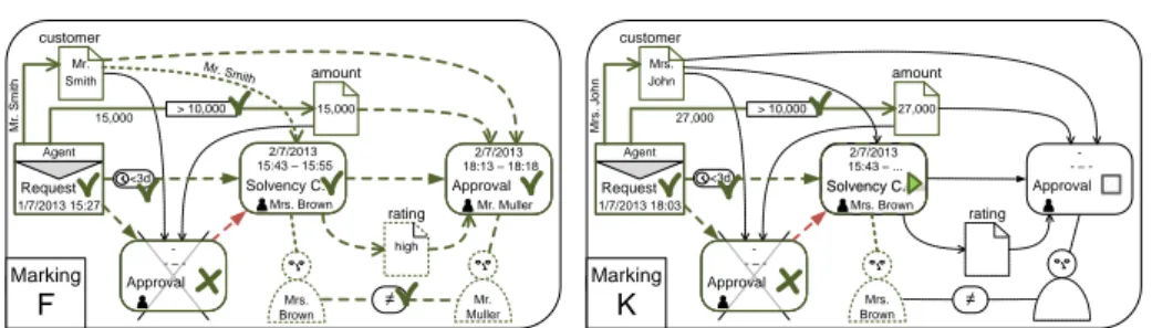
Fig. 7 shows two markings for compliance rule c1 from Fig. 2. On the left, markingF highlights the fulfillment ofc1 for the request of Mr. Smith. In turn, markingK on the right emphasizes how markings support users in proactively ensuring compliance. In particular,K indicates which data values the tasksol- vency check shall read and how task approval shall be performed afterwards in order to satisfyc1.
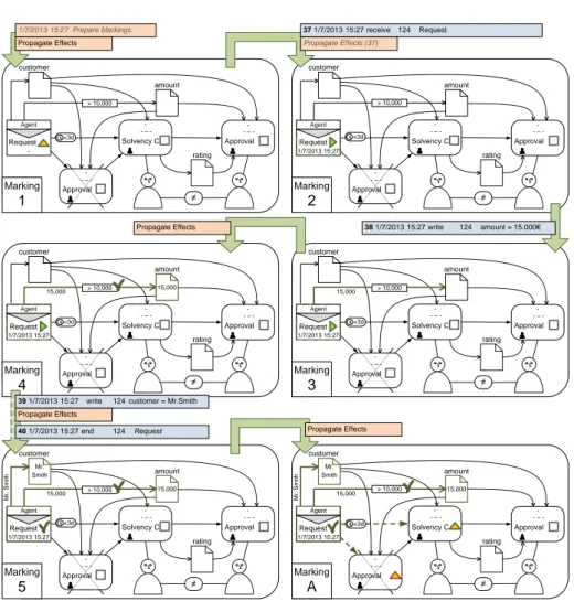
Event Processing. This section describes the processing of events with an eCRG.3 Fig. 8 provides an overview. First, all markings are prepared for the processing.
Second, effects of these preparations (i.e., changed markings) are propagated onto connected elements. Third, the actualevent handling takes place. Fourth,
3 [11] provides a formal specification of the operational semantic of the eCRG language.
Agent
rating
≠ Request
Approval - - – -
Approval 2/7/2013
Mr. Muller 18:13 – 18:18 Solvency C.
2/7/2013
Mrs. Brown 15:43 – 15:55 1/7/2013 15:27
F
customer Mr.
Smith amount
15,000
Mr. Smith
15,000 > 10,000
Mr. Smith
high
<3d
Mrs.
Brown
Mr.
Muller
Marking
F
Agent
rating
≠ Request
Approval - - – -
Approval - - – - Solvency C.
- - – - 1/7/2013 18:03
d2
customer Mrs.
John amount
27,000
Mrs. John
27,000 > 10,000
Solvency C.
2/7/2013
Mrs. Brown 15:43 – ...
<3d
Mrs.
Brown
Marking
K
Fig. 7: Examples of markings for compliance rulec1
Prepare Markings
Propagate Effects
Handle StartEvent
Handle
MessageEvent Propagate
Effects
Handle EndEvent
Handle DataEvent start(…)
end(…) receive(…) send(…) read(…) write(…)
Fig. 8: Processing of start, message, data, and end events
effects of the latter step are propagated to connected elements as well. Note that the first two steps may be applied without the last two ones, e.g., to calculate the current state of a compliance rule at an arbitrary point in time.
In general, not only the occurrence of events, but also elapsing time can violate compliance, e.g, when the maximum time distance between two tasks becomes violated. To ensure that related issues are not ignored, Listing 1 updates the time perspective of markings before the latter process an event. In particular, point in time nodes are changed to✓, if they lie in the past now, whereas time condition attachments on task nodes or sequence flow edges are skipped (⨉) if they are no longer satisfiable.
Listing 2 deals with the handling of start and message events. In particular, markings of activated task or message nodes, which match the event, are re-set from△to▶. Accordingly, identifiers, resources and starting times are set. Note
Listing 1:Prepare Markings (with respect to the time perspective)
1 prepareMarking(M,event(time,. . . ))
2 ForEach(pitn∈PointInTimeNodeswithM.mark(pitn) = ◻)
3 If(pitn≤time ) M.mark(pitn) ∶= ✓;
4 ForEach(tc∈TimeConditionAttachmentswithM.mark(tc) = ◻)
5 If(tcis attached totn∈TaskNodesandM.mark(tn) = ▶)
6 If(∀t≥time∶tc(ts(t), t) =false)M.mark(tc) ∶= ⨉;
7 ElseIf(tcis attached tosf= (n1, n2) ∈SequenceFlowEdgesandM.mark(n1) = ✓)
8 If(∀t≥time∶tc(te(n1), t) =false)M.mark(tc) ∶= ⨉;
9 ReturnM;
Listing 2:Handle Events
1 handleStartEvent(M,start/send/receive(time, id, type,performer))
2 M ∶= ∅;
3 ForEach(σ⊆ {tn∣tn∈TaskNodesandM.mark(tn) = △andtypeOf(tn) =type})
4 ForEach(tn∈σ)
5 M′∶=copy(M);
6 M′.mark(tn) ∶= ▶;M′.start(tn) ∶=time;
7 M′.id(tn) =id;M′.res(tn) ∶=performer;
8 M ∶= M ∪ {M′};
9 ReturnM;
10 handleMessageEvent(M,send/receive(time, id, type))
11 M ∶= ∅;
12 ForEach(σ⊆ {tn∣tn∈MessageNodesandM.mark(tn) = △andtypeOf(tn) =type})
13 ForEach(tn∈σ)
14 M′∶=copy(M);
15 M′.mark(tn) ∶= ▶;M′.start(tn) ∶=time;M′.id(tn) =id; ;
16 M ∶= M ∪ {M′};
17 ReturnM;
18 handleEndEvent(M,end(time, id, type, performer))
19 ForEach(tn∈TaskNodeswithM.id(tn) =id)
20 M.mark(tn) ∶= ✓;M.end(tn) ∶=time;
21 Return{M};
22 handleDataEvent(M,write/read(time, id, valueÐÐÐÐ→param source))
23 ForEach(df= (n, x) ∈DataflowEdgeswithM.id(n) =id andM.mark(n) = ▶)
24 If(typeOf(df) =param)
25 M.mark(df) ∶= ✓;M.val(df) ∶=value;
26 Return{M};
that start and message events are handled non-deterministically; i.e., the changes are applied to copies of the original marking that is maintained (cf. Fig. 9.2).
Further, Listing 2 specifies the handling of data events. In particular, the cor- responding data flow edges of running task (message) nodes are annotated with the data value passed (cf. Figs. 9.4 and 9.5). Finally, the handling of end events is addressed in Listing 2 as well. In particular, the markings of corresponding nodes in state running (▶) are set to completed (✓); their ending time is set accordingly. (cf. Fig. 9.A)
Effects of preparing and handling events must be propagated to ensure correct markings (e.g., activation of subsequent task nodes) as well as to detect contra- dictory markings related to the data and resource perspectives. In particular, data values are propagated along data flow edges to connected data objects. In turn, resources are propagated from task nodes via resource edges to connected resource nodes. The propagation fails, if a resource or data object node is set to a different value before. In this case, the respective edge is skipped (⨉). Further- more, conditions and relations are evaluated as soon as possible. If any element of the eCRG, which corresponds to a task or message node, becomes skipped (e.g., due to a failed data or resource propagation, or a violated condition), the task or message node will be skipped as well. Then, outgoing sequence flows of
Marking
4
Agent
rating
≠ Request
Approval - - – -
Approval - - – - Solvency C.
- - – - -
customer
amount
> 10,000
Agent
rating
≠ Request
Approval - - – -
Approval - - – - Solvency C.
- - – - 1/7/2013 15:27
customer
amount
> 10,000 371/7/2013 15:27 receive 124 Request
<3d <3d
1/7/2013 15:27 Prepare Markings
Propagate Effects Propagate Effects (37)
Agent
rating
≠ Request
Approval - - – -
Approval - - – - Solvency C.
- - – - 1/7/2013 15:27
a2
customer
amount
15,000 > 10,000
<3d
381/7/2013 15:27 write 124 amount = 15.000€
Agent
rating
≠ Request
Approval - - – -
Approval - - – - Solvency C.
- - – - 1/7/2013 15:27
customer Mr.
Smith amount
15,000
Mr. Smith
15,000
Agent
rating
≠ Request
Approval - - – -
Approval - - – - Solvency C.
- - – - 1/7/2013 15:27
A
customer Mr.
Smith amount
15,000
Mr. Smith
15,000
> 10,000 > 10,000
<3d <3d
Agent
rating
≠ Request
Approval - - – -
Approval - - – - Solvency C.
- - – - 1/7/2013 15:27
customer
amount
15,000 > 10,000
<3d
15,000 Propagate Effects
Propagate Effects 401/7/2013 15:27 end 124 Request
391/7/2013 15:27 write 124 customer = Mr.Smith Propagate Effects
Marking
1
Marking
2
Marking
3
Marking
5
Marking
A
Fig. 9: Handling of events
completed nodes will be marked as satisfied (✓). In turn, non-marked incoming edges of already started nodes as well as edges from and to skipped nodes will be skipped. Task and message nodes will be activated (△) when all incoming sequence flows, these nodes depend on, are satisfied. In turn, task or message nodes will be skipped (⨉) if they depend on sequence flows being skipped as well.
Note that the latter might result in the cascading skipping of other sequence flow edges (cf. Listing 3).
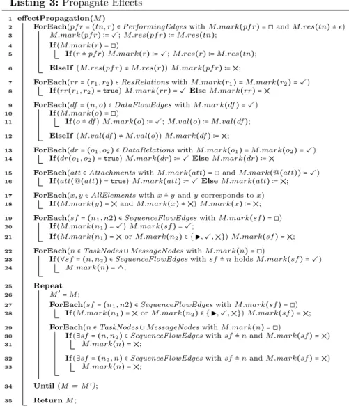
Table 2 illustrates the set of markings that results after processing the event stream from Fig. 2 for compliance rulec1. In turn, Figs. 10-13 highlight conflicts regarding the data (Fig. 10), control flow (Fig. 12), resource (Fig. 11), and time (Fig. 13) perspectives. Note that conflicting markings only highlight why the considered events do not constitute a fulfillment of a particular compliance rule, but they do not necessarily lead to a violation of the latter.
Listing 3:Propagate Effects
1 effectPropagation(M)
2 ForEach(pf r= (tn, r) ∈PerformingEdgeswithM.mark(pf r) = ◻andM.res(tn) ≠)
3 M.mark(pf r) ∶= ✓;M.res(pf r) ∶=M.res(tn);
4 If(M.mark(r) = ◻)
5 If(r≜pf r)M.mark(r) ∶= ✓;M.res(r) ∶=M.res(tn);
6 ElseIf(M.res(pf r) ≠M.res(r))M.mark(pf r) ∶= ⨉;
7 ForEach(rr= (r1, r2) ∈ResRelationswithM.mark(r1) =M.mark(r2) = ✓)
8 If(rr(r1, r2) =true)M.mark(rr) = ✓ElseM.mark(rr) = ⨉
9 ForEach(df= (n, o) ∈DataFlowEdgeswithM.mark(df) = ✓)
10 If(M.mark(o) = ◻)
11 If(o≜df)M.mark(o) ∶= ✓;M.val(o) ∶=M.val(df);
12 ElseIf(M.val(df) ≠M.val(o))M.mark(df) ∶= ⨉;
13 ForEach(dr= (o1, o2) ∈DataRelationswithM.mark(o1) =M.mark(o2) = ✓)
14 If(dr(o1, o2) =true)M.mark(dr) ∶= ✓ElseM.mark(dr) ∶= ⨉
15 ForEach(att∈AttachmentswithM.mark(att) = ◻andM.mark(@(att)) = ✓)
16 If(att(@(att)) =true)M.mark(att) ∶= ✓ElseM.mark(att) ∶= ⨉;
17 ForEach(x, y∈AllElementswithx≜yandycorresponds tox)
18 If(M.mark(y) = ⨉andM.mark(x) ≠ ⨉)M.mark(x) ∶= ⨉;
19 ForEach(sf= (n1, n2) ∈SequenceFlowEdgeswithM.mark(sf) = ◻)
20 If(M.mark(n1) = ✓)M.mark(sf) = ✓;
21 If(M.mark(n1) = ⨉orM.mark(n2) ∈ {▶,✓,⨉})M.mark(sf) = ⨉;
22 ForEach(n∈TaskNodes∪MessageNodeswithM.mark(n) = ◻)
23 If(∀sf= (n, n2) ∈SequenceFlowEdgeswithsf≜nholdsM.mark(sf) = ✓)
24 M.mark(n) = △;
25 Repeat
26 M′=M;
27 ForEach(sf= (n1, n2) ∈SequenceFlowEdgeswithM.mark(sf) = ◻)
28 If(M.mark(n1) = ⨉orM.mark(n2) ∈ {▶,✓,⨉})M.mark(sf) = ⨉;
29 ForEach(n∈TaskNodes∪MessageNodeswithM.mark(n) = ◻)
30 If(∃sf= (n, n2) ∈SequenceFlowEdgeswithsf≜nandM.mark(sf) = ⨉)
31 M.mark(n) = ⨉;
32 If(∃sf= (n2, n) ∈SequenceFlowEdgeswithsf≜nandM.mark(sf) = ⨉)
33 M.mark(n) = ⨉;
34 Until(M = M’ );
35 ReturnM;
Compliance assessments and metrics. Based on the described set of markings, we can identify the different activations of an eCRG and derive their state of compliance. In turn, activations correspond to the minimal markings, which satisfy the antecedence pattern, but do not satisfy any element of the antecedence absence pattern (cf. Sect. 2). In particular, an activation is satisfied if there exists another marking extending the activation and satisfying the consequence pattern. We omit a formal specification here and refer to [11] instead.
Table 3 highlights the properties of both activated markingsAandB along the log from Fig. 2. In particular, Table 3 shows that c1 is activated twice;
once satisfied and once violated. Furthermore, Table 3 indicates the events that complete the activations (39 and 58), the fulfillment (95), and the violation (99).
Table 2: Markings after processing the event log from Fig. 2
Request Approval Solvency Approval cust. cust.→ cust.→amount rating
# (CA) Check (CO) App.(CA) Solv.C
1 △ ◻ ◻ ◻
A!✓ 124 △ △ ◻ Smith 15.000
B!✓ 592 △ △ ◻ John 27.000
C ✓ 124 ⨉ ✓ 234 Brown△ Smith Smith 15.000 high
D ✓ 592 △ ⨉ 234 Brown ⨉ John Smith 27.000
E ✓ 592 ⨉453 Muller△ ◻ John Smith 27.000
F ✓ 124 ⨉ ✓ 234 Brown✓453 Muller Smith Smith 15.000 high
G ✓ 124 ✓453 Muller△ ◻ Smith Smith 15.000 high
H ✓ 124 ⨉ ✓ 234 Brown ⨉642 Brown Smith Smith 15.000
I ✓ 592 ✓642 Brown△ ◻ John John 27.000
J ✓ 124 ⨉642 Brown△ ◻ Smith John 25.000
Agent
Mrs.
Brown rating
≠ Request
Approval - - – -
Approval - - – - Solvency C.
2/7/2013
Mrs. Brown 15:43 – ...
1/7/2013 18:03 customer Mrs.
John amount
27,000
Mrs. John
27,000 > 10,000
Mr. Smith
<3d
Marking
D
Fig. 10: Data conflict
Agent
rating
≠ Request
Approval - - – -
Approval 2/7/2013
Mrs. Brown 18:19 – ...
Solvency C.
2/7/2013
Mrs. Brown 15:43 – 15:55 1/7/2013 15:27
J
customer Mr.
Smith amount
15,000
Mrs. Smith
15,000 > 10,000
Mr. Smith
high
<3d
Mrs.
Brown
Mrs.
Brown
Marking
J
Fig. 11: Resource conflict
Agent
rating
≠ Request
Approval 2/7/2013 18:19 – 18:23
Approval - - – - Solvency C.
- - – - 1/7/2013 15:27
I
customer Mrs.
John amount
27,000
Mrs. John
27,000 > 10,000
<3d
Mrs. Brown
Mrs. John 27,000
Marking
I
Fig. 12: Control flow conflict
Agent
Mrs.
Brown rating
≠ Request
Approval - - – -
Approval - - – - Solvency C.
- - – - 1/7/2013 18:03
B‘
customer Mrs.
John amount
27,000
Mrs. John
27,000 > 10,000
<3d
Marking
L
Fig. 13: Time conflict
Note that it is easy to specify metrics based on the states of compliance based on the number of activated markings in a particular compliance state Property:
#(M,Property) ∶= ∣{M ∈ M∣Property(M)}∣; e.g., Table. 3 refers to the compliance rate µ1∶=##(M(M,,Activated)Satisfied) and
critical rate µ2∶= #(M,Violable)+#(M,Activated)#(M,Pending).
Table 3: Compliance assessments and metrics
# ExtensionsActivated Violable Pending PerSatisf.PerViol. A {C,F,G,J} 39-. . . 39-95 95-. . .
B {D,E,H,I} 58-. . . 58-99 99-. . .
date time µ1 µ2 1/7/2013 15:00 n.d. n.d.
2/7/2013 15:00 0% 100%
2/7/2013 18:18 50% 50%
2/7/2013 19:00 50% 0%
4 Evaluation
The eCRG language has been evaluated with respect to different aspects (cf. [8, 12]). In particular, its expressiveness allows modeling different sets of compliance patterns (e.g. [13]). In turn, a case study in the medical domain revealed that a business analyst was able to properly use eCRG [9]. Finally, current empirical studies indicate that there isno significant differencebetween computer experts and business analysts in understanding eCRGs.
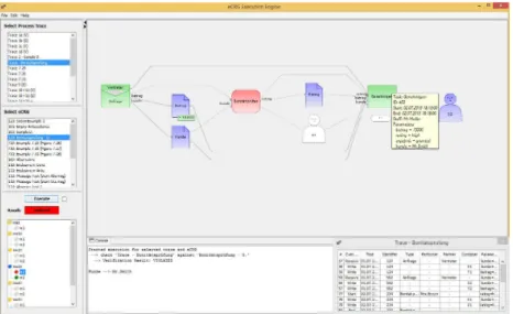
To verify the feasibility of the presented compliance monitoring framework, we implemented an advanced proof-of-concept prototype [14]. The latter incre- mentally processes event logs, unfolds the markings (cf. Sect. 3), and visualizes them. Note that the prototype supports additional features, not discussed in this paper due to space limitations; e.g., beyond end-start control flow constraints, start-start, start-end, and end-end constraints are supported as well. We applied the prototype to different scenarios including the presented order-to-delivery ex- ample as well as real world compliance scenarios obtained in the context of a case study in the healthcare domain [9]. Note that the benefits of the framework come with the cost of a high, up-to exponential computational complexity of O(∣Events∣∣Nodes∣). Fig. 14 provides a screenshot of the eCRG execution engine.
5 Related Work
In recent years, business process compliance has gained increasing attention and several surveys have been provided [15, 7, 16]. Accordingly, interest in compli- ance monitoring andcontinous auditing [17] has increased as well. [18] enriches process models with a semantic layer of internal controls. In [19, 20], the detailed architecture of an online auditing tool (OLAT) is described. The latter allows
Fig. 14: Proof-of-concept implementation
Table 4: Compliance Monitoring Functionalities [4]
CMF 1 CMF 2 CMF 3 CMF4 CMF 5 CMF 6 CMF 7 CMF 8 CMF 9 CMF 10 time data resources non life- multi- reactive proactive root compl.
Approach atomic cycle instance mgmt mgmt cause degree
Mubicon LTL [24] +/- - - + - - + + + +/-
Mubicon EC [36] + +/- + + + + + - +/- +/-
ECE Rules [37] + +/- + + - - + - +/- +
SCT [22] +/- - + + + - - + - -
SeaFlows [10] +/- +/- +/- + +/- + + + + +/-
eCRG Monitoring + + + + + + + + + +
monitoring the operations of an organization in detective, corrective and preven- tive modes. The broad spectrum of techniques enabling compliance monitoring include behavioural profiles [21] (i.e., to utilize ordering relations), Supervisory Control Theory [22] (i.e., to prevent from actions leading to compliance viola- tions), and visual declarative constraints [23], which are transformed intoEvent Calculus and LTL. To enable fine-grained compliance diagnostics at run-time, Compliance Rule Graphs [10] and colored automata [24] are utilized, focusing on control flow. Finally, [4] compares approaches for monitoring business compli- ance based on 10compliance monitoring functionalities (CMF). In particular, it emphasizes that none of the existing approaches provides a satisfactory solution that combines an expressive language with full traceability (cf. RQ2+RQ3). In turn, the presented approach for monitoring compliance with the eCRG language supports all 10 CMFs (cf. Table 4) [4].
However, [25, 13, 26]a posterioriverify the compliance of execution logs with a set of constraints. Some approaches not only focus on the control flow perspec- tive, but consider other perspectives as well.A priori ordesign time compliance checking is addressed by a multitude of approaches, which commonly apply model checking; e.g., [27–30]. Some of them use visual compliance rules and ad- dress multiple perspectives. To specify compliance rules, formal languages (e.g., LTL [28]), pattern-based approaches (e.g., [31, 13]) are applied. Further, visual notations [27, 10] as well as methodologies to relate the latter with informal and textual specifications [32] have been proposed. Note that declarative languages [33, 34] can be also applied to specify compliance rules. Finally, the integration of business process compliance throughout the entire process lifecycle [2, 3] as well as monitoring of performance measures in the context of artifact-centric process models in real-time [35] have been addressed.
6 Summary and Outlook
In recent years, business process compliance has gained an increasing interest. A multitude of approaches focus on compliance monitoring at run time [18, 17, 19, 10, 24, 36]. However, existing approaches do not provide a satisfactory solution that combines an expressive language with full traceability [4].
To remedy this drawback, we proposed, developed and demonstrated a com- pliance monitoring framework that utilizes the extended compliance rule graph (eCRG) language, which enables the visual modeling of compliance rules with
![Fig. 3: Elements of the eCRG language [8, 9]](https://thumb-eu.123doks.com/thumbv2/1library_info/5212901.1669033/4.892.202.720.162.488/fig-elements-ecrg-language.webp)