Software & Systems Modeling manuscript No.
(will be inserted by the editor)
A Visual Language for Modeling Multiple
Perspectives of Business Process Compliance Rules
David Knuplesch and Manfred Reichert
Received: 8 October 2014 / Revised: 21 December 2015 / Accepted: 3 March 2016
Abstract A fundamental challenge for enterprises is to ensure compliance of their business processes with imposed compliance rules stemming from various sources, e.g., corporate guidelines, best practices, standards, and laws. In gen- eral, a compliance rule may refer to multiple process perspectives including control flow, time, data, resources, and interactions with business partners.
On one hand, compliance rules should be comprehensible for domain experts who must define, verify and apply them. On the other, these rules should have a precise semantics to avoid ambiguities and enable their automated process- ing. Providing a visual language is advantageous in this context as it allows hiding formal details and offering an intuitive way of modeling the compli- ance rules. However, existing visual languages for compliance rule modeling have focused on the control flow perspective so far, but lack proper support for the other process perspectives. To remedy this drawback, this paper in- troduces the extended Compliance Rule Graph language, which enables the visual modeling of compliance rules with the support of multiple perspectives.
Overall, this language will foster the modeling and verification of compliance rules in practice.
Keywords business process compliance, extended compliance rule graphs, business process modeling, smart processes
1 Introduction
During the last decades a variety of techniques for verifying the correctness of business process models were proposed. While early approaches focused on
David Knuplesch and Manfred Reichert Ulm University,
Institute of Database and Information Systems James-Franck-Ring
89081 Ulm, Germany
E-mail: firstname.familyname@uni-ulm.de
issues related to structural and behavioral model correctness (e.g., absence of deadlocks and livelocks) [1, 84], the semantic correctness of process models with respect to imposed compliance rules (i.e., business process compliance) has been subject to recent works [34, 65, 10, 45]. Compliance rules constrain the execution order (i.e. control flow) of tasks and may originate, for exam- ple, from security constraints, domain-specific guidelines, corporate standards, and legal regulations. Besides the control flow perspective, other fundamental perspectives1 relevant in the context of business process compliance refer to time, data, and resources as well as the interactions a business process has with partner processes [20, 81, 51].
1.1 Problem Statement
In practice, compliance rules are represented in a rather verbose and am- biguous way. To enable the computer-based verification of business process compliance, i.e., to verify that a particular business process meets imposed compliance rules, subject matter experts and business analysts should provide unambiguous descriptions of compliance rules, which then can be translated into a machine-readable representation by IT experts. For the latter purpose, several approaches for the formal specification of compliance rules exist, e.g.
applying linear temporal logics (LTL) [30] or using the formal contract lan- guage (FCL) [33]. As formal rule languages would be too intricate for subject matter experts and business analysts, rule patterns hiding formal details and providing informal explanations were suggested [24, 97, 80, 82]. Although few approaches exist that not only consider the control flow perspective, but also the data, time and resource perspectives, these approaches only support a pre-specified set of rule patterns.
As shown by empirical studies, business process modeling as well as com- pliance rule description languages, which both employ visual notations, offer advantages compared to purely text-based specifications [77, 38]: First, visual notations significantly increase model and rule comprehensibility after pro- viding some training to users. Second, they foster the communication among business analysts and subject matter experts on one hand and process en- gineers on the other. As a prequisite for the computerized support of visual specifications, the latter should be machine-readable, relying on a precise for- mal semantics.
Examples of visual notations for compliance rules include Compliance Rule Graphs [66], BPMN-Q [9], and BPSL [62]. Like visual process modeling lan- guages (e.g., YAWL [3], ADEPT [85] and BPMN [75])2, theses approaches
1 In this paper, the notion ofprocess perspectivecorresponds to a specific business process modeling dimension according to [17].
2 Note that imperative process modeling approaches tend to (over-)specify business pro- cesses. Hence, they are not well suited for specifying declarative constraints and process compliance rules [79, 35, 87].
A Visual Language for Modeling Business Process Compliance Rules 3
combine an intuitive notation with the advantages of a formal language. Ex- isting visual compliance rule languages, however, lack a comprehensive support of the time, data, resource, and interaction perspectives of a business processes, which hinders their use in more sophisticated scenarios.
1.2 Contribution
Although there exist pattern-based approaches for modeling compliance rules also covering the time, data, and resource perspectives, a respective visual modeling support has not been provided so far [80, 97]. To remedy this draw- back, this paper provides an approach for the visual modeling of compliance rules that may refer to these perspectives as well as to the interactions a busi- ness process may have with partner processes. In particular, the paper shows how the various perspectives can be visually represented with the extended Compliance Rule Graph (eCRG) language. We evaluate the expressiveness of the latter based on well-known patterns and apply the eCRG language to a real-world healthcare scenario. Furthermore, understandability issues are con- sidered in an empirical study. Finally, we present a proof-of-concept prototype that supports the modeling of eCRGs as well as their verification. The latter is based on a profound formal semantics of the eCRGs, which is provided in a technical report [49]. Altogether, the eCRG language allows domain experts to capture compliance requirements at both an abstract and a visual level, while enabling the specification of verifiable compliance rules that consider the various perspectives.
This paper significantly extends our previous work, which introduced fun- damentals of the eCRG language [50, 94]: In [50], we provided a very brief overview of the eCRG language, whereas in [94] we focused on the resource perspective solely. In addition to these preliminary works, this paper provides – the first detailed presentation of the eCRG elements covering the interac-
tion, time, data, and resource perspectives,
– an empirical study on the comprehensibility of the eCRG language – a proof-of-concept prototype, which comprises a modeling environment as
well as an eCRG compliance checker verifying the compliance of given process execution logs with a set of eCRGs, and
– an extended and more profound discussion of related work.
The remainder of the paper is organized as follows: Section 2 provides an application scenario from the healthcare domain, which we will use as illus- trating example throughout the paper. In Section 3, we introduce the eCRG language step-by-step. Specifically, this language supports the visual model- ing of compliance rules that may refer to the control flow, interaction, time, data, and resource perspectives. To assess the approach, Section 4 provides a pattern-based evaluation and demonstrates the modeling of real-world com- pliance rules with the eCRG language. Furthermore, it presents an empirical study and the proof-of-concept prototype we developed. Related Work is dis-
cussed in Section 5. Section 6 concludes the paper and provides an outlook on future work.
2 Application Scenario
This section introduces a healthcare scenario dealing with compliance rules and processes captured in the context of a large process engineering project in a university hospital [53, 56]. We will refer to this scenario throughout the paper to illustrate how the elements of the eCRG language can be applied.
woman’s hospital general
practitioner
radiology
function area gynecologist
admission ward unit
postnatal
ward 1 ward 3
ward 2
ward 1 postnatal
ward 2 surgery
department laboratory department
university hospital
blood center
intensive care unit
Mrs. A Mr. B Mr. C
Mrs. G Mr. H Mrs. E
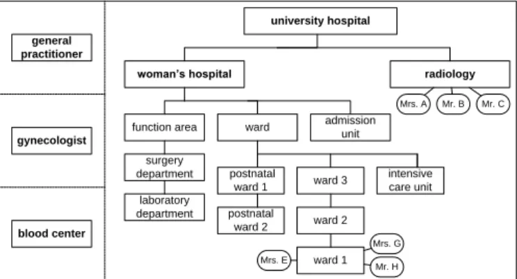
Fig. 1: Organizational units and partners
Selected organizational units and related subunits are depicted in Fig. 1 [53, 56]. On the right, two subunits of theuniversity hospital are shown; i.e., the woman’s hospital, together with its wards (e.g. postnatal ward 1) and service units (e.g.,admission unit), and theradiology department. On the left, external partners of the hospital are depicted, e.g., a gynecologist, a general practitioner, and ablood center.
The example refers to six actors (i.e., Mrs. A, Mr. B, Mr. C, Mrs. E, Mrs. G, and Mr. H) having different roles and being assigned to different organizational units.Mrs. A,Mr. B andMr. C are members of theradiology department, whereasMrs. E,Mrs. G andMr. H are assigned toward 1.Mr.
B and Mrs. E both have rolephysician, whereas Mrs. Ahas role MTA(i.e., medical technical assistant);Mrs. G and Mr. H are nurses andMr. C is the secretary of theradiology department.
Table 1 depicts compliance rules C1 – C10, which emphasize the need for covering the control flow, time, data, and resource perspective of business pro- cesses as well as the interactions a business process has with partner processes.
All rules from Table 1 consider the control flow perspective. For instance, C1 requires the execution of tasksorder X-rayandfill order form prior to the one of taskX-ray examination. C2 states that the documentinformed consent must be received and checked prior to the execution of taskX-ray examination.
A Visual Language for Modeling Business Process Compliance Rules 5
Table 1: Examples of healthcare compliance rules based on [56]
C1 For an inpatient, an X-ray examination must be ordered by award physician. Thesame physician must fill in the respective order form.
C2 An X-ray examination in theradiology departmentmust be performed by aradiologist.
Before, the informed consent of the patient must be received and be checked by amedical technical assistant (MTA)of theradiology department.
C3 Diagnoses shall be provided by physicians only after receiving all X-ray images from theradiology department; i.e.,no X-ray image may be received afterwards.
C4 A patient shall be formally admitted within one week after her referral to the hospital.
C5 At least one day before a surgery takes place, blood bags must be ordered.
C6 Before aphysician requests an informed consent, she or he (i.e., the same physician) must inform the patient about risks.
C7 A period of at least 5 days shall elapse between the administrations of the drugs Aspirin and Marcumar.
C8 For patients older than 75, an additional tolerance test is required prior to the medical examination.
C9 If an additional X-ray examination is ordered to prepare a scheduled surgery, the X-ray must be completed before the surgery.
C10 After 26 October 2013, the duration of a tolerance test must not exceed 30 minutes.
C4 requires that taskrefer patient shall be succeeded by taskadmit patient.
Rules C2 and C3 additionally refer to the interaction perspective of a business process (i.e., the sending and receipt of messages). More precisely, C2 requires the receipt of a message including document informed consent, whereas rule C3 requires waiting for the receipt of a message containing the X-ray images.
The time perspective is considered by rules C4, C5, C7 and C10. Rule C4 defines a maximum time distance between tasksrefer patientandadmit patient (i.e., one week), whereas C5 and C7 specify minimal time distances (see [61, 60] for relevant process time patterns). More precisely, C5 constrains the time minimum distance between tasks order blood bags and surgery, and C7 the minimum time distance between two different occurrences of taskadminister, i.e., one occurrence with drugAspirinand another one with drugMarcumar.
In addition, C10 refers to a fixed point in time; i.e.,26 October 2013.
Rules C2, C7 and C8 constitute examples of compliance rules refering to the data perspective. According to C2, document informed consent needs to be first transmitted through a message and then be checked. Rule C7 expresses that drugs Aspirin and Marcumar are used by task administer. C8 requires an additional tolerance test if the value of data objectage is greater than 75.
Compliance rules C1, C2, C3, and C6 refer to the resource perspective.
On one hand, C1 reflects the resource perspective by requiring the assignment of a performer with rolephysician to the respective ward. On the other, C1 requires that both tasks (i.e.,order X-ray andfill order form) are performed by the same person (i.e., binding of duties). Rule C2 requires performers with different roles being assigned to the same organizational unit. By contrast, C3 solely refers to role physician. Finally, compliance rule C6 provides another example of a binding of duties constraint, i.e., one and the same physician should perform tasksrequest informed consent and inform patient.
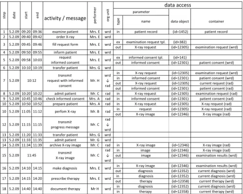
Fig. 2 provides an example of a possible execution log of a healthcare process that shall comply with the rules from Table 1.
type ,
name
1 5.2.09 09:20 09:36 examine patient Mrs. E wrd in patient record (id=1452) patient record 2 5.2.09 09:40 09:42 order X‐ray Mrs. E wrd
ex examination request tpl. (id=382)
out X‐ray request (id=12305) examination request (wrd) 4 5.2.09 09:50 09:55 inform patient Mrs. E wrd
ex informed consent tpl. (id=141)
out informed consent (id=12301) patient consent (wrd) 6 5.2.09 10:10 10:19 transfer patient Mrs. G wrd
in X‐ray request (id=12305) examination request (wrd) in informed consent (id=12301) patient consent (wrd) out X‐ray request (id=12305) current request (rad) out informed consent (id=12301) patient consent (rad) 8 5.2.09 10:20 10:22 admit patient Mr. C rad in X‐ray request (id=12305) examination request (rad) 9 5.2.09 10:45 10:46 check informed consent Mrs. A rad in informed consent (id=12301) patient consent (rad) 10 5.2.09 10:50 10:52 prepare patient Mrs. A rad in X‐ray request (id=12305) X‐ray request (rad)
in request (id=12305) X‐ray request (rad) out X‐ray image (id=12346) X‐ray image (rad) 12 5.2.09 11:15 11:15 transmit
progress message Mr. C rad
↓ wrd 13 5.2.09 11:20 11:33 transfer patient Mrs. G wrd 13 5.2.09 11:33 11:35 admit patient Mr. G wrd
14 5.2.09 11:34 11:39 archive X‐ray image Mr. C rad in X‐ray image (id=12346) X‐ray image (rad)
in image (id=12346) X‐ray image (rad)
out image (id=12346) examination results (wrd) in X‐ray image (id=12346) examination results (wrd) out diagnosis (id=12352) current diagnosis (wrd)
in diagnosis (id=12352) current diagnosis (wrd) out therapy (id=12358) current therapy (wrd) in diagnosis (id=12352) current diagnosis (wrd) in therapy (id=12358) current therapy (wrd) wrd
container
data access
18 5.2.09 14:40 14:40 document therapy Mr H wrd 17 5.2.09 14:15 14:20 prescribe therapy Mrs. E wrd 16 5.2.09 14:10 14:15 make diagnosis Mrs. E
rad
15 5.2.09 11:45 transmit
X‐ray image Mr. C rad
↓ wrd 10 5.2.09 11:05 11:12 perfom X‐ray Mr. B
wrd
↓ rad wrd
5 5.2.09 09:58 10:03 request
informed consent Mrs. E wrd
7 5.2.09 10:12
transmit request with informed
consent
Mr. H
org unit parameter
data object
3 5.2.09 09:45 09:46 fill request form Mrs. E
step date start end activity / message
performer
Fig. 2: Execution log of a healthcare process
3 The Extended Compliance Rule Graph Language
This section introduces the extended Compliance Rule Graph (eCRG) lan- guage, which enables the visual modeling of compliance rules considering mul- tiple perspectives, i.e., control flow, interaction, time, data, and resources. We discuss the fundamental language design in Section 3.1, whereas Section 3.2 presents the elements of the eCRG language in detail.
3.1 Language Design
The eCRG language enables the visual modeling of compliance rules in terms of rule graphs. It extends the CRG language introduced in [66, 67] by adding elements to explicitly cover the interaction, time, data, and resource perspec- tives as well. The overall purpose of the eCRG language is not only to provide
A Visual Language for Modeling Business Process Compliance Rules 7
a well-defined visual language, but to provide a tool fostering the communica- tion between IT experts on one side and domain experts on the other.
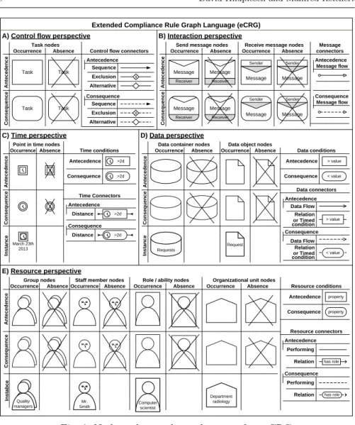
Basically, an extended Compliance Rule Graph (eCRG) comprises nodes andedges that may be further enriched withattachments. Nodes may be used to either expressevents (e.g., the start or completion of a task, the receipt of a message, or the occurrence of a particular point in time) or entities (e.g., a data object, staff member, or role). In turn, the edges of an eCRG describe the relations between the nodes. Examples of such relations include the or- der of events or hierarchical relations between the staff members. Moreover, conditions may be attached to refine event and entity nodes as well as the relations (i.e., edges between them). Examples of respective attachments in- clude restrictions on the data flow, the time distance between tasks, and the properties of staff members (e.g., a threshold for data flow values, maximum time distances, or required capabilities). Fig. 3 depicts the various kinds of nodes, edges and attachments supported by the eCRG language.
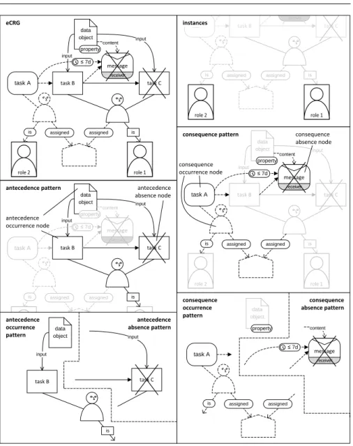
The specification of an eCRG comprises a pre- and a postcondition. The precondition specifies when the compliance rule shall be applied, whereas the postcondition needs to be met to satisfy the compliance rule. Accordingly, the elements of an eCRG (i.e., its nodes, edges and attachments) are partitioned into anantecedence pattern (A), which specifies the precondition, and at least oneconsequence pattern(C) specifying a postcondition. An eCRG may further contain references to instances of entities like a particular staff member (e.g.
Mr. Smith), data container (e.g.credit points), or point in time (e.g.26 October 2013). Note that certain instance nodes are neither part of the antecedence nor the consequence patterns as they are independent from both the pre- and postcondition of the eCRG.
Since the pre- and postconditions (i.e., the antecedence and consequence patterns) of an eCRG may require both the occurrence and the absence of certain events, the two patterns are further sub-divided into an occurrence sub-pattern on the one hand and an absence sub-pattern on the other. Note that elements of theantecedence occurrence (AO) and theconsequence occur- rence(CO) patterns require the occurrence of events, whereas elements of the antecedence absence(AA) and theconsequence absence (CA) patterns require certain events to not occur. To visually distinguish between the patterns, the eCRG language uses dashed lines and round shapes for the elements of a con- sequence pattern and, by contrast, solid lines and square shapes for the ones of an antecedence pattern. Thick lines and square shapes are used to represent elements referring to particular instances of entities. Absence nodes are crossed out by an oblique cross in order to to differentiate them from occurrence nodes.
Fig. 4 illustrates the partitioning of an eCRG into its antecedence and consequence patterns as well as corresponding sub-patterns.
Considering this partitioning of an eCRG, an execution log is compliant with an eCRG,iff for each match of the eCRG antecedence pattern (i.e., satis- faction of the precondition), at least one corresponding match of a consequence pattern of the eCRG can be found (i.e., satisfaction of the postcondition). If the log does not include any match of the antecedence pattern (i.e., violation
March 23th 2013
AntecedenceConsequence
Occurrence Absence
Task
Task Task
Extended Compliance Rule Graph Language (eCRG) A) Control flow perspective
Occurrence Absence Occurrence Absence
Sender
Receiver Message
Message
Sender Message
Sender
Receiver Message
Message
Sender Message Receiver
Message
Receive message nodes Send message nodes
AntecedenceConsequence
B) Interaction perspective
Sequence Exclusion Antecedence
Alternative Control flow connectors
Sequence Exclusion Consequence
Alternative X
X
Task
Receiver Message Task nodes
Data object nodes
AntecedenceConsequence
Requests
Request
Instance
D) Data perspective
< value
> value Data conditions
Data connectors
Data Flow Antecedence
Data Flow Consequence
Group nodes E) Resource perspective
AntecedenceConsequenceInstabce
Mr.
Smith Computer
scientist Quality
managers
Department radiology
property property Antecedence
Consequence Resource conditions
Resource connectors
Performing Relation Antecedence
has role
Relation Consequence
has role Absence
Occurrence Absence Occurrence Absence Occurrence Absence
Staff member nodes Role / ability nodes Organizational unit nodes Occurrence Absence Occurrence Absence
Data container nodes Occurrence Absence
Point in time nodes
Antecedence
Consequence
AntecedenceConsequenceInstance
Time conditions
>2d
>2d Antecedence
Consequence
Time Connectors
Distance Antecedence
Distance Consequence
>2d
>2d
Performing or Timed condition
or Timed condition
Occurrence C) Time perspective
Antecedence
Consequence connectors
Message
Message flow
Message flow
> value
< value Relation Relation
Fig. 3: Nodes, edges and attachments of an eCRG
of the precondition), the process log istrivial compliant. If there is a match of the antecedence pattern (i.e., satisfaction of the precondition), for which no corresponding match of a consequence pattern exists (i.e., violation of the postcondition), the execution logviolates the eCRG. Once compliance viola- tions are detected, proper actions can be triggered in order to compensate the rule violation or to at least ensure its reporting.
A match of a particular antecedence or consequence pattern requires suit- able events regarding the nodes of the occurrence sub-pattern. In addition, these events must satisfy all conditions imposed by the other elements of the pattern (i.e., edges, attachments, and entity nodes). For each absence node,
A Visual Language for Modeling Business Process Compliance Rules 9
task C
task B task A
receiver message
role 1 role 2
task C task B
is
role 1 assigned
input data
object input
task A
is
role 2
assigned
content
receiver message
task C task B
assigned input
data
object input
task A
is assigned
content
receiver message
is
task C task B
is
role 1 assigned
input data
object input
task A
is
role 2
assigned
content
receiver message antecedence pattern
consequence pattern consequence
absence node
consequence occurrence node antecedence
absence node
antecedence occurrence node
≤ 7d
≤ 7d
≤ 7d
task B input
data object
is
task C antecedence
occurrence pattern
antecedence
absence pattern content
receiver message
≤ 7d
assigned task A
is assigned
consequence occurrence pattern
consequence absence pattern property
data object property property
property
is
role 1 assigned
is
role 2
assigned
instances
input
eCRG
Fig. 4: Components of an eCRG
in turn, the corresponding events must be missing or not meet the conditions imposed by connected edges and attachments.
Note that the design of the eCRG language partially considers the prin- ciples for designing effective visual notations [73]. Especially, the concepts of semiotic clarity, perceptual discriminability, semantic transparency, graphic economy, and cognitive fit were taken into account.
3.2 eCRG Modeling
This section shows how the different process perspectives can be modeled with the eCRG language. For each perspective, we first introduce the corresponding eCRG elements before illustrating their semantics along simple examples.
3.2.1 Control Flow Perspective
A fundamental process perspective of
AntecedenceConsequence
Occurrence Absence
Task
Task Task
Control flow perspective
Sequence Exclusion Antecedence
Alternative Control flow connectors
Sequence Exclusion Consequence
Alternative X
X
Task Task nodes
Fig. 5: eCRG elements covering the control flow perspective compliance rules concerns the control flow,
which constrains the execution sequence as well as the occurrences of tasks. The elements of the eCRG language referring to the control flow perspective are shown in Fig. 5.
Task nodes express whether or not tasks of the given task type shall be ex- ecuted. In detail, four kinds oftask nodes are provided, which refer to theantecedence
occurrence,antecedence absence,consequence occurrence, andconsequence ab- sence pattern. Note that the specification of the task type may be omitted, if the latter is not relevant.
In addition to task nodes,antecedence andconsequence sequence flow con- nectors are provided. These connectors allow constraining the execution se- quence of tasks. The absence of sequence flow indicates a parallel flow; i.e., then any possible execution sequence is allowed for the respective tasks. To clearly distinguish betweenstart-start,start-end,end-start, andend-end con- straints in respect to the execution sequence of tasks, sequence flow connectors are either connected to the right or left border of a task node.Exclusive con- nections express that exactly one of the connected tasks must be executed. In turn, alternative connections express that at least one of the connected tasks shall occur. Exclusive as well as alternative connections may be part of both the antecedence and the consequence pattern, but they must solely connect nodes within a particular pattern. Exclusive as well as alternative connections may involve more than two nodes.
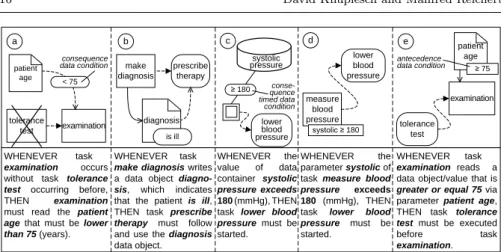
Fig. 6 provides basic examples of compliance rules referring to the con- trol flow perspective. The eCRG from Fig. 6a refers to compliance rule C6, whereas the eCRG from Fig. 6b models a variation of C1. Figs. 6c and 6d refer to the control flow perspective of C8 and C9 respectively. All eCRGs from Figs. 6a – 6c use one antecedence and one consequence occurrence task nodeas well as aconsequence sequence flow connector that connects both task nodes restricting their execution order. Fig. 6d shows anantecedence sequence flow connector specifying the order of twoantecedence occurrence task nodes, whereas twoconsequence sequence flow connectorslink theconsequence occur-
A Visual Language for Modeling Business Process Compliance Rules 11
rence task node placed between them.
order
X-ray
fill request
form perform
X-ray
perform surgery
b c d
WHENEVER task order X-ray occurs before task perform surgery, THEN task perform X- ray must occurre between tasks order X-ray and perform surgery.
WHENEVER task order X-ray occurs, THEN task fill request form must occur afterwards.
tolerance test
perform examination
WHENEVER task per- form examination oc- curs, THEN task toler- ance test must have occurred before.
inform
patient
request informed consent
WHENEVER task re- quest informed consent occurs, THEN task inform patient must have occurred before.
a antecedence occurrence
task node consequence occurrence
task node consequence
sequence flow
order X-ray
antecednece sequence flow
Fig. 6: Basic examples referring to the control flow perspective
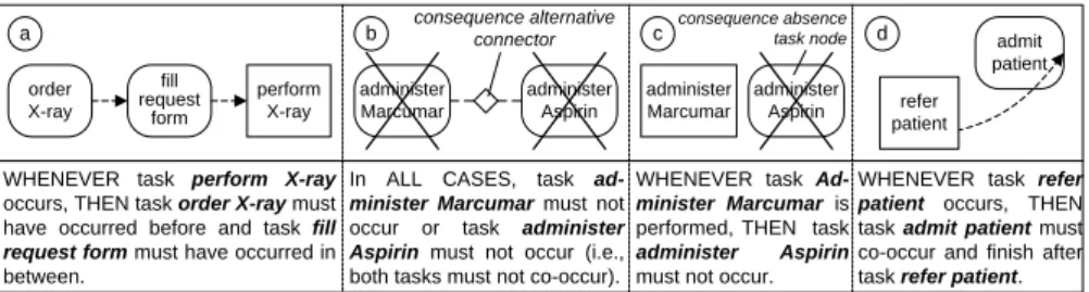
More sophisticated examples are depicted in Fig. 7. Fig. 7a uses twoconse- quence occurrence task nodesas well as aconsequence sequence flow connector to provide a more precise specification of compliance rule C1 (cf. Table 1). In order to capture the control flow perspective of C7, Fig. 7b provides twocon- sequence absence task nodes linked by a consequence alternative connection.
In turn, Fig. 7c solely uses anantecedence occurrence task node on the left and aconsequence absence task node on the right side (i.e., no connector is used).
Fig. 7d refers to compliance rule C4; note that its consequence sequence flow connector does not express an end-start constraint (as, for example, the rule in Fig. 7a), but anend-end constraint on the execution sequence of tasks.
order
X-ray fill request
form perform X-ray a
WHENEVER task perform X-ray occurs, THEN task order X-ray must have occurred before and task fill request form must have occurred in between.
administer Aspirin administer Marcumar
In ALL CASES, task ad- minister Marcumar must not occur or task administer Aspirin must not occur (i.e., both tasks must not co-occur).
WHENEVER task Ad- minister Marcumar is performed, THEN task administer Aspirin must not occur.
administer Aspirin administer
Marcumar
b c d
WHENEVER task refer patient occurs, THEN task admit patient must co-occur and finish after task refer patient.
admit patient refer
patient consequence alternative
connector
consequence absence task node
Fig. 7: Advanced examples referring to the control flow perspective
3.2.2 Interaction Perspective
The interaction perspective constrains the interactions a process may have with external partner processes, i.e., the exchange of messages with other or- ganizations and information systems. The eCRG language offers specific nodes for representing the events ofsending andreceiving messages.Sending andre- ceiving message nodesmay be part of theantecedence occurrence,antecedence
absence, consequence occurrence, or consequence absence patterns. As indi- cated in Fig. 8, labels on the message node not only allow specifying the message type, but also the message receiver and message sender respectively.
Similar to task nodes, the sender, receiver and message type label may be omitted.Antecedence andconsequence message flows connect message nodes referring to the sending and receipt of the same message.
Fig. 9 uses the elements from
Occurrence Absence Occurrence Absence
Sender
Receiver Message
Message
Sender
Message Sender
Receiver Message
Message
Sender
Message Receiver
Message
Receive message nodes Send message nodes
AntecedenceConsequence
Interaction perspective
Receiver Message
Antecedence
Consequence connectors
Message
Message flow
Message flow
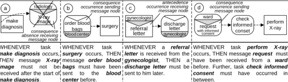
Fig. 8: eCRG elements covering the interaction perspective Fig. 8 to model compliance rules
referring to the interaction per- spective. In particular, Fig. 9a shows astart-startconstraint that uses theconsequence absencevari- ant of thereceiving message node to model the control flow and in- teraction perspectives of compli- ance rule C3 (cf. Table 1). Fig. 9b reflects C5 and includes aconse-
quence occurrence sending message. The combination of anantecedence occur- rence receiving messageas precondition and aconsequence occurrence sending message as postcondition is shown in Fig. 9c, whereas Fig. 9d depicts a con- sequence occurrence receiving message.
a b c d
WHENEVER task--- make diagnosis occurs, THEN message X-ray image must not be received after the start of make diagnosis.
WHENEVER task--- surgery occurs, THEN message order blood bags must have been sent to the blood center before.
WHENEVER task perform X-ray occurs, THEN message request must have been received from a ward before. Further, task check informed consent must have occurred in between.
WHENEVER a referral letter is received from the gynecologist, THEN a discharge letter must be sent to him later.
radiology X-ray
image check
informed conset
perform X-ray ward
gynecologist
referral letter surgery bloodcenter order blood
bags
gynecologist discharge
letter request with informed
consent antecedence occurrence receiving
message node consequence
occurrence sending message node
consequence absence receiving message node make
diagnosis
consequence occurrence sending
message node
Fig. 9: Examples referring to the interaction perspective
3.2.3 Time Perspective
When having a closer look on the informal definition of compliance rules C4 and C7 from Table 1, it becomes clear that Figs. 7b – 7d do not fully cover them yet. The time distance between the interactions and tasks of C4 is not considered by the eCRGs from Fig. 7d. The eCRGs from Figs. 7b+c completely disallow for the co-occurrence of the two tasks instead of solely defining the required minimum time distance between them.
A Visual Language for Modeling Business Process Compliance Rules 13
The time perspective of the eCRG language provides elements for cover- ing such kinds of constraints (cf. Fig. 10), i.e., for modeling points in time and time conditions. Similar to task and message nodes, antecedence occur- rence,antecedence absence, consequence occurrence, andconsequence absence point-in-time nodes are supported. Additionally,instance point-in-time nodes enable the specification of a concrete point in time (e.g., 26 October 2013).
Antecedence andconsequence time conditions may be attached to task nodes as well as sequence flow connectors to either constrain the duration of a task or the time distance between tasks/messages. Finally, antecedence and con- sequence time distance connectors may constrain the time distance between tasks/messages without implying a particular order between them.
Fig. 11 depicts examples of eCRGs con-
October 26th 2013 Occurrence Absence
Point in time nodes
AntecedenceConsequenceInstance
Time conditions
>2d
>2d Antecedence
Consequence
Time Connectors
Distance Antecedence
Distance Consequence
>2d
>2d
Time perspective
Fig. 10: eCRG elements cover- ing the time perspective sidering the time perspective as well. Fig. 11a
connects two antecedence occurrence task nodes using aconsequence time distance con- nector. This eCRG exactly corresponds to compliance rule C7 from Table 1. In turn, Fig. 11b enriches a consequence sequence flow connector with atime conditionto model compliance rule C4. To visually specify com- pliance rule C10, Fig. 11c uses an instance point-in-time node and attaches atime du- ration condition attachmentto an antecedence occurrence task node. The eCRG from Fig. 11d models compliance rule C5.
a b c d
administer Aspirin
WHENEVER both tasks administer Marcumar and ad- minister Aspirin occur, THEN the time distance between them must be greater than 5 days.
WHENEVER task refer patient occurs, THEN task admit patient must co-occur and be fin- ished within 7 days after the referral.
WHENEVER tasksurgery occurs, THEN message order blood bags must have been sent no later than 1 day before.
WHENEVER task tol- erance test is per- formed after October 26th, 2013, THEN it should be finished within 30 minutes.
administer Marcumar > 5d
tolerance test
≤ 30min surgery
≥ 1d
bloodcenter order blood
bags Oct 26th
2013 admit patient
≤ 7d refer patient consequence time distance connector
consequence time condition
instance point-in-time node
Fig. 11: Examples referring to the time perspective
3.2.4 Data Perspective
Fig. 12 depicts elements for modeling the data perspective of eCRGs:Data container nodes, data object nodes,data flow connectors, and data conditions are provided. Data containers refer to process data elements or global data
stores, whereasdata objects refer to specific data values and object instances respectively. Similar to point-in-time nodes, data container and data object nodes may be part of the antecedence occurrence, antecedence absence, con- sequence occurrence, or consequence absence patterns, whereas instance data nodes refer to specific data containers or data objects (e.g., data container current diagnosis or data objectX-ray image of Mr. Smith).
Antecedence andconse-
Data object nodes
AntecedenceConsequence
Requests
Request
Instance
Data perspective
< value
> value Data conditions
Data connectors
Data Flow Antecedence
Data Flow Consequence Occurrence Absence Occurrence Absence
Data container nodes
Antecedence
Consequence
or Timed condition
or Timed condition
> value
< value Relation Relation
Fig. 12: eCRG elements covering the data perspective
quence data flow connectors define which process tasks read from (write to) which data objects or data con- tainers. To enable the dis- tinction of different data flows, labels may refer to input/output parameters. The caption of a data object/container may specify the parameter name as well. Finally,antecedence and consequence data rela- tion connectors express re- lations among data objects.
To constrain values of data flow or parameters of tasks/messages, an- tecedence or consequence data conditions may be attached to data flow con- nectors and task/message nodes.Timed condition connectors may be added to the antecedence or consequence patterns to constrain the values of data containers at particular points in time.
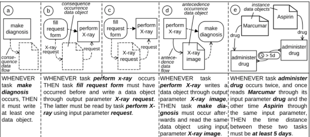
Fig. 13 provides examples of eCRGs withdata object nodes. Fig. 13a depicts an eCRG with a consequence occurrence data object and a consequence data flow connector. Figs. 13b+c depict a variant of compliance rule C1 (cf. Table 1) and highlight the specification of input/output parameters based on labeled
a
fill request
form b
perform X-ray
fill request
form
perform
X-ray make
diagnosis perform
X-ray
c d e
make diagnosis
WHENEVER task make diagnosis occurs, THEN it must write at least one data object.
WHENEVER task perform x-ray occurs THEN task fill request form must have occurred before and write a data object through output parameter X-ray request.
The latter must be read by task perform X- ray using input parameter request.
WHENEVER task --- perform X-ray writes a data object through output parameter X-ray image, THEN task make dia- gnosis must occur after- wards and read the same data object using input parameter X-ray image.
WHENEVER task administer drug occurs twice, and once reads Marcumar through its input parameter drug and the other time Aspirin through the same input parameter, THEN the time distance between these two tasks must be at least 5 days.
X-ray
request request request
X-ray request
X-ray image
administer administer drug
drug
> 5d Aspirin Marcumar drug drug consequence
occurrence data object
antecedence occurrence data object
instance data objects
conse- quence data flow
antece- dence data flow
Fig. 13: Examples referring to the data perspective using data objects
A Visual Language for Modeling Business Process Compliance Rules 15
a b c d e
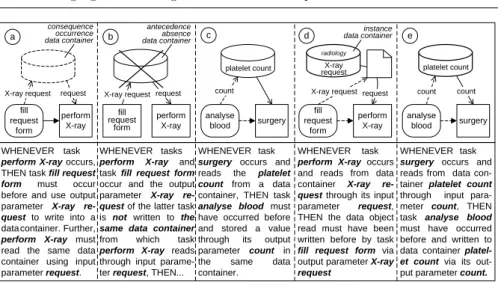
perform X-ray WHENEVER task--- perform X-ray occurs, THEN task fill request form must occur before and use output parameter X-ray re- quest to write into a datacontainer. Further, perform X-ray must read the same data container using input parameter request.
WHENEVER task--- perform X-ray occurs and reads from data container X-ray re- quest through its input parameter request, THEN the data object read must have been written before by task fill request form via output parameter X-ray request
WHENEVER task--- surgery occurs and reads the platelet count from a data container, THEN task analyse blood must have occurred before and stored a value through its output parameter count in the same data container.
WHENEVER task--- surgery occurs and reads from data con- tainer platelet count through input para- meter count, THEN task analyse blood must have occurred before and written to data container platel- et count via its out- put parameter count.
request fill
request form X-ray request
perform X-ray request requestfill
form X-ray request
surgery analyse
blood count
platelet count
perform X-ray request fill
request form
X-ray request
surgery count
analyse blood
count platelet count X-ray
request radiology
WHENEVER tasks---- perform X-ray and task fill request form occur and the output parameter X-ray re- quest of the latter task is not written to the same data container from which task perform X-ray reads through input parame- ter request, THEN...
consequence occurrence data container
antecedence absence data container
instance data container
Fig. 14: Examples referring to the data perspective using data containers
consequence occurrence data objectsandconsequence data flow connectors. An antecedence occurrence data object and the corresponding antecedence data flow are shown in Fig. 13d, whereas Fig. 13e uses twoparticular instances of data objects (i.e., Marcumar and Aspirin) to model compliance rule C7.
Fig. 14 illustrates the use ofdata container nodes. The eCRG from Fig. 14a uses aconsequence occurrence data container andconsequence data flow. The use of anantecedence absence data containeris illustrated by Fig. 14b, whereas the eCRG from Fig. 14c comprises anantecedence occurrence data container.
Figs. 14d+e refer toinstance data container nodes.
Fig. 15 provides examples illustrating the use of data condition attach- ments. In Fig. 15a, a consequence data condition constrains the value of a data flow, whereas theconsequence data condition in Fig. 15b refers to a data object. An antecedence timed data condition of a data container is depicted in Fig. 15c. Fig. 15d provides anantecedence data condition constraining the execution parameter of anantecedence occurrence task node. Finally, Fig. 15e attaches anantecedence data condition to a data object.
3.2.5 Resource Perspective
The resource perspective of the eCRG language covers various kinds of human resources as well as their relations. Furthermore, it allows constraining the assignment of resources to tasks (cf. Fig. 16).
The eCRG language covers various resources, includingstaff member,role, group, and organizational unit, as well as their relations with tasks. Similar to data nodes,resource nodes may be part of theantecedence occurrence,an- tecedence absence, consequence occurrence, and consequence absence pattern of an eCRG or refer to particular instances of resource entities (e.g., staff member Mrs. A or role physician). Performing relation connectors indicate the performers of tasks.Resource relation connectors express relations among