Universität Ulm| 89069 Ulm | Germany Fakultät für Ingenieurwissenschaften, Informatik und Psychologie
Institut für Datenbanken und Information- ssysteme
Enabling Multi-Perspective Business Process Compliance
Dissertation zur Erlangung des Doktorgrades Dr. rer. nat.
an der Fakultät für Ingenieurwissenschaften, Informatik und Psychologie der Universität Ulm
Vorgelegt von:
David Knuplesch geboren in Tübingen
2019
Prof. Dr. Stefanie Rinderle-Ma Tag der Promotion: 22.07.2019
Vorwort
Zwischen dem Tag, an dem der Entschluss für meine Dissertation fiel, und dem heutigen Tag, an dem ich dieses Vorwort schreibe, sind viele Jahre vergangen, auf die ich nun mit einer Mischung aus Wehmut und Erleichterung zurückblicke. Jetzt, wo das Ende dieses bisweilen faszinierenden und steinigen Weges erreicht ist, bleibt mir als letzter Schritt nur noch das Formulieren des Dankes an jene, die mich auf diesem Weg begleitet haben.
An erster Stelle danke ich meinem Doktorvater Prof. Dr. Manfred Reichert für die Möglichkeit zur Promotion und für seine stets umfangreichen Korrekturen, die in nicht unerheblichem Maße die Lesbarkeit und Verständlichkeit meiner Texte verbessert haben.
Im Anschluss daran danke ich Prof. Dr. Stefanie Rinderle-Ma und Dr. Walid Fdhila für die gemeinsame, publikationsreiche Zeit im C3Pro Projekt. Prof. Dr. Akhil Kumar danke ich für die stets angenehme Zusammenarbeit und seinen umsichtigen und konstruktiven Rat.
Ich danke all meinen Kolleginnen und Kollegen des Instituts für Datenbanken und Informationssysteme für die schönen Momente, die gemeinsamen Konferenzreisen und die interessanten Diskussionen. Besonders danke ich Dr. Linh Thao Ly, die mein Interesse am Themenkomplex Business Process Compliance weckte und mit deren Unterstützung meine ersten Publikationen entstanden. Dr. Andreas Lanz danke ich für die Latex- Vorlage und für seine hilfreichen Erfahrungswerte zur kumulativen Dissertation. Luisa Reinbold danke ich für die organisatorische Unterstützung in der kritischen Endphase meiner Dissertation.
Herzlich bedanken möchte ich mich bei Raphael Herfort, Franziska Semmelrodt, Hannes Beck und Manoubiya Zidi, welche im Rahmen ihrer Abschluss- und Projektarbeiten mit Prototypen, Fallstudien und empirische Untersuchungen die umfangreiche Validation meiner Forschung erst ermöglichten.
Zu Dank verpflichtet bin ich auch der Friedrich-Ebert-Stiftung für die finanzielle und ideelle Unterstützung, die sie mir in den ersten Jahren meiner Dissertation im Rahmen eines Stipendiums gewährte.
Mein größter Dank gilt aber meinen beiden Kinder Miên-Lia Mai und Ðan Erik Rei sowie meiner Frau.
Neu-Ulm, August 2019
Abstract
A particular challenge for any enterprise is to ensure that its business processes conform with compliance rules, i.e., semantic constraints on the multiple perspectives of the business processes. Compliance rules stem, for example, from legal regulations, corporate best practices, domain-specific guidelines, and industrial standards. In general, compliance rules are multi-perspective, i.e., they not only restrict the process behavior (i.e. control flow), but may refer to other process perspectives (e.g. time, data, and resources) and the interactions (i.e. message exchanges) of a business process with other processes as well.
The aim of this thesis is to improve the specification and verification of multi-perspective process compliance based on three contributions:
1. The extended Compliance Rule Graph (eCRG) language, which enables the visual modeling of multi-perspective compliance rules. Besides control flow, the latter may refer to the time, data, resource, and interaction perspectives of a business process.
2. A framework for multi-perspective monitoring of the compliance of running processes with a given set of eCRG compliance rules.
3. Techniques for verifying business process compliance with respect to the inter- action perspective. In particular, we consider compliance verification for cross- organizational business processes, for which solely incomplete process knowledge is available.
All contributions were thoroughly evaluated through proof-of-concept prototypes, case studies, empirical studies, and systematic comparisons with related works.
Kurzfassung
Eine wichtige Herausforderung für Unternehmen ist es, die Compliance ihrer Geschäfts- prozesse mit semantischen Constraints (sog. Compliance Regeln) sicherzustellen. Compli- ance Regeln leiten sich z.B. aus gesetzlichen Vorgaben, Best Practies, domänenspezifischen Richtlinien und Standards ab. Sie formulieren u.a. Bedingungen an die Ausführungsrei- henfolge von Arbeitsschritten., beziehen sich im Allgemeinen aber nicht nur auf die Kontrollflussperspektive, sondern auch auf andere Prozessperspektiven (z.B. Zeit, Daten und Resourcen) sowie die Interaktionen mit Partnerprozessen (d.h. den Austausch von Nachrichten).
Ziel der vorliegenden Arbeit ist die Unterstützung der Modellierung und Verifikation von Compliance Regeln unter Einbeziehung aller oben genannten Prozessperspektiven. Dazu werden drei wissenschaftliche Beiträge gemacht:
1. Dieextendend Compliance Rule Graph(eCRG) Sprache für die visuelle Modellierung von Compliance Regeln unter Einbeziehung von Verhalten (d.h. Kontrollfluss), Zeit, Daten, Ressourcen, ebenso wie auf den Nachrichtenflüssen mit Partnerprozessen.
2. Ein Rahmenwerk zur Überwachung von eCRG-basierten Compliance Regeln für laufende Geschäftsprozesse.
3. Techniken für die Verifikation von Compliance Regeln im Kontext unternehmenüber- greifender Prozesse, für welche lediglich eingeschränktes Wissen über die beteiligten Partnerprozesse vorliegt.
Die Beiträge dieser Arbeit werden mittels Proof-of-Concept Prototypen, Fallstudien, Empirischen Studien und systematischen Vergleich mit verwandten Arbeiten evaluiert.
Contents
1 Introduction 1
1.1 Motivation . . . 1
1.2 Scientific Contribution . . . 1
1.3 Outline of the Thesis . . . 3
2 Backgrounds 5 2.1 Business Processes . . . 5
2.1.1 Process Models . . . 6
2.1.2 Process Execution . . . 7
2.1.3 Process Change . . . 10
2.1.4 Processes Perspectives other than Control Flow . . . 12
2.2 Cross-Organizational Processes . . . 16
2.2.1 Collaboration Models . . . 16
2.2.2 Interaction Models . . . 19
2.2.3 Modeling Cross-organizational Processes . . . 19
2.3 Correctness Criteria for Business Process Models . . . 20
2.3.1 Structural Correctness . . . 20
2.3.2 Behavioral Correctness . . . 21
2.3.3 Verifying Cross-organizational Processes . . . 24
2.4 Business Process Compliance . . . 25
2.4.1 Modeling Compliance Rules . . . 26
2.4.2 A-priori Compliance Checking . . . 29
2.4.3 Run-time Compliance Monitoring . . . 30
2.4.4 A-Posteriori Compliance Checking . . . 31
2.4.5 Effects of Process Changes on Process Compliance . . . 32
3 Modeling Multi-Perspective Business Process Compliance Rules 33 3.1 Research Challenges . . . 33
3.2 Scientific Contribution . . . 35
3.3 Evaluation . . . 40
3.3.1 Pattern-based Evaluation . . . 41
3.3.2 Modeling Real-World Compliance Rules as eCRGs . . . 41
3.3.3 Experimental Evaluation . . . 42
3.3.4 Proof-of-Concept Prototype . . . 46
3.4 Related Work . . . 48
3.5 Summary . . . 52
4 Monitoring Multi-Perspective Business Process Compliance 53 4.1 Research Challenges . . . 53
4.2 Scientific Contribution . . . 56
4.3 Evaluation . . . 62
4.3.1 Evaluating eCRG Monitoring against CMFs . . . 63
4.3.2 Proof-of-Concept Prototype . . . 63
4.4 Related Work . . . 64
4.5 Summary . . . 66
5 Compliance Checking for Cross-Organizational, Adaptive Processes 67 5.1 Research Challenges . . . 67
5.2 Scientific Contribution . . . 69
5.2.1 Compliability . . . 70
5.2.2 Global Compliance . . . 71
5.2.3 Effects of Process Changes on Global Compliance . . . 72
5.3 Evaluation . . . 73
5.3.1 Proof-of-Concept Prototype . . . 73
5.3.2 Related Work . . . 74
5.4 Summary . . . 74 77 79 6 Summary and Outlook
Bibliography
Introduction 1
1.1 Motivation
Ensuring the correctness of its business processes constitutes a crucial task for any enterprise [Ly13, Aa18, FZ14]. Besides guaranteeing structural and dynamic soundness criteria, processes need to comply with semantic constraints, which we denote as compli- ance rules in this thesis. Corresponding rules can be derived from a variety of artifacts like, for example, legal regulations, corporate best practices, domain-specific guidelines, and industrial standards [GS09, Ly13, LR07]. In literature,compliance rules are often restricted to control flow constraints on a business process (i.e. to the occurrence and order of activities). In general, however, compliance rules may also refer to other process perspectives, including the time, resource, and data perspectives. In the context of cross-organizational business processes [FIRMR15], in addition, compliance rules may refer to interactions (i.e., message exchanges) between business partners.
As a prerequisite for ensuring business process compliance, a language for the formal and computer-readable specification of compliance rules is needed; in current practice, these rules are usually described informally. Formally specified compliance rules, can then be taken as input for automated compliance checking. However, depending on whether compliance shall be checked at design or run time and on the kind of process (i.e., intra- vs. cross-organizational), different process information is available. Consequently, several compliance checking techniques are required to validate business process compliance for the various scenarios.
1.2 Scientific Contribution
This cumulative thesis provides three contributions that shall enable the specification, monitoring and verification of multi-perspective business process compliance.
The first contribution focuses on the visual specification of multi-perspective compliance rules. For this purpose, [KRL+13b, KR17] introduce the visual extended Compliance Rule Graph (eCRG) language, which enables the visual modeling and verification of compliance rules that may refer to the control flow, resource, data, time, and interaction
perspectives of a business process. In particular, eCRGs rely on a formal semantics specified in terms of first-order logic. To evaluate eCRGs several steps are taken: First, a proof-of-concept prototype is implemented, enabling the modeling of eCRGs as well as their verification against the event logs of completed process instances. Second, case studies, empirical studies, and a systematic comparison with related works shall demonstrate the applicability and usefulness of the eCRG language.
The second part of the thesis introduces a framework for the online monitoring (i.e., compliance checking) of eCRG compliance rules during process execution [KRK15b, KRK17]. For this purpose, the events produced by running processes are observed. In response to these events, the elements of an eCRG are marked step-by-step with text labels, colors and symbols in order to highlight the respective state of the compliance rule. In particular, the eCRG monitoring framework meets all compliance monitoring functionalities (CMF), which are considered as relevant in [LMM+15]. For example, the framework is able to continuously and reactively monitor multiple instances of the same eCRG. In addition, the eCRG monitoring framework provides compliance metrics and supports root-cause analyses at the occurrence of compliance rule violations. The eCRG monitoring framework is evaluated through a proof-of-concept implementation, which is applied to different use cases. Finally, the prototype is subject to performance
Table 1.1: Contributions
Scientific contribution Evaluation Publications Modeling process compliance rules
●expressive visual notation for modeling com- pliance rules;
●support of multiple process perspectives, i.e., control flow, data, time, resources, and inter- action;
●formal specification.
●proof-of-concept prototype
●case study
●pattern-based evaluation
●empirical studies
[KRL+13b]
[KR17]
Framework for monitoring business process compliance
●support of multiple process perspectives, i.e., control flow, data, time, resources, and inter- action;
●enables continuous monitoring of multiple compliance rule instantiations;
●visual feedback for users.
●proof-of-concept Prototype
●performance measurements
●evaluation against CMF
[KRK15a]
[KRK15b]
[KRK17]
Checking the compliance of cross- organizational processes
●compliance criteria for cross-organizational processes
● support of privacy and not-yet-specified behavior
●estimates the effects of changes on compli- ance
●proof-of-concept Prototype [KRM+13]
[KRFRM13]
[KRP+13]
[KFRRM15]
1.3 Outline of the Thesis
measurements.
The third part of the thesis introduces compliance checking techniques for cross-organizational business processes. Thereby, the particular challenge is to cope with incomplete process information. [KRFRM13, KRP+13] introduce compliance criteria for cross-organizational processes as well as corresponding techniques for verifying compliance in this context.
Finally, [KFRRM15] limits the number of compliance rules to be rechecked after changing a cross-organizational business process. A sophisticated proof-of-concept implementation evaluates the presented contributions.
Table 1.1 summarizes the contributions of this thesis.
1.3 Outline of the Thesis
The cumulative thesis is structured as follows: Chapter 2 introduces fundamental con- cepts and notions needed for understanding the thesis. Chapter 3 then presents the extended Compliance Rule Graph (eCRG) language, which enables the modeling of multi- perspective compliance rules. The framework for visually monitoring multi-perspective compliance rules during process execution (i.e. at run time) is presented in Chapter 4.
Chapter 5 introduces the approach for verifying the compliance of cross-organizational business processes at design time. Finally, Chapter 6 provides a summary and an outlook.
All publications related to the cumulative thesis are contained in the appendices.
Backgrounds 2
This chapter introduces fundamental concepts and basic terminology needed for under- standing this thesis.
2.1 Business Processes
According to [Wes12], a business process is a set of activities that are performed in order to achieve a certain and recurring business goal, e.g., the processing of an order or the treatment of a patient [DRMR18, LR07]. A process model, in turn, describes the execution constraints for the activities of a business process.
Example 2.1 (Business process)
A simple example of a process from the healthcare domain is depicted in Fig. 2.1. It outlines an outpatient treatment that comprises five activities. The process starts with the admission of the patient. Then, the latter is examined and a diagnosis is made.
Finally, medicine is prescribed and the patient is discharged.
admit
patient examine
patient prescribe
medicine
diagnosismake discharge
patient
Figure 2.1: Patient treatment process
The life cycle of a business processes comprises four phases [WRRM08]:
• In the modeling phase (i.e.,design time), a (visual) process model is specified.
• In theexecution phase (i.e., run time), instances of thebusiness processes model are created and then executed according to the logic prescribed by this process model. To allow for a comprehensive analysis of running processes, process logs record all events occurring during the execution of the process instances.
• The change phase deals with instance-specific changes, which are recorded in change logs.
• The analysis phase refers to the a-posteriori analysis of process logs created during the execution of process instances. The result of this phase, in turn, might trigger changes of the process model.
The four phases may overlap if multiple instances of the same process are considered.
While some process instances are still running, business analysts may already investigate the logs of completed process instances of the same model. Likewise, changes may be applied to a model, while corresponding process instances are still running [RRD04].
2.1.1 Process Models
According to [Wes12], a process model describes the execution constraints between the activities of a business process. In this thesis,process models are considered to be directed graphs that are composed of different kinds of nodes and edges. In particular, the Business Process Model and Notation 2.0 (BPMN 2.0) standard [OMG14] is applied.
Besides thestart and end nodes of a process, the most basic nodes of a BPMN process model refer to process activities. The edges linking the activity nodes are denoted as sequence flow (edges) and define the order between the activities. In turn,gateways are special nodes that allow splitting and merging sequence flows in order to realize alternative or parallel execution branches. For example, if anAND-split gateway is reached, each of its outgoing sequence flows becomes enabled, whereas anXOR-split gateways enforces the selection of exactly one of the outgoing flows. Accordingly, AND-join gateways correspond to synchronization points that wait for all incoming sequence flows, whereas XOR-join gateways wait for exactly one of the incoming sequence flow edges, before processing with control flow. All these elements form thecontrol flow perspective of a process model.
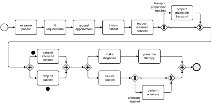
Example 2.2 demonstrates the use of these elements along the process of an X-ray examination for an inpatient in a hospital [KSR96b, Sem13].
Example 2.2 (X-ray examination process for inpatients)
The process starts with a physical examination of the inpatient by a ward physician who then orders an X-ray examination. For this purpose, a corresponding form has to be filled, which collects information about the examination as well as required preparations and aftercare. The order form is then forwarded to the Radiology Department, which schedules an appointment for the X-ray examination.
Before the examination, the ward physician informs the patient about the risks of the X-ray examination and asks for her informed consent. If required, a nurse prepares the inpatient before transporting her to the Radiology Department at the time of the examination. However, this transport must not be started unless the secretary of the Radiology Department asks for the inpatient. While the patient is dropped off, the signed informed consent is sent to the Radiology Department.
2.1 Business Processes
The Radiology Department informs the ward as soon as the X-ray examination is completed. Following this, a nurse from the ward picks up the patient, bringing her back to the ward. If required, aftercare is provided by the nurse. At some time, the Radiology Department sends the digital X-ray images. Finally, the ward physician uses this images to make a diagnosis, prescribes a therapy for the inpatient, and documents the therapy.
Fig. 2.2 depicts the process model introduced by Example 2.2. Note that there exist other expressive process model languages, like ADEPT2 [RRKD05, DR09] or YAWL [AH05], which enable the visual modeling of business processes as well.
examine
patient fill
request form inform
patient
drop off patient
request informed consent request
appointment
transport preparation
required prepare patient for transport
transmit informed consent
pick up patient make
diagnosis prescribe
therapy
aftercare required
perform aftercare activity
nodes start node
end node sequence flow edges
XOR-split gateway
XOR-join gateway
AND-split
gateway AND-join
gateway
Figure 2.2: X-ray examination process expressed as BPMN 2.0 model
2.1.2 Process Execution
In general,process models should be based on a well-defined operational semantics that enables their proper simulation and execution. Thus, process models are transformed into a stateful representation that allows determining the current process state as well as the set of valid actions (e.g. start or completion of an activity) that may be applied in this state. Furthermore, for each of these actions the state resulting afterwards must be clear. A stateful representation of a process model can be achieved, for example, through its translation into a stateful representation using another formalism, e.g., Petri-nets, or by annotating process elements with tokens.
Process Instances
Aprocess instance represents a concrete case of a business process [Wes12]. In particular, a process instancereflects a particular state of the corresponding process model.
Example 2.3 (Token-based process execution)
Fig. 2.3 shows an instance of the X-ray examination process as depicted in Fig. 2.2 (cf. Example 2.2). Thereby, the instance state is indicated through tokens. Re- garding the depicted instance, activities examine patient, fill request form, request appointment, inform patient, and request informed consent are com- pleted, whereas activity drop off patient is running and activity transmit informed consent may still be started.
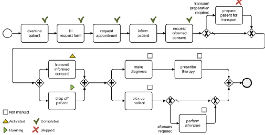
Example 2.4 (Marking-based process execution)
Fig. 2.4 shows the process instance using the ADEPT2 formalism [RRKD05, Rei00].
Markings are used to indicate the current state of the process instance. Thereby, activities are either marked as activated, running,completed,skipped, or not active to highlight the current state as well as possible actions. For example, activities examine patient and fill request form were already executed, whereas activity prepare patient for transport was skipped, i.e., the other branch of the preceding XOR-split gateway was chosen (cf. Section 2.1.1). Finally, activities drop off patient and transmit informed consent are marked as running and activated, respectively.
examine
patient fill
request form inform
patient
drop off patient
request informed consent request
appointment
transport preparation
required prepare patient for transport
transmit informed consent
pick up patient make
diagnosis prescribe
therapy
aftercare required
perform aftercare
Figure 2.3: Token-based instance of the X-ray examination process
Process logs and traces
Process logs recordactivities andevents that have occurred during the execution of the respective process instance.
A fundamental kind of process log is provided byactivity logs, which record the sequence in which the activities of a process instance were started and completed respectively.
Table 2.1 shows a possible activity log of the X-ray examination process introduced in Example 2.2.
2.1 Business Processes
Not marked Activated Completed
Skipped Running
examine
patient fill
request form inform
patient
drop off patient
request informed consent request
appointment
transport preparation
required prepare patient for transport
transmit informed consent
pick up patient make
diagnosis prescribe
therapy
aftercare required
perform aftercare
Figure 2.4: Instance of the X-ray examination process in ADEPT2
Activity logs (cf. Table 2.1) contain exactly one atomic entry for each activity instance and, hence, cannot describe concurrent executions of activities without additional information.
In turn, event logs (i.e., another kind of process logs) allow distinguishing between different events referring to the same instance of an activity. Event logs contain at least the events referring to the start and end of the executed activities. Entries of an event log need additional attributes to denote the type of the respective event (e.g., start event) and to relate the events referring to the same activity instance.
Example 2.5 (Process log)
Table 2.2 shows an example of an event log of the X-ray examination process (cf.
Example 2.2). It refers to the same process instance as the activity log from Table 2.1.
However, Entries 13-16 highlight that activities drop off patient and transmit informed consent are concurrently executed, whereas this does not become clear from the activity log depicted in Table 2.1.
Table 2.1: Activity log of the X-ray examination process (cf. Example 2.2)
# activity
1 examine patient 2 fill request form 3 request appointment
4 inform patient
5 request informed consent 6 prepare patient for transport 7 drop off patient 8 transmit informed consent 9 pick up patient 10 perform aftercare 11 make diagnosis 12 prescribe therapy
Table 2.2: Event log of the X-ray examination process (cf. Example 2.2)
# type id activity
1 start 1 examine patient
2 end 1 examine patient
3 start 2 fill request form
4 end 2 fill request form
5 start 3 request appointment 6 end 3 request appointment
7 start 4 inform patient
8 end 4 inform patient
9 start 5 request informed consent 10 end 5 request informed consent 11 start 6 prepare patient for transport 12 end 6 prepare patient for transport 13 start 6 drop off patient 14 start 7 transmit informed consent 15 end 7 transmit informed consent
16 end 6 drop off patient
17 start 8 pick up patient
18 end 8 pick up patient
19 start 9 perform aftercare 20 end 9 perform aftercare 21 start 10 make diagnosis
22 end 10 make diagnosis
23 start 11 prescribe therapy 24 end 11 prescribe therapy
To distinguish between logs of still running and logs of already completed process instances, the former are denoted aspartial logs, whereas the latter are summarized under the term completed log. Note that, in general, process logs refer to real process instances. In turn,
a process trace refers to a theoretically possible execution of a process model. Again, partial and completed traces need to be distinguished.
Completed tracescorrespond to theoretically possible executions that reached a final state and, hence, will not be continued, i.e., no activity is running and no activity can be started anymore. In turn,partial tracesmay refer to intermediate states and be continued through the completion of still running activities or the start of not yet enabled ones.
The activity log from Table 2.1 and the event log from Table 2.2 present examples of a completed logs of the X-ray examination process (cf. Example 2.2). In turn, Table 2.3 shows a partial event log reflecting the state of the process instance depicted in Fig. 2.3.
2.1.3 Process Change
The ability to adapt its business process is crucial for any enterprise to cope with environmental changes and exceptional situations [WSR09, RRMD09, RW12, LR16].
2.1 Business Processes
Table 2.3: Partial event log of the X-ray examination process (cf. Example 2.2)
# type id activity
1 start 1 examine patient 2 end 1 examine patient 3 start 2 fill request form 4 end 2 fill request form 5 start 3 request appointment 6 end 3 request appointment 7 start 4 inform patient
8 end 4 inform patient
9 start 5 request informed consent 10 end 5 request informed consent 11 start 7 drop off patient
Formally, aprocess change can be considered as a transformation of a process modelM into a process model M′.
Basic process model changes include the insertion and deletion of activities [WRRM08].
Based on these changes, more complex changes may be composed, e.g., moving of an activity within a process model can be realized by first removing the activity and then re-inserting it at another position [WPTR13].
Similar to process logs, which record the activities performed during the execution of a process instance, change logs record the basic changes that compose a complex process changes [GRRA06, RJR07]. Change profiles, in turn, provide a more condensed view on changes as they only outline which activities were added or removed.
Example 2.6 (Process change)
A change of the X-ray examination process (cf. Example 2.2) is illustrated in Fig. 2.5.
In particular, activity make diagnosis should be postponed until the patient returns from the radiology. Furthermore, the room of the patient should be cleaned during her absence. Table 2.4 shows the corresponding change log, the change profile is depicted in Table 2.5
Table 2.5: Change profile of the X-ray examination process (cf. Example 2.6)
# activity change Legend:
1 clean room + +add activity
2 make diagnosis ± −remove activity
3 prescribe therapy ± ±add and remove activity
examine
patient fill
request form inform
patient
drop off patient
request informed consent request
appointment
transport preparation
required prepare patient for transport
transmit informed consent
pick up patient make
diagnosis prescribe
therapy
aftercare required
perform
aftercare make
diagnosis prescribe
therapy clean
room
Figure 2.5: A change of the X-ray examination process (cf. Example 2.6) Table 2.4: Change log of the X-ray examination process (cf. Example 2.6)
# type activity position
1 add clean room after: transmit informed consent, drop off patient before: make diagnosis, pick up patient
2 remove make diagnosis 3 remove prescribe therapy
4 add make diagnosis after: pick up patient, perform aftercare 5 add prescribe therapy after: make diagnosis
2.1.4 Processes Perspectives other than Control Flow
Obviously, the control flow perspective is not sufficient to specify all aspects of a business process. For example, the process model from Fig. 2.2 neither specifies whether the two activities request informed consent and transmit informed consent refer to the same informed consent nor does the model state that a ward physician shall examine the patient. Finally, Fig. 2.2 does not define the point in time, at which the patient needs to be prepared for the transport. Corresponding aspects are covered by the following process perspectives:
• Resource perspective. This perspective specifies the (human) resources that shall execute the various process activities. In general, an activity is not directly assigned to a specific resource, but rather to a resource class based on capabilities, roles, affiliations, or historic process information [RAHE05, CRC11, CKR+15].
• Time perspective. This perspective specifies when activities shall be executed and which temporal constraints need to be obeyed. It includes, for example, constraints on time distances between activities or deadlines for activity execution [LWR14, LRW16].
2.1 Business Processes
• Data perspective. This perspective refers to thedata objects created, exchanged and processed by activities during the execution of a process instance [Rei12, KPR12a].
• Interaction perspective. This perspective defines the interactions a business process has with its partner processes. In general, the interactions refer to the exchange of messages with partners [BDH05, FIRMR15].
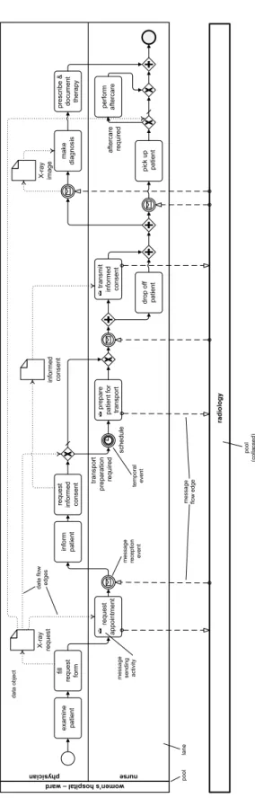
In order to cover these additional perspectives, process models need to be enriched accordingly. For example, BPMN 2.0 allows modeling the resource perspective with pools andlanes. Pools group the activities according to their affiliation, whereas lanes group activities of a particular partner based on roles, positions or capabilities. In turn, temporal events enable the modeling of deadlines or delays, whereas the data flow can be expressed withdata objects anddata flow edges [RD98, Rei00]. Moreover, the exchange of information between partner processes can be expressed through specific activities (or events) sending or receiving messages. Finally, a message flow edge connects the sender of a message with its receiver.
Fig. 2.6 depicts the X-ray examination process for inpatients covering all mentioned perspectives.
To properly support the latter, a process log not only needs to record the events referring to the start/end of activities, but additional information on the resource, time, data, and interaction perspectives.
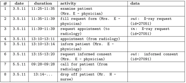
Example 2.7 (Multi-perspective activity and event logs)
Table 2.6 enriches the partial event log depicted in Table 2.3 with additional information covering the resource, time, data, and interaction perspectives. First, the point in time of an event occurred is captured. Second, each human activity is annotated with the human actor (i.e. resource) processing it. As opposed to the event log from Table 2.3, the event log from Table 2.6 contains additional events related to the sending/receipt of messages (e.g., Events 6-8 and 16-17) or describing how data objects are processed (e.g., Events 4 and 7). A partial activity log of the same process instance is depicted in Table 2.7. Note that its entries are enriched with timestamps related to the start and completion of activities. In addition, the involved resources and data objects are listed.
radiology
wom en’s hospita l – w
ard physician nurse
examine patientfill request forminform patient drop off patient request informed consent request appointment schedule
transport preparation required prepare patient for transport transmit informed consent pick up patient make diagnosisprescribe & document thera
py
aftercare req
uired
perform aftercare
X-ray requestinformed consent
X-ray image message flow edgetemporal event
data flow edges
data object pool (collapsed)
pool lane
message reception event
message sending activity
Figure 2.6: Process model covering the control flow, resource, time, data, and interaction perspectives (cf. Example 2.2)
2.1 Business Processes
Table 2.6: Event log of the X-ray examination process instance (cf. Fig. 2.2) covering the control flow, resource, time, data, and interaction perspectives.
# date time type id activity / data
1 3.5.11 11:25 start 1 examine patient (Mrs. E - physician)
2 3.5.11 11:35 end 1 examine patient
3 3.5.11 11:35 start 2 fill request form (Mrs. E - physician) 4 3.5.11 11:38 write 2 X-ray request (id=27051)
5 3.5.11 11:39 end 2 fill request form
6 3.5.11 11:39 send 3 request appointment (to radiology) 7 3.5.11 11:39 read 3 X-ray request (id=27051)
8 3.5.11 11:39 end 3 request appointment
9 3.5.11 13:10 receive 4 appointment (from radiology)
10 3.5.11 13:11 end 4 appointment
11 3.5.11 13:10 start 5 inform patient (Mrs. E - physician)
12 3.5.11 13:14 end 5 inform patient
13 3.5.11 13:15 start 6 request informed consent (Mrs. E - physician) 14 3.5.11 13:19 write 6 informed consent (id=27091)
15 3.5.11 13:20 end 6 request informed consent 16 5.5.11 09:28 receive 7 call for patient (from radiology)
17 5.5.11 09:28 end 7 call for patient
18 3.5.11 13:14 start 7 drop off patient (Mr. H - nurse)
Table 2.7: Activity log of the X-ray examination process instance (cf. Fig. 2.2) covering the control flow, resource, time, data, and interaction perspectives.
# date duration activity data
1 3.5.11 11:25–11:35 examine patient (Mrs. E - physician)
2 3.5.11 11:35–11:39 fill request form (Mrs. E - physician)
out: X-ray request (id=27051)
3 3.5.11 11:39–11:39 request appointment (to radiology)
in: X-ray request (id=27051)
4 3.5.11 13:10–13:11 appointment (from radiology) 5 3.5.11 13:10–13:14 inform patient (Mrs. E -
physician)
6 3.5.11 13:15–13:20 request informed consent (Mrs. E - physician)
out: informed consent (id=27091)
7 5.5.11 09:28–09:28 call for patient (from radiology)
8 3.5.11 13:14–... drop off patient (Mr. H - nurse)
2.2 Cross-Organizational Processes
Usually, the manufacturing of complex products and the provision of sophisticated services require the collaboration of multiple enterprises or organizational units [MHHR06]. In particular, the enactment of business processes is not necessarily restricted to one enterprise, but may cross organizational borders, i.e., it may involve multiple autonomous partners collaborating with each other to achieve of a common business goal [FIRMR15].
Note that this applies to the healthcare scenario from Example 2.2 as well. In turn, Example 2.8 provides the view of the Radiology Department on the overall process.
Example 2.8 (X-ray examination process for inpatients)
From the viewpoint of the Radiology Department, the process starts with the receipt of an X-ray request form of the Women’s Hospital. Then, the secretary schedules the examination and informs the Women’s Hospital accordingly.
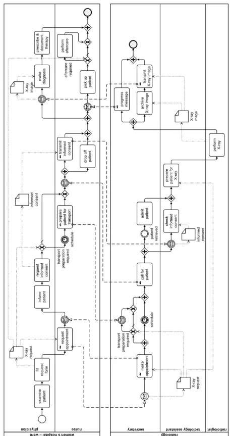
When the appointment approaches, the secretary notifies the Women’s Hospital. As described in Example 2.2, the Women’s Hospital sends the patient and signed informed consent. When the patient arrives at the Radiology Department, she is admitted by the secretary. The informed consent, in turn, is checked by a radiology assistant. Subsequently, the assistant prepares the patient for the X-ray examination, which is then performed by a radiologist. Afterwards the Women’s Hospital is informed about the completion of the examination by the secretary, who archives the created X-ray images before transmitting a digital copy to the Women’s Hospital.
Fig. 2.7 shows the inpatient X-ray examination process from the viewpoint of both the Women’s Hospital and the Radiology Department (cf. Examples 2.2 and 2.8).
2.2.1 Collaboration Models
The synthesis of the process models of collaborating partners results in acollaboration model. Fig. 2.7 depicts such a collaboration model that comprising the processes of the two partners involved in the X-ray examination process. In general, collaborating partners solely provide public models (i.e., views) of their processes, which hide private aspects from the public.
Example 2.9 (Collaboration model)
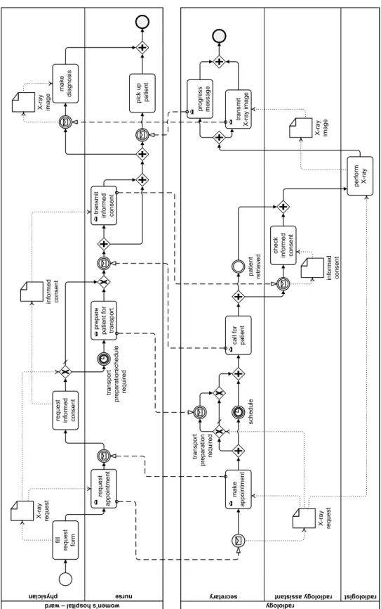
Fig. 2.7 shows the public models of the inpatient X-ray examination process for both the Women’s Hospital and the Radiology Department. As opposed to the collaboration model depicted in Fig. 2.7, the public model of the Women’s Hospital abstracts from ac- tivities examination, inform patient, drop off patient, prescribe & document therapy, and perform aftercare.
2.2 Cross-Organizational Processes
nurse or nursin
g assistant
radiol
ogy ogy assistant radiol ogist radiol
secreta
wom ry
en’s hospita l – w
ard physician nurse
examine patientfill request forminform patient drop off patient
request informed consent check informed consent
request appointment schedule transport preparation required
prepare patient for transport transmit informed consent pick up patient make diagnosisprescribe & document thera
py
aftercare req
uired
perform aftercare make appointment schedule
transport preparation required call for patientadmit patient prepare patient for X-ray perform X-ray transmit X-ray imagepatient retrieved
progress message
X-ray request X-ray request
informed consent informed consent
X-ray image
X-ray image archive X-ray image
Figure 2.7: Collaboration model of the X-ray examination process
nurse or nursin
g assistant
radiol
ogy ogy assistant radiol ogist radiol
secreta wom ry
en’s hospita l – w
ard physician nurse
fill request form
request informed consent check informed consent
request appointment scheduletransport preparation required prepare patient for transport transmit informed consent pick up patient
make diagnosis make appointment schedule
transport preparation required call for patient perform X-ray transmit X-ray image patient retrieved
progress message
X-ray request X-ray request
informed consent informed consent
X-ray image X-ray image
Figure 2.8: Collaboration model showing the public models of the X-ray examination process
2.2 Cross-Organizational Processes
2.2.2 Interaction Models
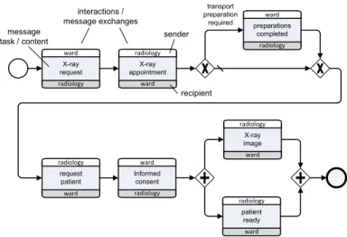
Interaction models provide an abstract view on cross-organizational business processes.
In particular, an interaction model abstracts from activities focusing on the messages exchanged instead. Moreover, interaction models specify the control flow for coordinating the interactions between partners through the exchange of messages.
X-ray
request X-ray
appointment
request patient ward
ward
ward radiology
radiology
radiology
Informed consent
preparations completed
ward
radiology transport
preparation required
X-ray image ward radiology
patient ready
ward radiology ward
radiology interactions / message exchanges
sender
recipient message
task / content
Figure 2.9: Interaction model for the X-ray examination process
2.2.3 Modeling Cross-organizational Processes
Cross-organizational processes may be specified as a meta-process, which starts with the collaborative specification of the interaction model. Then, the partners describe their public models and, finally, they specify and implement their private ones. All partners must agree on the interaction model and all public models are shared among the partners and approved by them. In turn, private models are specified by each partner autonomously (cf. Fig. 2.10).
Specify
interaction model Specify public
process model Specify private
process model
Figure 2.10: Meta process of modeling cross-organizational processes
2.3 Correctness Criteria for Business Process Models
Like other kinds of dynamic models, business process models are subject to correctness criteria. The latter can be assigned to three different layers, which build on each other as illustrated in Fig. 2.11.
Structural Correctness Behavioral Correctness Semantic Correctness
Business Process Compliance
Soundness
Correct Syntax
Figure 2.11: Layers of process model correctness [KRM+13]
2.3.1 Structural Correctness
The first fundamental layer of process model correctness refers to structural model correctness. A process model is considered as being structurally correct if it does not violate the syntax rules of the process meta model used for its description. Amongst others, this means that the various model elements are used according to the rules of the meta model. For example, start nodes must not have any incoming sequence flows and end nodes must not have any outgoing sequence flows. Structural correctness can be easily verified by checking the existence or absence of required and forbidden relations.
Note that the structural correctness of a process model constitutes a prerequisite for its execution.
Example 2.10 (Structural Correctness)
Fig. 2.12 shows a process model that contains a structural error. In particular, the end event is followed by activity B, i.e., the end event has an illegal outgoing sequence flow edge. In addition, activity B requires an outgoing sequence flow, which is missing.
A B
Figure 2.12: Structurally incorrect process model
2.3 Correctness Criteria for Business Process Models
For cross-organizational business processes, structural correctness additionally necessitates structural compatibility [DW07]. The latter, in turn, requires from the processes of a collaboration to use the same messages, i.e., if the process of a partner sends a certain message, the process of the partner receiving the message must comprise a corresponding receipt event and vice versa.
Example 2.11 (Structural Compatibility)
Fig. 2.13 shows two process models which are not structurally compatible. The upper process model sends message M1, while the lower model is waiting solely for message M2.
A M1
M3
M4 M2
Figure 2.13: Structurally incompatible process models
2.3.2 Behavioral Correctness
In [RW12],process model soundness(i.e., behavioral correctness) refers to the three basic correctness criteria option to complete, proper completion, andabsence of dead activities.
A process model has theoption to complete if each running instance, not being in a final state yet, can still be completed, i.e., neither deadlocks nor livelockshave occurred. In addition, once a final state is reached, there must be no activity in state running or enabled, i.e. the process completes properly. Finally, each activity is part of any valid possible execution of the process model, i.e. there areno dead activities.
Example 2.12 (Deadlock)
An example of a process model with a deadlock is provided by Fig. 2.14. No instances of the depicted process model can complete. Note that the AND-join gateway waits for both incoming sequence flows, whereas the preceding XOR-split gateway only triggers one of the two sequence flows.
Example 2.13 (Livelock)
Fig. 2.15 shows an example of a process model with a livelock. If theXOR-split gateway selects the upper sequence flow, the process will never exit the loop block containing activity B.
Example 2.14 (Proper completion)
Fig. 2.16 shows a process model whose instances will not properly complete as they may reach the end node even though there may be remaining tokens. In detail, when reaching theAND-split gateway, both B and C become enabled. As soon as one of the two activities completes, the end node is reached, even though the other activity is still enabled or running.
Example 2.15 (Dead activities)
The problem ofdead activities is illustrated by Fig. 2.17. In this process model, there exists no possible execution path that includes activity B.
A
B
C
Figure 2.14: Process model with dead- lock
A
B
C
Figure 2.15: Process model with poten- tial livelock
A
B
C
Figure 2.16: Process model with in- proper completion
A
B
C
Figure 2.17: Process model with dead activity
Regarding cross-organizational processes, additional criteria need to be met in order to ensure soundness of the overall process.
First,behavioral compatibility between the process models of a process collaboration shall ensure that the collaboration is sound again [AW01, DW07].
Example 2.16 (Behavioral Compatibility)
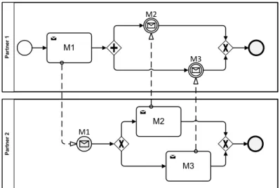
Fig. 2.18 shows an example of two incompatible process models. Though the individ- ual process models of the two partners are structurally compatible and sound, their
2.3 Correctness Criteria for Business Process Models
combination results in a deadlock, i.e., the collaborative process is not sound. After Partner 1 sends message M1, either message M2 or M3 is sent byPartner 2. However, the process of Partner 1 cannot complete as it waits for both messages M2 and M3 , i.e., the collaboration ends in a deadlock.
Partner 1Partner 2
M2
M3 M2
M1
M1
M3
Figure 2.18: Behaviorally incompatible process models
Theconformance of a public or private process model with an interaction model ensures that the process implements the behavior of a certain partner as required by the interaction model. Accordingly, conformance of a private process with the corresponding public process ensures that the private model implements the behavior of the public model [DW07].
Example 2.17 (Conformance)
In Fig. 2.19, neither the public process model (cf. Fig. 2.19b) conforms to the interaction model (cf. Fig. 2.19a), nor does the private process model (cf. Fig. 2.19c) conform to the public process model or the interaction model. In particular, the interaction model requires from Partner 2 to send M2 and M3 after receiving M1. In turn, the public and private models of Partner 2 either send message M2 or M3. Furthermore, the public model of Partner 2 requires the execution of activity A after sending message M2. However, the private model executes activity Q instead of activity A.
Realizability shall ensure that an interaction model can be realized by a collaboration of partner processes, i.e., there exists a collaboration of partner process models, which interact exactly as described by the interaction model.
(a) Interaction model
M1 M2
Partner 1
Partner 1 Partner 2
Partner 2
M3 Partner 1 Partner 2
(b) Public process model
Partner 2 (public) M2
M3 M1
A
(c) Private process model
Partner 2 (private) M2
A M1
Q P
A M3
Figure 2.19: Non-conformant process models
Example 2.18 (Realizability)
Fig. 2.20 shows a non-realizable interaction model. No process model can be constructed forPartner 3 as this model must not send M3 before M2 was sent from Partner 2 to Partner 1. However, Partner 3 and its model are not notified about the exchange of M2. Thus,Partner 3 cannot determine when to send M3.
M1 M2
Partner 1
Partner 1 Partner 2
Partner 2
M3 Partner 1 Partner 3
Figure 2.20: Non-realizable interaction model
2.3.3 Verifying Cross-organizational Processes
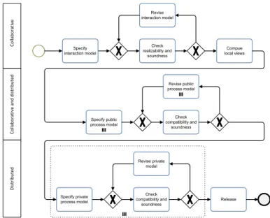
The process of modeling cross-organizational processes (cf. Fig. 2.10) can be enhanced by adding steps for verifying the presented criteria. Fig. 2.21 illustrates when soundness, compatibility and realizability are verified.
2.4 Business Process Compliance
Specify interaction model
Check realizability and
soundness
Compue local views
Specify public process model
Check compatibility and
soundness Revise interaction model
Revise public process model
Specify private process model
Check compatibility and
soundness Revise private
model
Release
CollaborativeDistributedCollaborative and distributed
Figure 2.21: The process of modeling cross-organizational processes
When considering the resource, time, data, time, and interaction process perspectives, additional soundness criteria become necessary. For example, the data perspective requires the values of data objects to be written before accessing them [RD97, RD97, RRMD09].
Time constraints, in turn, must not conflict with each other [LRW16, KSB15], and human resource assignment must ensure that for each activity there is at least one resource that is allowed to perform the activity [CRC11].
For the sake of brevity, a detailed presentation of the correctness criteria is omitted.
Interested readers are referred to [RD97, RRMD09, CRC11, RW12, KSB15, LRW16].
2.4 Business Process Compliance
Even if a process model is structurally and behaviorally correct, it still might be semanti- cally incorrect, i.e., violate domain-specific compliance rules.
Business process compliance summarizes languages, techniques and methods that aim to ensure compliance of business processes with a set of semantic constraints.
Example 2.19 (Compliance rules)
Table 2.8 lists five examples of compliance rules that refer to the X-ray examination process (cf. Examples 2.2 and 2.8).
As opposed to the structural and behavioral correctness criteria presented in Section 2.3, business process compliance not only needs to be ensured for the modeling phase and the