Monitoring Business Process Compliance Using Compliance Rule Graphs
Linh Thao Ly1, Stefanie Rinderle-Ma2, David Knuplesch1, and Peter Dadam1
1 Institute of Databases and Information Systems, Ulm University, Germany
2 Faculty of Computer Science, University of Vienna, Austria {thao.ly,david.knuplesch,peter.dadam}@uni-ulm.de,
stefanie.rinderle-ma@univie.ac.at
Abstract. Driven by recent trends, effective compliance control has be- come a crucial success factor for companies nowadays. In this context, compliance monitoring is considered an important building block to sup- port business process compliance. Key to the practical application of a monitoring framework will be its ability to reveal and pinpoint viola- tions of imposed compliance rules that occur during process execution. In this context, we propose a compliance monitoring framework that tack- les three major challenges. As a compliance rule can become activated multiple times within a process execution, monitoring only its overall enforcement can be insufficient to assess and deal with compliance vi- olations. Therefore, our approach enables to monitor each activation of a compliance rule individually. In case of violations, we are able to de- rive the particular root cause, which is helpful to apply specific remedy strategies. Even if a rule activation is not yet violated, the framework can provide assistance in proactively enforcing compliance by deriving measures to render the rule activation satisfied.
1 Introduction
In many application domains of information systems, business process compli- ance is increasingly gaining importance. In healthcare, for example, medical guidelines and clinical pathways should be followed during patient treatments.
In the financial sector, regulatory packages such as SOX or BASEL III have been introduced to strengthen customers’ confidence in bank processes. Finally, collections of quality controls, e.g., Six Sigma or ITIL, are of particular impor- tance for the internal control of business processes. In this paper we assume an example scenario that is set in bank accounting, where a variety of rules and policies exists (e.g., as a result of risk management). A selection of such rules is listed below:
c1 Conducting a payment run creates a payment list containing multiple items that must be transferred to the bank. Then, the bank statement must be checked for payment of the corresponding items. In order to avoid fraud and errors, the pay- ment list must be transferred to the bank only once.
c2 For payment runs with amount beyonde10,000, the payment list has to be signed before being transferred to the bank and has to be filed afterwards for later audits.
Example of an observed event trace T:
e1 = (payment run, payment list A, amount = €60,000) Reporting
Monitoring cockpit Monitoring cockpit
A B
e2 = (transfer to bank, payment list A) e3 = (check bank statement, payment list A) e4 = (file payment list, payment list A)
( t fi d it 1)
Monitoring cockpit Monitoring cockpit
C3 Instance 1 of C3
Instance 2 of C3 Instance 3 of C3 Instance 4 of C3
e5 = (payment confirmed, item 1) e6 = (payment confirmed, item 2) e7 = (mark as cleared, item 2) e = (payment confirmed item 3) Compliance monitoring
e8 = (payment confirmed, item 3) e9 = (mark as cleared, item 3) e10 = (put on payment list, item 3) Event service
Process execution
…
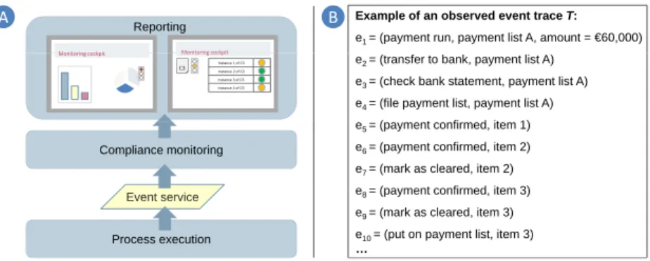
Fig. 1.General compliance monitoring architecture and events from the bank account- ing case
c3 When payment of an open item is confirmed in the bank statement, the item has to be marked as cleared eventually.
c4 Once marked as cleared, the item must not be put on any payment list.
c5 If an open item is not marked as cleared within 30 days, the bank details may be faulty. Thus, the bank details have to be (re)checked.
One way to ensure business process compliance is to verify the models of the affected business processes implemented within process-aware information systems against such imposed rules in order to achieve compliance by design. For that purpose, a multitude of approaches for business process model checking has been proposed in literature. However, design time checks are not quite sufficient as in many application domains, business process models are rarely documented or adhered to. To support business process compliance in such scenarios, it must be possible to monitor whether process executions (regardless whether an explicit process model exists) comply with imposed rules.
1.1 Challenges for Compliance Monitoring
Fig. 1A depicts a general compliance monitoring architecture. The events ob- served from process execution provide the basis for compliance monitoring. The actual low-level execution events may also be aggregated to meaningful events and then provided to the monitoring tier using event processing frameworks (e.g., complex event processing [1]). The monitoring tier, in turn, monitors com- pliance with imposed rules. It provides input to the reporting tier, where the results are visualized in accordance with the needs of the stakeholders involved.
We assume that events such as the events from the bank accounting case listed in Fig. 1B can be provided by the event service. Clearly, the information that the monitoring tier is capable of providing constitutes the basis for presentation and visualization to stakeholders such as the process supervisor. This raises three fundamental challenges that we will discuss using the bank accounting case.
Challenge 1: Identification and monitoring of individual activations of a compliance rule Consider again compliance rule c4. Then, a closer look at trace T from Fig. 1B reveals that c4 is violated over T as item 2 and item 3 are already marked as cleared butitem 3 is still put on a payment list again. In order to effectively deal with such violations, it is not sufficient for the monitoring tier just to identify that c4 is violated. Imagine that multiple other items are also marked as cleared withinT. Then, it becomes very difficult to pinpoint the item(s) causing violations. Hence, the monitoring tier must provide fine-grained compliance feedback such that it becomes possible to pinpoint the violation.
In this example, twoactivationsofc4are present in the execution, namely for item 2 anditem 3. We refer to an event pattern that activates a compliance rule as a rule activation. For example,c4becomes activated when an item is marked as cleared. As activities can be carried out multiple times, e.g., for different items, there can be multiple activations of a compliance rule in a process execution3. As the example also shows, the activations can be in different compliance states.
For example, the activation for item 3 is violated while the one for item 2 is not. Therefore, the monitoring tier must be able to identify the rule activations and to provide information on their individual compliance state as the basis for effectively assessing and dealing with incompliance.
Challenge 2: Proactive prevention of violations Generally, each activation of a compliance rule can be in one of three compliance states in a stage of process execution: satisfied, violated, or violable. Satisfied and violated are permanent states. For example, the activation ofc4foritem 3 is violated while the activation of c3 for item 2 is satisfied. A violable activation, however, can become both violated or satisfied depending on the events observed in the future.
The state violable can have very different semantics depending on the rule activations. Consider for example the activation ofc3 foritem 1 (referred to as ACT1) and the activation of c4 for item 2 (referred to as ACT2). Then, both are violable as ACT1 can become violated if item 1 is not marked as cleared in the future and ACT2 can become violated ifitem 2 is put on a payment list again. Obviously, different measures are necessary to render ACT1 and ACT2 satisfied. In order to proactively prevent violations, the monitoring tier has to make the state violable more transparent to process supervisors. In particular, support with regard to how to render an activation satisfied is desirable. Being aware that ACT1 can be rendered satisfied by marking item 1 as cleared, a process supervisor may, for example, schedule this task. To our best knowledge, challenge 2 has not been addressed yet.
Challenge 3: Root cause identification in case of violations The iden- tification of violations is only a first step. A rule activation can become vio- lated, when required events were not observed or prohibited events were observed within a particular scope. Particularly for more complex rules, a violation can
3 Note that there can also be rules that are only activated once, e.g., cardinality rules.
We consider them as being activated upon the process start.
Reportingp g
Modeling
Compliance monitoring Compliance
requirements
g
E t i
Compliance rule graphs (CRG)
Process execution Event service
3
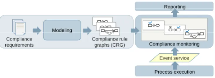
Fig. 2.Fundamental architecture of the SeaFlows compliance monitoring framework
have multiple causes, each of which may require different compensation mech- anisms. Therefore, being able to identify the root cause of a violation would facilitate the application of adequate compensation.
1.2 Contributions
In this paper, we propose an approach developed in the SeaFlows project4that tackles these three challenges. The basic architecture of the framework is de- picted in Fig. 2. We adopt a graph-based compliance rule language referred to as Compliance Rule Graphs (CRG) [2]. Our approach enables to “instantiate”
a CRG each time a new activation of it is observed and thus to individually monitor the activations. As a result, feedback can not only be provided on the overall enforcement of a compliance rule but also on its activations. Our mon- itoring approach is based on a pattern matching mechanism that exploits the structure of CRGs for monitoring and introduces markings to indicate observed event patterns that are relevant to the compliance rule to be checked. From the markings, it is possible to derive measures to proactively prevent violations in case of violable rule activations, for example to derive pending activities. For violated activations, we can derive the root cause from the markings.
In the following, we first introduce necessary fundamentals on CRGs in Sect. 2. The monitoring framework is then presented in Sect. 3. Sect. 4 intro- duces our proof-of-concept implementation. In Sect. 5, we discuss related work.
Sect. 6 summarizes the paper and provides an outlook on future research.
2 Compliance Rule Graph Fundamentals
For our monitoring framework we adopted compliance rule graphs (CRG), a graph-based compliance rule modeling language [2], as the graph structure has some advantages that we can exploit for monitoring as we will later show. The CRG language adopts the typical rule structure (i.e., if some conditions apply, then some consequence must also apply). As we address compliance rules on the occurrence, absence, and ordering relations of events, the rule antecedent
4 www.seaflows.de
and rule consequences are constituted by event patterns, respectively. Their ex- plicit structure makes it easier to comprehend CRGs than for example complex logic formulas. For brevity reasons, we will focus on compliance rules with only one consequence event pattern in this paper. Our approach is, however, also applicable to compliance rules with multiple consequence patterns.
Based on the assumption adopted from graph-based process modeling lan- guages that a graph is a suitable representation for expressing occurrence and ordering relations of events, the event patterns associated with the rule an- tecedent and the rule consequence are modeled by means of directed graphs.
In order to distinguish between the antecedent and the consequence, they are modeled using designated node types (condition and consequence node types).
Thus, from their looks, CRGs are acyclic directed graphs with different node types with a graph fragment describing the rule antecedent pattern and a graph fragment describing the rule consequence pattern.
These event patterns can be modeled using occurrence nodes, i.e., nodes that represent the occurrence of events of associated type and properties (e.g., data conditions) and edges constraining their ordering (similar to what we are used to from process modeling)5. Beside occurrence nodes, absence nodes representing the absence of certain events can be used to further refine the event patterns.
By combining these modeling primitives, it is possible to model sophisticated event patterns, which can serve as antecedent or consequence of a CRG. Def. 1 provides a basic definition of CRGs.
Definition 1 (Compliance rule graph).A compliance rule graph is a 7-tuple R= (NA, NC, EA, EC, EAC, nt, p)where:
– NA is a set of nodes of the antecedent graph ofR, – NC is a set of nodes of the consequence graph of R, – EA is a set of directed edges connecting nodes ofNA, – EC is a set of directed edges connecting nodes ofNC,
– EAC is a set of directed edges connecting nodes of the antecedent and the consequence graph ofR,
– nt : NA∪NC → {AnteOcc,AnteAbs,ConsOcc,ConsAbs} is a function as- signing a node type to the nodes ofR, and
– pis a function assigning a set of properties (e.g., activity type, data condi- tions) to each node ofR.
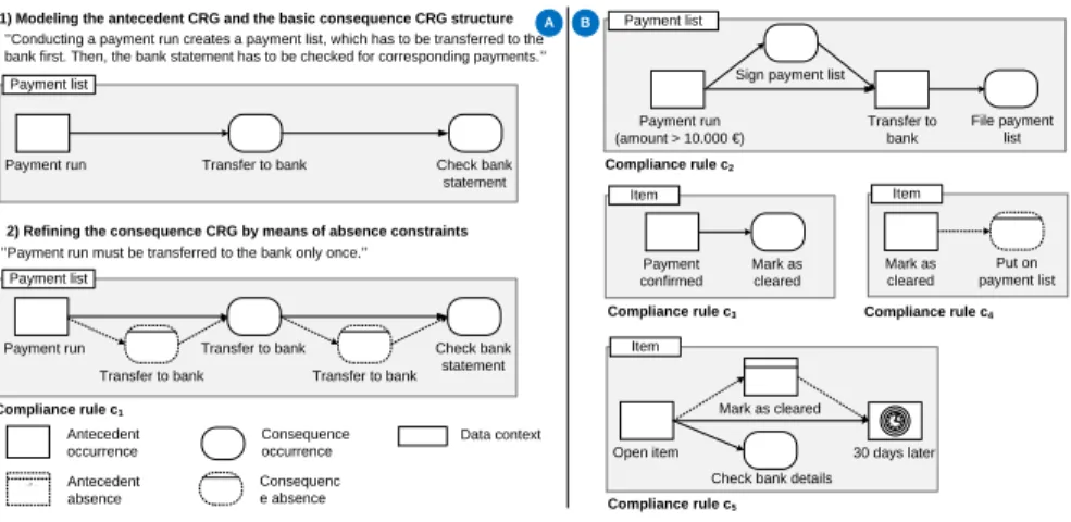
Assuming an existing event model, Fig. 3A depicts the modeling of the CRG for compliance rulec1 in two steps. Apparently,c1 is activated by thepayment runcreating apayment list. This is modeled through the correspondingAnteOcc node. As c1 requests the payment run to be followed by the eventtransfer to bankand the subsequent eventcheck bank statementfor the createdpayment list, ConsOccnodes are used to model this consequence pattern. In a second step, the consequence CRG is refined to capture the condition that thepayment listmust
5 Note that the antecedent pattern can also be left empty to model for example car- dinality constraints.
Consequence occurrence Consequenc e absence Antecedent
occurrence Antecedent absence vard
Data context
’’Conducting a payment run creates a payment list, which has to be transferred to the bank first. Then, the bank statement has to be checked for corresponding payments.’’
’’Payment run must be transferred to the bank only once.’’
1) Modeling the antecedent CRG and the basic consequence CRG structure
2) Refining the consequence CRG by means of absence constraints
Compliance rule c2
Compliance rule c3 Item
Payment confirmed
Mark as cleared
Compliance rule c4 Mark as cleared
Put on payment list Item
Compliance rule c5 Open item
Mark as cleared
30 days later Check bank details Item
A B
Payment list
Payment run Transfer to bank Check bank
statement Transfer to bank Transfer to bank
Compliance rule c1 Payment list
Payment run Transfer to bank Check bank
statement
Payment run (amount > 10.000 €)
Transfer to bank Sign payment list Payment list
File payment list
Fig. 3.Step by step modeling CRG forc1 (A) and CRGs forc2-c5(B)
be transferred to the bank only once. This condition is captured by ConsAbs nodes signifying the requested absence of additional events of type transfer to bank. In this manner, we can also model the other compliance rule examples by means of CRG as depicted in Fig. 3 B. For example, the CRG for compliance rule c5 expresses that in case an open item event is followed by a time event representing 30 days later without having recorded mark as cleared, the bank details have to be checked. Note that we assume an event processing framework that can deliver such time events.
Intuitively, an event pattern of a CRG (regardless of whether it is an an- tecedent or a consequence pattern) matches a set of events if the occurrence nodes and the ordering relations match a set of nodes and the absence constraints expressed through the absence nodes are satisfied. If the antecedent pattern is composed from onlyAnteAbsnodes, then there can be only one match of the an- tecedent (if the absence constraints apply). Each match of the antecedent event pattern constitutes an activation of the corresponding CRG. For example, the sequence of the events e1 (payment run with amount beyonde10,000) and e2
(payment list A is transferred to the bank) from Fig. 1 constitutes a match of the antecedent of c2. CRGs with empty antecedent pattern are activated upon the process start.
Definition 2 (Semantics of CRGs). Let R = (NA, NC, . . .) be a CRG and σ=< e1, . . . , en>be an execution trace. Then,R is satisfied overσiff:
– for R with non-empty antecedent pattern holds: for each match of the an- tecedent pattern ofR in σ, there is also a corresponding match of R’s con- sequence pattern inσand
– for R with empty antecedent pattern holds: there is also a match of R’s consequence pattern inσ.
Due to their explicit structure, verbalization, a technique known from busi- ness rule modeling, can be easily realized for CRGs. While CRG is a compo-
e5= (payment confirmed, item 1)
End of process execution e8= (payment confirmed, item 3)
e7= (mark as cleared, item 2)
e9= (mark as cleared, item 3) e6= (payment confirmed, item 2) Compliance rule c3:
Payment confirmed
Mark as cleared
Item Item 1 ms1 Item 1 ms1
ms2
Item 2 Item 2 ms3
ms4
Item 3
ms6
Item 1 ms1
Item 1 ms1
Item 1
ms3
Item 2 Item 2 ms3
ms5
Item 3 Item 3 ms5
ms3
Item 2 ms1
Item 1
Node markings:
NOT_EXECUTED EXECUTED NULL
Activation A1
Activation A2
Activation A1
Activation A2
Activation A1
Activation A2
Activation A1
Activation A2
Activation A1
Activation A2
Activation A1
Activation A3 Activation A3 Activation A3
Fig. 4.Observed patterns with regard to CRGc3 when processing eventse5 -e9
sitional language, we can also use CRGs to model frequent rule patterns, for example [3]. Due to space limitations, we abstain from going into further details on the properties of CRGs (e.g., syntactic correctness, further modeling primi- tives). Further details can be found in [2]. In this paper, we only focus on a subset of the CRG language that is sufficient to illustrate our monitoring framework.
3 Compliance Monitoring
Generally, it would be possible to monitor compliance with an imposed CRG by transforming it into an automaton or by generating event queries (e.g., for complex event processing [1]) from it. The benefits and drawbacks of these ap- proaches are discussed in Section 5. For example, addressing challenge 1 is cum- bersome when employing the automaton approach [4]. The beauty of our ap- proach is that no transformation of the modeled compliance rules (in the form of CRGs) into other representations is necessary in order to enable monitoring.
A CRG is instead monitored by exploiting its graph structure. Thus, feedback can be provided specifically on the basis of the structure of the very CRG leaving no gap between the modeled rule and the feedback mechanism.
The basic idea behind the approach is illustrated by Fig. 4 using the example of CRGc3. Fig. 4 depicts event patterns that are relevant toc3and that become observable in different stages of process execution when processing the events of trace T from Fig. 1. Instead of textually describing these patterns, we use the graph structure of CRGs and node markings that indicate whether or not an event was observed to capture these observable patterns. New patterns are marked in grey color.
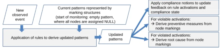
Ne Current patterns represented by
Apply compliance notions to update feedback on rule activations and New
observed event
p p y
marking structures (start of monitoring: empty pattern, where all nodes are assigned NULL)
compliance state For violable activations:
Derive preventive measures from node markings
Application of rules to derive updated patterns For violated activations:
Derive root cause from node markings
Updated patterns
Fig. 5.Updating compliance feedback when a new event is observed
Example 1 Consider Fig. 4 and c3. Then, after observing e1-e5, the pattern
“payment confirmedforitem 1 without subsequentmark as cleared yet” becomes observable in the execution trace. This pattern is captured byms1using the node stateExecutedto indicate thatpayment confirmedwas already observed. When observinge6, a similar pattern can be formed foritem 2. Obviously,ms1andms2
each constitutes an activation ofc3. When observinge7,ms2is no longer current but instead, the situation can be represented byms1andms3, wherems3reflects the pattern “payment confirmed for item 2 with subsequent mark as cleared”.
Thus, ms3 constitutes a satisfied activation of c3. Observation of e8 yields a new pattern for item 3 represented by ms4. This pattern is replaced by ms5 after item 3 is marked as cleared (event e9). If the process execution would be terminated,ms1 would be no longer current for activationA1asitem 1 will not be marked as cleared. Thus,ms1is updated toms6. Altogether, after execution ofe1-e9and the termination of the process execution, the compliance withc3 is reflected by the patterns ms6,ms3, andms5, where each of this represents an activation of c3. While the activations A2 and A3 are satisfied as the required events were observed, activationA1 foritem 1 is violated as it was not marked as cleared as indicated by theConsOccnode marked withNotExecuted.
In the example, we built the observable patterns manually. Inspired by pat- tern matching, our monitoring framework automatically identifies all activations of a CRG to be checked and further tries to identify a match of the consequence pattern in the execution trace. For that purpose, it builds such patterns based on the graph structure of the CRG to be checked that become observable in the partial execution trace as illustrated in the example. However, in the monitoring framework, these patterns are not built from scratch each time a new event is observed. Instead, new observable patterns are derived from existing patterns by applying defined rules when observing a new event. Fig. 5 summarizes the overall procedure when a new event is observed.
Each relevant observable pattern represented by marking the CRG as illus- trated in the example is stored in a data structure calledmarking structure (in brief MS). From the node semantics and the node markings, it can be derived whether a MSrepresents a rule activation. Also the individual compliance state of the rule activation can be determined this way (challenge 1). For a violable rule activation, measures can be derived from the node markings to proactively enforce the satisfaction, for example, the pending activities can be identified
(challenge 2). In case of violation, the node markings further enable root cause analysis without additional cost (challenge 3).
In the following, we first formalize theMSs and introduce formal notions to assess them with regard to compliance in Section 3.1. In Section 3.2, we introduce the algorithm for deriving updated observed patterns from old patterns when a new execution event is observed. Finally, we further show how the challenges 2 and 3 can be dealt with in Section 3.3.
3.1 CRG Markings and Compliance Notions
In Fig. 4, we already introduced the node markings that are used to indicate whether or not an event was observed: A CRG nodenmarked withNullsignifies that no matching event is observed yet. Regardless of the node type, a CRG node n in a pattern marked with Executed means that a matching event has been observed. A CRG nodenmarked with NotExecutedmeans that the associated event has not been and will not be observed (e.g., when the window for an event to occur has elapsed). Using the node markings, we can use the specific CRG structure to express relevant patterns that become observable in the execution trace. During compliance monitoring for a CRG, each such pattern is captured in a data structure calledmarking structure (MS), e.g.,ms1in Fig. 4. In particular, a MS captures a (potential) activation of a CRG observable from the trace. It contains a marking for each antecedent node of the CRG and multiple markings for the CRG’s consequence pattern6. Def. 3 formalizes the notion ofMSs.
Definition 3 (CRGMS).LetR= (NA, NC, . . .)be a CRG andN odeStates:=
{Null,Executed,NotExecuted} be the set of execution states of CRG nodes.
Then, a CRG MSofR is defined as a 3-tuple
ms:= (nsA, evA,{(ns1C, evC1), . . . ,(nskC, evCk)})where
– nsA:NA→N odeStates is a function assigning an execution stateto each node ofA.
– evA is a function assigning an observed execution event (or a dummy event in case nsA(n) ∈ {Null,NotExecuted}) to each node of A. We denote (nsA,evA) asAnteMark ofR.
– nsiC:NC→N odeStatesis a function assigning an execution stateto each node ofC.
6 The rationale behind this is that depending on the particular CRG, the pattern matching procedure may has to try different options to form a match of the con- sequence pattern out of the events contained in the execution trace. Consider for example the rule “After A, there has to a B that is not followed by a C”. Then, assuming that an A is present in the trace, the first subsequent B may not lead to a match of the consequence as it can still be followed by a C. In this case, it becomes necessary to also explore other options, which results in multiple markings for the consequence pattern. This only becomes necessary for the particular case of ConsOccnodes with direct ConsAbs successors and is taken into account by our pattern matching mechanism (cf. Section 3.2).
– eviC is a function assigning an observed execution event (or a dummy event in case nsiC(n) ∈ {Null,NotExecuted}) to each node of C. We denote (nsiC,evCi )asConsMark ofR.
Example 2 Considerms1 from Fig. 4:
– ms1= (nsA, evA,{(nsC, evC)}) with
– nsA(payment conf irmed) =Executed,evA(payment conf irmed) =e5, – nsC(mark as cleared) =Null, andevC(mark as cleared) =no event.
As illustrated by Fig. 4, in each stage of process execution, the compliance with an imposed CRG can be reflected by a set ofMSs. To assess theseMSs, we can benefit from the node semantics and the node markings. Generally, for a CRG’s antecedent or consequence pattern composed from occurrence and ab- sence nodes, a match in the execution trace is found if all events associated with occurrence nodes are observed (i.e., marked as Executed) and for all absence nodes, no matching events were observed (i.e., marked asNotExecuted). If the antecedent is marked accordingly, the correspondingMSconstitutes an activation of the CRG. Recall that a rule activation is satisfied if a match of the CRG’s consequence can also be found in the execution trace. Thus, the activation is satisfied if the MSalso contains aConsMarkthat is marked as described. Def. 4 formalizes this intuition:
Definition 4 (Compliance Notions for MSs). Let R = (NA, NC, . . .) be a CRG andms= (nsA, evA,{(ns1C, evC1), . . . ,(nskC, evCk)})be a MSofR. Then,
– we will sayms isactivatedif the following holds:
• ∀n∈NA:nt(n) =AnteOcc⇒nsA(n) =Executed∧
∀n∈NA:nt(n) =AnteAbs⇒nsA(n) =NotExecuted
For anactivatedms, we further distinguish between the following states:
– msissatisfiedif the following holds:
• ∃nsiC, i∈ {1, . . . , k}:
(∀n∈NC :nt(n) =ConsOcc⇒nsiC(n) =Executed)∧
(∀n∈NC :nt(n) =ConsAbs⇒nsiC(n) =NotExecuted) – msisviolatedif the following holds:
• ∀nsiC, i∈ {1, . . . , k}:
(∃n∈NC :nt(n) =ConsOcc⇒nsiC(n) =NotExecuted)∨
(∃n∈NC :nt(n) =ConsAbs⇒nsiC(n) =Executed) – Otherwise,ms is consideredviolable.
Example 3 Consider again Fig. 4. Then,
– ms1,ms3, andms6are allactivated, i.e., they constitute activations ofc3. – ms1isviolable,ms3 issatisfied, whilems6 isviolated.
Def. 4 enables us to assess obtained MSs. Altogether, this enables the process supervisor to get an overview on rule activations in the process execution and provides basic information on their compliance state. In Section 3.3, we will fur- ther discuss how the monitoring framework can be used to assist the process supervisor in identifying the root cause for violations and even in preventing violations. Before that, we first introduce the pattern matching mechanism op- erating on MSs behind our framework in Section 3.2.
3.2 The Pattern Matching Mechanism
As mentioned, eachMSrepresents a (potential) activation of the CRG. As indi- cated in Fig. 5, the monitoring of a CRG starts with a MSwhere all nodes are assigned Null (i.e., no events observed yet). How to derive updated MSs from existingMSs when a new event is observed? The pattern matching mechanism of the framework is based on three considerations:
1: The objective is to identify all rule activations present in the execution trace. For that purpose, it becomes necessary to explore different options to form a match of the CRG’s antecedent pattern out of the events in the trace in the pattern matching process.
2:For eachMS, the objective is further to identify a match of the consequence CRG (cf. Def. 2). For that purpose, we try to explore only one option if possible to increase the efficiency. Alternative options are only explored if necessary.
3: Exploit the ordering of nodes for pattern matching: A node can only match an event, if the node and event specification match and the node is not yet assigned to another event. Additionally, also matching events for rel- evant predecessors must have already been found. In particular, for AnteOcc andAnteAbsnodes,AnteOccpredecessors must be already marked asExecuted.
For ConsOcc and ConsAbs nodes, AnteOcc and ConsOcc predecessors must be marked asExecuted.
Based on these considerations, algorithm 1 derives updated patterns from a MS when an event is observed. The outer loop implements consideration 1.
The inner loop in line 19 updates the observable patterns with regard to the consequence CRG (represented by the ConsMarks). It further implements con- sideration 2, as only for particular nodes, namely ConsOcc nodes with direct ConsAbssuccessors, alternative options have to be explored.
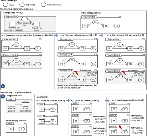
Example 4 Fig. 6A applies algorithm 1 to c2 over the events < e1, e2, e4 >7. NewMSs are highlighted. The monitoring starts withms1. Whene1 is observed, application of algorithm 1 yields both ms1 and ms2. Here, ms1 enables the recognition of future activations of c2, whilems2 explores whether e1 leads to a rule activation8. So far, no activation of c2 is observed yet. When observing
7 e3is irrelevant toc2.
8 Note that when manually conducting pattern matching (cf. Fig. 4), we would typ- ically not identifyms1. However, such not yet matching patterns are important to enable automatically deriving updated patterns from existing patterns.
Algorithm 1Deriving updated patterns from aMSover an event 1:R= (A, C, . . . , . . .) is a CRG;eis an observed event;M SRes=∅; 2:ms= (nsA, evA,{(ns1C, evC1), . . . ,(nskC, evkC)}) is aMSofR;
{CRG nodes that matche(cf. consideration 3):}
3:NAnteOccis the set ofAnteOcc,NAnteAbsis the set ofAnteAbsnodes matchinge; 4:NConsOcci , i= 1, . . . , k; is the set ofConsOccnodes matchingeof (nsiC, eviC);
5:NConsAbsi , i= 1, . . . , k; is the set ofConsAbsnodes matchingeof (nsiC, eviC);
6:for allQ∈ P(NAnteOcc)do 7: create a copyms0ofms;
8: for alln∈Qdo
9: ns0A(n) =Executed;ev0A(n) =e;
10: mark allAnteAbspredecessors ofnwithns0A(n) =NullasNotExecuted;
11: for allConsMarks (nsiC, eviC) ofms0do
12: mark allConsOccpredecessors ofnwithnsiC(n) =NullasNotExecuted;
13: mark allConsAbspredecessors ofnwithnsiC(n) =NullasNotExecuted;
14: end for 15: end for
16: for allnwithn∈NAnteAbs∧ns0A(n) =Nulldo 17: ns0A(n) =Executed;ev0A(n) =e;
18: end for 19: CM=∅;
20: for allConsMarkscm= (nsiC, evCi) ofms0do
21: N=NConsOcci \{n∈NC|nt(n) =ConsOcc∧nsiC(n) =NotExecuted};
22: D={n∈N|n has no directConsAbssuccessor};
23: I=N\D;
24: for allQ=D∪T, T∈ P(I)do 25: create a copycm0= (ns0Ci,evC0i) ofcm;
26: for alln∈Qdo
27: ns0iC(n) =Executed;ev0iC(n) =e;
28: mark allConsAbspredecessors ofnwithns0iC(n) =NullasNotExecuted;
29: end for
30: for allnwithn∈NConsAbsi ∧ns0Ci(n) =Nulldo 31: ns0Ci(n) =Executed;ev0Ci(n) =e;
32: end for
33: CM=CM∪ {cm0}; 34: end for
35: end for
36: setConsMarks ofms0=CM;
37: M Sres=M Sres∪ {ms0}; 38:end for
39:return M Sres;
e2, ms1 remains unaffected. However, ms2 results inms2 andms3. Here, ms2
enables the recognition of possible future rule activations in combination withe1. The compliance notions (cf. Def. 4) reveal thatms3 constitutes an activation of c2,A1, that is alreadyviolatedas the payment list was not signed before being transferred to the bank. In this case, the process supervisor can be notified. If in practice the activity transfer to bank can be put on hold, the system could even suspend its execution being aware that the activity leads to incompliance.
Despite the violation, the monitoring of A1 can still be continued. Thus, when observinge4,ms3yieldsms4. ActivationA1is still violated, but nevetheless due to one but not two causes as we will later discuss in Section 3.3.
Example 5 Fig. 6B applies algorithm 1 to c4 over the events < e7, e9, e10 >.
As mark as cleared occurs twice the execution (as e7 for item 2 and as e9 for
File payment list
e4 = (file payment list, payment list A) e2 = (transfer to bank, payment list A)
Compliance rule c2:
NOT_EXECUTED EXECUTED
NULL
PR TB
SL
FL
Payment list ms1
PR TB
SL
FL
Payment list ms1
PR TB
SL
FL
Payment list A ms3
PR TB
SL
FL
Payment list A ms2
PR TB
SL
FL
Payment list ms1
PR TB
SL
FL
Payment list A ms4
PR TB
SL
FL
Payment list A ms2
- ACTIVATED - VIOLATED
Monitoring of activation for payment list A can still be continued
Activation A1 Activation A1
- ACTIVATED - VIOLATED
e10 = (put on payment list, item 3) A
e1 = (payment run, payment list A, amount = €60,000)
PR TB
SL
FL
Payment list ms1
PR TB
SL
FL
Payment list A ms2
Payment run
(amount > 10.000 €) Transfer to bank Sign payment
list Payment list
Initial empty pattern:
Node markings:
Monitoring compliance rule c2:
Monitoring compliance rule c4: Compliance rule
c4
Mark as cleared
Put on payment list Item
M P
Item ms1
M P
Item 3 ms4
M P
Item ms1
M P
Item 2 ms2
- ACTIVATED - VIOLABLE
- ACTIVATED - VIOLATED Activation A2
Activation A1
e9 = (mark as cleared, item 3)
M P
Item 3 ms3
M P
Item ms1
M P
Item 2 ms2
- ACTIVATED - VIOLABLE
- ACTIVATED - VIOLABLE Activation A1
Activation A2
e7 = (mark as cleared, item 2)
M P
Item ms1
M P
Item 2 ms2
Initial empty pattern:
B Monitoring:
e10 = (put on payment list, item 3)
Fig. 6.Monitoringc2 over< e1, e2, e4>(A) andc4 over< e7, e9, e10>(B)
item 3), compliance monitoring reveals two activations of c4, namely A1 and A2, after observing e7 and e9. At that stage, both activations are violable.
However, item 3 is later put on a payment list again (indicated by e10). As a result, activationA2 becomes violatedas the absence constraint is violated.
3.3 Prevention of Violations and Root Cause Analysis
Prevention of violations Aviolablerule activation can become bothsatisfied orviolateddepending on future events. Due to its graph notation, such aMScan be presented to the process supervisor if required in order to identify measures to prevent a violation. Additionally, the system can assists in preventing viola- tions by deriving concrete actions in order to render the activationsatisfied.
Based of Def. 4, the rule activation becomes satisfied when a match of the consequence is found. Thus, from a ConsMark(nsC, evC) that can still lead to
a match of the consequence, we can derive actions to satisfy the corresponding activation as follows:
– EachConsOcc node n withnsC(n) =Null represents a still pending ac- tivity.
Possible action: Schedule the pending activity9.
Example: Considerms1 from Fig. 4. Then, ConsOcc node mark as cleared is pending as it is still marked asNull. To satify this activation, the corre- sponding activity can be scheduled, for example, by putting it into an agent’s worklist.
– EachConsAbsnodenwithnsC(n) =Nullthat does not have anyConsOcc predecessors still in stateNull represents anactive absence constraint. The absence of the corresponding event is necessary in order for thisConsMark to constitute a match of the consequence CRG.
Possible action: Deactivate the corresponding activity until n is marked asNotExecuted(e.g., when the window ofnelapsed).
Example: Consider ms2 from Fig. 6B. Then, ConsAbs node put on pay- ment list represents an active absence constraint. As no ConsOccnodes are pending, immediate end of process execution would render this activation satisfied. To enforce compliance, the activity put on payment list can be deactivated foritem 2.
As the pattern matching mechanism employs a rather greedy strategy to iden- tify a match of the consequence, the thus derivied action chains constitute the
“shortest” ways to enforce compliance.
Root cause identification In a similar manner to violation prevention, the root cause of a violated rule activation can be easily derived from a ConsMarks.
Generally, an activation can become violated if required events do not occur or / and prohibited events occur during process execution. These causes are also reflected in theMS. For aConsMark(nsC, evC) of aviolated MS, we can identify why it does not constitute a match of the consequence CRG:
– EachConsOcc node n with nsC(n) = NotExecuted represents arequired activity missingin the pattern.
Example: Considerms4from Fig. 6A. Then, the missing eventsign payment list before transferringpayment list Ato the bank can be precisely identified as the root cause for the violation of rule activationA1.
– EachConsAbs node n with nsC(n) = Executedrepresents an prohibited activity observedin the pattern.
Example: Consider ms4 from Fig. 6B. Then, the prohibited event put on payment list foritem 3 is identified as the root cause for the violation.
9 Since CRGs are acyclic, we can further derive a process to be scheduled by adopting the ordering relations of the occurrence nodes in case multiple activities are pending.
Fig. 7.Execution ofc2 over< e1, e2, e4>andms4 as one of the resultingMSs
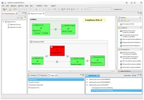
4 Implementation
We impemented our monitoring approach in the SeaFlows Toolset [5] that com- prises a variety of tools for supporting compliance throughout the process lifecy- cle. The SeaFlows Compliance Monitor is integrated into the AristaFlow BPM Suite that is based on ADEPT [6]. CRGs are modeled using a graphical editor and stored as XML files. For convenient compliance rule modeling, the SeaFlows Compliance Rule Editor allows for modeling parametrized compliance rules pat- terns that can be reused whenever a rule with a similar structure is required.
Fig. 7 shows the rule activation captured byMSms4(cf. Fig. 6A) obtained when observing the event sequence < e1, e2, e4 >from Fig. 1. The root cause of the violation is visualized directly in the CRG by using the node markings and the color highlighting. This enables process supervisors to easily pinpoint violations and to apply root cause specific remedies, for example initiate an audit activity as the transferred payment list was not signed before being transferred to the bank.
5 State-of-the-art
Most work addressing process monitoring focus on data consistency or process performance (e.g., KPI monitoring or business activity monitoring). Several ap- proaches address root cause analysis in the context of design time verification [7, 8, 5]. Generally, for a predefined set of rule patterns, possible types of violations
can be anticipated, which can be used for root cause analysis. However, runtime monitoring of complex rules on the occurrence, absence, and ordering of particu- lar events necessitates more advanced strategies. We distinguished three classes of monitoring approaches addressing constraints on the behavior of events. In addition, compliance monitoring is also related toconformance checking.
Automaton-based monitoring One approach to monitor compliance with imposed rules is to use an automaton that reaches an accepting state if the rule to be checked is satisfied. As compliance rules are typically not modeled as automaton, they first have to be modeled using a formalism, such as linear temporal logic (LTL), from which an automaton can be generated. To hide the complexity of LTL from the modeler, graph notations for frequently used constraint patterns based on the work of Dwyer and Corbett [3], such as ConDec [9], were suggested.
Maggi et al. [10] suggest a monitoring approach based on LTL and colored au- tomata. It includes information about the accepting states of the automata of the individual constraints in a global automaton representing the conjunction of all imposed constraints. The latter is important to identify whether constraints are conflicting. In case a violation occurs, the monitoring can still be continued.
Generally, challenge 1, the support of individual rule activations, is cumbersome to tackle using automaton-based approaches as this would require an additional instantiation mechanism. In addition, it is a non-trivial task to derive meaning- ful information from a non-accepting state of a generated automaton in case of violations (e.g., root cause).
Logic-based monitoring Some approaches employ logic formalisms to conduct monitoring. In [4], Montali et al. introduce an event calculus formalization for ConDec [9] constraints, which supports the identification of constraint activa- tions. While this approach can also deal with temporal scopes, the formalization was done for existence, absence, and response constraints. Alberti et al. [11] re- port on monitoring contracts expressed as rules using the notion of happened and expected events. At runtime, events are aggregated in a knowledge base and reasoning is employed to identify violations. It seems that proactive prevention of violations and root cause analysis were not addressed by these approaches.
Violation pattern based monitoring Incompliance with rules on the occurrence, absence, and ordering of events can also be detected by querying the (partial) execution trace for violation patterns. To conduct the querying, existing frame- works and technologies such as complex event processing (CEP) [1] are appli- cable. In [8], Awad et al. introduce anti-patterns for basic rule patterns such as precedence. While this approach addresses design time verification of process models, the anti-patterns can also be applied to query the execution trace. For simple compliance rules or basic relations (as for example introduced in [12]), all violation patterns can be anticipated. However, for more complex compliance rules on the occurrence, absence, and ordering of events that can be violated in multiple ways, automatic computation of violation patterns to identify all posssible violations becomes a real challenge. This has not been addressed yet.
In their work, Giblin et al. [13] developed the REALM rule model. For REALM patterns, such as “y must occur within time t after x”, they provide transforma- tions into ACT correlation rules, which can be used for detecting relevant event patterns. Event processing techonologies are further used by numerous compli- ance monitoring frameworks to detect violations, e.g., in the COMPAS project [14, 15]. How the event queries are generated from complex compliance rules is not the focus of these approaches.
Conformance checking Conformance checking investigates whether a process model and process logs are conform to each other. Generally, the conformance can be tested for example by replaying the log over the process model. To tackle this, several approaches were proposed [16, 17] that introduce techniques and notions such as fitness and appropriateness to also quantify conformance. Im- plementations of these approaches (e.g., the Conformance Checker) are available in the process mining framework ProM [18]. Conformance checking and compli- ance rule monitoring exhibit major differences that require different techniques.
For example, compliance rules are typically declarative while process models are mostly procedural. In addition, most of the work on conformance checking operates a posteriori. However, these approaches provide good inspiration, for example to develop metrics for quantifying compliance. Weidlich et al. show in [12] how to derive event queries for monitoring process conformance from a pro- cess model. They employ a behavioral profile that serves as an abstraction of the process model. The profile captures three relations among the activities of a process model (e.g., strict order relation). For these relations, event monitoring queries can be generated (cf. discussion on violation pattern based monitoring).
6 Summary and Outlook
In this paper, we addressed three major challenges in the context of monitoring the compliance with imposed rules. Our framework enables the identification of all activations of a compliance rule. In case of a compliance rule is violated, it becomes possible to pinpoint the rule activations involved. In addition, as our framework does not require any transformations into other representations in order to conduct the monitoring, feedback and diagnosis can be given specifically based on the corresponding rule structure. In particular, we can derive the root cause for a violation from the node markings of the particular rule. Even for rule activations that are not yet permanently violated, we can derive actions (in particular pending activities and active absence constraints) that can be helpful to process supervisors to proactively prevent violations. The validity of the approach was shown based on our proof-of-concept implementation. Our monitoring approach is not restricted to CRGs but can also be adapted to deal with other graph-based rule languages. We also conducted research to further increase the efficiency of our approach, for example by pruning paths to be explored using domination rules. In future work, we will further address the interplay of CRGs, for example conflicting rules.
References
1. Jacobsen, H.A., Muthusamy, V., Li, G.: The PADRES event processing network:
Uniform querying of past and future events. it - Information Technology (2009) 250–261
2. Ly, L.T., Rinderle-Ma, S., Dadam, P.: Design and verification of instantiable com- pliance rule graphs in process-aware information systems. In: Int’l Conf. on Ad- vanced Information Systems Engineering. (2010) 9–23
3. Dwyer, M.B., Avrunin, G.S., Corbett, J.C.: Patterns in property specifications for finite-state verification. In: Proc. ICSE’99. (1999) 411 – 420
4. Montali, M., Maggi, F., Chesani, F., Mello, P., van der Aalst, W.: Monitoring business constraints with the event calculus. Technical report, Universita degli Studi di Bologna (2011)
5. Ly, L.T., Knuplesch, D., Rinderle-Ma, S., G¨oser, K., Pfeifer, H., Reichert, M., Dadam, P.: Seaflows toolset - compliance verication made easy for process-aware information systems. In: Proc. CAiSE’10 Forum. Volume 72 of LNBIP., Springer (2010) 76–91
6. Rinderle, S., Reichert, M., Dadam, P.: Flexible support of team processes by adaptive workflow systems. Distributed and Parallel Databases16(2004) 91–116 7. Elgammal, A., Turetken, O., van den Heuvel, W., Papazoglou, M.: On the formal specification of regulatory compliance: A comparative analysis. In: Proc. ICSOC’10 Workshops. (2010)
8. Awad, A., Weske, M.: Visualization of compliance violation in business process models. In: Proc. BPI’09. (2009)
9. Pesic, M., van der Aalst, W.M.P.: A declarative approach for flexible business pro- cesses management. In Eder, J., Dustdar, S., eds.: Business Process Management Workshops. Volume 4103 of LNCS., Springer (2006) 169–180
10. Maggi, F., Montali, M., Westergaard, M., van der Aalst, W.: Monitoring business constraints with linear temporal logic: An approach based on colored automata.
In: Proc. BPM 2011. (2011)
11. Alberti, M., Chesani, F., Gavanelli, M., Lamma, E., Mello, P., Montali, M., Torroni, P.: Expressing and verifying business contracts with abductive logic. In: Normative Multi-agent Systems. Number 07122 in Dagstuhl Seminar Proceedings (2007) 12. Weidlich, M., Ziekow, H., Mendling, J., G¨unter, O., Weske, M., Desai, N.: Event-
based monitoring of process execution violations. In: Proc. CAISE 2011. (2011) 13. Giblin, C., M¨uller, S., Pfitzmann, B.: From regulatory policies to event monitoring
rules: Towards model-driven compliance automation. Technical Report Research Report RZ-3662, IBM Research GmbH (2006)
14. Holmes, T., Mulo, E., Zdun, U., Dustdar, S.: Model-aware monitoring of soas for compliance. In Dustdar, S., Li, F., eds.: Service Engineering. Springer (2011) 117–136
15. Birukou, A., D’Andrea, V., Leymann, F., Serafinski, J., Silveira, P., Strauch, S., Tluczek, M.: An integrated solution for runtime compliance governance in SOA.
In: Proc. ICSOC’10. (2010)
16. van der Aalst, W.M.P., de Medeiros, A.K.A.: Process mining and security: De- tecting anomalous process executions and checking process conformance. Electr.
Notes Theor. Comput. Sci.121(2005) 3–21
17. Rozinat, A., van der Aalst, W.M.P.: Conformance checking of processes based on monitoring real behavior. Inf. Syst.33(2008) 64–95
18. van der Aalst, W., et al.: ProM 4.0: Comprehensive support for real process anal- ysis. In: Proc. ICATPN 2007. Volume 4546 of LNCS., Springer (2007) 484–494