Compliance Rule Graph
⋆David Knuplesch1, Manfred Reichert1, Linh Thao Ly1, Akhil Kumar2, and Stefanie Rinderle-Ma3
1 Institute of Databases and Information Systems, Ulm University, Germany david.knuplesch,manfred.reichert,thao.ly@uni-ulm.de
2 Smeal College of Business, Pennsylvania State University, PA, USA akhilkumar@psu.edu
3 Faculty of Computer Science, University of Vienna, Austria stefanie.rinderle-ma@univie.ac.at
Abstract. A fundamental challenge for any process-aware information system is to ensure compliance of modeled and executed business pro- cesses with imposed compliance rules stemming from guidelines, stan- dards and laws. Such compliance rules usually refer to multiple process perspectives including control flow, data, time, and resources as well as interactions with business partners. On one hand, compliance rules should be comprehensible for domain experts who must define and ap- ply them. On the other, compliance rules should have precise semantics such that they can be automatically processed. In this context, providing a visual compliance rule language, which hides formal details from rule designers, is crucial in order to enable an intuitive way of modeling. So far, visual compliance rule languages have focused on the control flow perspective, but lack adequate support for the other perspectives. To remedy this drawback, this report introduces the extended Compliance Rule Graph language and its formal semantics.
Keywords: business process compliance, compliance rule graphs, busi- ness process modeling, business intelligence, formal semantics
1 Introduction
During the last decade, numerous approaches for ensuring the correctness of business processes have been discussed [2–5]. Most of them focus on syntac- tical correctness and process model soundness (e.g., absence of deadlocks and lifelocks). However, business processes must also comply with semantic rules stemming from domain-specific requirements such as corporate standards, le- gal regulations, guidelines or best practices [6, 7]. Summarized under the no- tion ofbusiness process compliance, existing approaches have mostly considered
⋆This work was done within the research project C3Pro funded by the German Re- search Foundation (DFG), Project number: RE 1402/2-1, and the Austrian Science Fund (FWF) under project number: I743. Parts of this technical report will be pub- lished in [1].
compliance issues related to the control flow perspective of single processes. In turn, only a few approaches consider the data, resource, and time perspectives in this context, although they are crucial as well [8–11]. Furthermore, cross- organizational scenarios characterized by interacting and collaborating business processes of various parties have not been properly considered so far [12]. In this context, compliance requirements need to be specified for both local and global processes as well. Note that this requires to consider the data, resource, and time perspectives as well as interactions between business partners (i.e. messages ex- changed) as well. As examples consider the compliance rules in Table 1, which are imposed on a cross-organizational process scenario involving the two business partners reseller and manufacturer. In particular, as shown by the highlighted terms in Table 1, compliance rules may refer to the data, time, and resource per- spectives of business processes as well as to interactions with business partners.
Compliance rule c1 refers to the interactions between a reseller and manufac- turer (request andreply) after a particular point in time (3rd January, 2013) as well as the maximum time distance between them (within three days). In turn, the data perspective of compliance rules is emphasized by compliance rule c2 of the manufacturer. It forbids changing anorder after having started the cor- respondingproduction task. Compliance rulec3 combines the interaction, time, and data perspectives. Finally, compliance rule c4 introduces the resource per- spective (member of the order processing department and another member of the same department with supervisor status). In addition,c4 considers the data perspective (e.g.new customer andtotal amount greater than e5,000) and the time perspective (at most three days). Particularly,c4 shows that the different perspectives might be relevant for the same rule and hence must not be consid- ered in an isolated manner.
When comparingc4 andc2 with c1 andc3, one can observe two different view- points: c4 and c2 are expressed from the viewpoint of the manufacturer (i.e., local view), whereas c1 and c3 reflect a global view. Note that such distinction
Table 1: Examples of compliance rules for order-to-delivery processes c1 Anyrequest sent from the reseller to the manufacturerafter January 3rd, 2013
should bereplied by the manufacturerwithin three days.
c2 After starting the production related to a particularorder, the latter must not be changed anymore.
c3 When the manufacturersends a bill with anamount lower thane5,000 to the reseller, the latter must make the paymentwithin 7 days.
c4 After receiving a production request message from the reseller, which refers to a new customer and has a total amount greater than e5,000, the solvency of this customer must be checked by amember of the order processing department.
Based on the result of this check,another member of the same department with supervisor statusmust approve the request. Finally, the approval result must be sent to the resellerat most three days after receiving the original request.
between local and global views is common to cross-organizational collaboration scenarios not only in the context of process compliance [12, 13]. For example, BPMN 2.0 provides collaboration and choreography diagrams to express these different viewpoints.
Several approaches for formally capturing compliance requirements at different abstraction levels (e.g., temporal logics [14]) exist. In particular, they also enable the automatic verification of the conformance of business processes with respec- tive compliance rules. As the use of formal languages for specifying compliance rules would be too intricate, rule patterns hiding formal detail from rule mod- elers have been proposed [9, 11]. Furthermore, a few approaches also consider more advanced issues like, for example, the use of data conditions in the context of compliance requirements. However, existing approaches are usually restricted to a specific subset of rule patterns. In turn, languages employing visual nota- tions, like the compliance rule graph approach [15] or BPSL [16], combine an intuitive notation with the advantages of a formal language. However, the meta- analyses and case studies, we conducted in domains like higher education [17], medicine [18–21] and automotive engineering [22, 23], have revealed that these visual compliance rule languages still lack support for the time, data, and re- source perspective of business processes and do not consider cross-organizational scenarios with interacting partners [12]. Overall, the following fundamental re- quirements for visual compliance rule languages need to be considered:
– In addition to the control flow perspective, the data, resource and time per- spectives of compliance requirements must be properly captured.
– To not only consider process orchestrations, but cross-organizational scenar- ios as well, it becomes necessary to integrate the interaction perspective with compliance rule languages as well.
– To provide tool support for both the modeling and verification of compliance rules, both their syntax and semantics must be formalized.
To cope with the discussed shortcomings, this report introduces the extended Compliance Rule Graph (eCRG) and its formal semantics. The eCRG builds on theCompliance Rule Graph(CRG) language developed in previous work [15, 24], but additionally comprises elements enabling the visual modeling of compliance rules with the support of the process, data, time, and resource perspectives. Fur- thermore, we introduce concepts that allow defining compliance rules in respect to message flows and partner interactions; i.e., the eCRG language is able to specify compliance requirements for cross-organizational process scenarios (i.e.
processes choreographies). For defining the formal semantics of the eCRG, we provide a transformation into FOL formula. Note that the latter can be evaluated over process traces toa posteriori verify the compliance of business processes.
Altogether, the eCRG allows capturing compliance requirements at an abstract level, while enabling the specification of verifiable compliance rules in the context of cross-organizational scenarios, including the process, data, time, and resource perspectives.
The remainder of this report is structured as follows: Section 2 discusses re- lated work. Section 3 introduces theextended Compliance Rule Graph (eCRG).
The formal semantics of the eCRG language is specified in Section 4, whereas Section 5 provides a pattern-based evaluation. Finally, Section 6 concludes the report and provides an outlook on future research.
2 Related Work
During the last years the interaction, time, resource, and data perspectives have been considered in business process modeling in addition to the control flow perspective (e.g., [25–33]).
The integration of business process compliance throughout the entire process lifecycle has been discussed in [24, 34–36]; [37] examined compliance issues in the context of cross-organizational processes developing a logic-based formalism for describing the semantics of normative specifications as well as compliance checking procedures. This approach allows modeling business obligations regu- lating the execution of business processes. In turn, [38] introduced a semantic layer that interprets process instances according to an independently designed set of internal controls. Furthermore, there exist approaches using semantic an- notations to ensure compliance [39]. An approach for checking the compliance of process models against semantic constraints as well as for ensuring the validity of process change operations based on Mixed-Integer Programming formulation is proposed in [40]. It introduces the notions of degree of compliance, validity of change operations, and compliance by compensation. Further, [9] uses align- ments to detect compliance violations in process logs. To verify whether compli- ance rules are fulfilled by process models at design time, many approaches apply model checking techniques [14, 16, 41–44]; some of them address the data and time perspectives as well. In order ensure compliability and global compliance of cross-organizational processes, where partners only provide restricted views on their local processes, [45, 46] apply model checking as well. Other approaches for verifying compliance apply the notion of semantic congruence [47] or use petri-nets [48] and consider the data and time perspectives as well.
The approach described in [41, 49] for visually modeling compliance considers the control flow and data perspectives. It is based on linear temporal logic (LTL), which allows modeling the control flow perspective based on operators likenext, eventually,always, anduntil. Other visual approaches for compliance rule mod- eling [15, 16, 50] focus on control flow and partially the data perspective, but ignore the other perspectives mentioned.
3 Extended Compliance Rule Graphs
This section introduces extended Compliance Rule Graphs (eCRG) – a visual notation for compliance rule modeling covering the process, interaction, time, resource, and data perspectives. Secion 3.1 introduces fundamentals of CRGs.
Its extensions are introduced stepwise in Sections 3.2–3.6.
3.1 Fundamentals of Compliance Rule Graphs
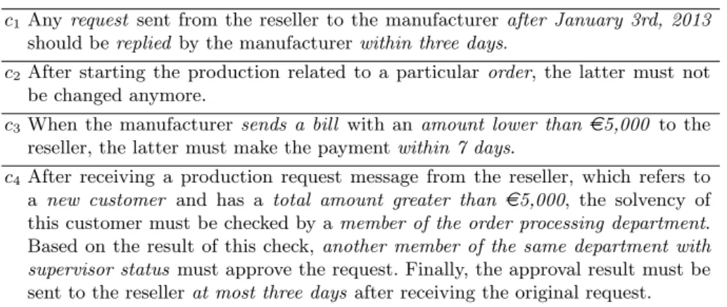
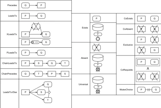
The compliance rule graph (CRG) language [15, 24] allows visually modeling compliance rules whose semantics is defined over event traces. More precisely, a CRG is an acyclic graph consisting of anantecedence pattern as well as at least one relatedconsequence pattern. Both patterns are modeled usingoccurrenceand absence nodes, which indicate the occurrence or absence of events (e.g., related of the execution of a particular task). Edges between such nodes indicate control flow dependencies. As illustrated in Fig. 1, a trace is considered as compliant with a CRG iff for each match of the antecedence pattern there is at least one corresponding match of every consequence pattern. Furthermore, a trace is considered astrivially compliantiff there is no match of the antecedence pattern.
For example, the CRG from Fig. 1 expresses that for each B not preceded by anA, there must occur aD, which is not preceded by anyC also preceding the correspondingB.
C D C D
Antecedence pattern Consequence pattern
only match < E, D, F, G, B >
only match < D, F, C, E, B >
no match ( < A, B, C, E, D > ) only match < C, F, B, G, E >
1st match < B, C, D, E, B >
2nd match< B, C, D, E, B >
< E, D, F, G, B >
< D, F, C, E, B > (C is after D!) -
no match (missing D)
< B, C, D, E, B >
no match ( < B, C, D, E, B > )
A B
A B A B
< E, D, F, G, B >
< D, F, C, E, B >
< A, B, C, E, D >
< C, F, B, G, E >
< B, C, D, E, B >
compliant compliant trivially compliant violation violation
Antecedence Occurrence Antecedence
Absence
Consequence Absence
Consequence Occurrence
CRG
Fig. 1: CRG example and semantics over execution traces
In the following sections, we introduce the extended Compliance Rule Graph (eCRG) language, which is based on CRGs. In addition to using nodes and connectors (i.e., edges), eCRG allows forattachments. The latter represent con- straints to the nodes or edges they are attached to. Furthermore, an eCRG may contain instance nodes representing particular instances, which exist indepen- dently from the respective rule (e.g. a particular employee Mr. Smith, date3rd January 2013, or rolesupervisor). Accordingly, instance nodes are neither part of the antecedence nor the consequence pattern.
3.2 Process Perspective
We first consider the process (i.e., control flow) perspective. The eCRG elements for modeling the process (i.e. control flow) perspective of compliance rules are in- troduced in Fig. 2. Since the extensions are based on the CRG language, there ex- ist four different task elements, i.e.,antecedence occurrence,antecedence absence, consequence occurrence, andconsequence absence tasks. These allow expressing whether or not particular tasks must be executed. In addition, two different kinds of sequence flow connectors are provided that may be used to constrain
Performer
Task Task
Performer
Task Tasks Nodes – Local View
Antecedence Consequence
OccurenceAbsence
Task Task
Task
Tasks Nodes – Interaction View Antecedence Consequence
OccurenceAbsence
Performer
Task Task
Performer
Sequence Exclusion Antecedence Connectors
Sequence Exclusion Consequence Connectors
Alternative
Alternative
Fig. 2: eCRG elements of the process perspective
the execution sequence of tasks. Note that the absence of sequence flow indicates a parallel flow. To clearly distinguish between start-start, start-end, end-start, andend-end constraints on the execution sequence of tasks, sequence flow edges are either connected to the right or left border of a task node. Furthermore, exclusive connectors allow modeling mutual excluding tasks. Alternative con- nectors, in turn, express that at least one of the connected tasks must occur.
Note that exclusive as well as alternative connectors may only connect nodes that are either part of the antecedence or the consequence pattern.
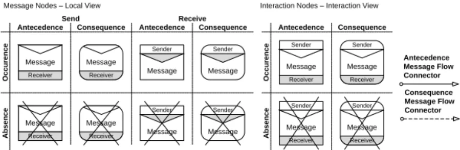
Fig. 4A shows an example of a start-start constraint on the execution sequence of tasks. It depicts the process perspective of compliance rule c2 from Table 1 that disallows executing taskchange order after task production is started.
3.3 Interaction Perspective
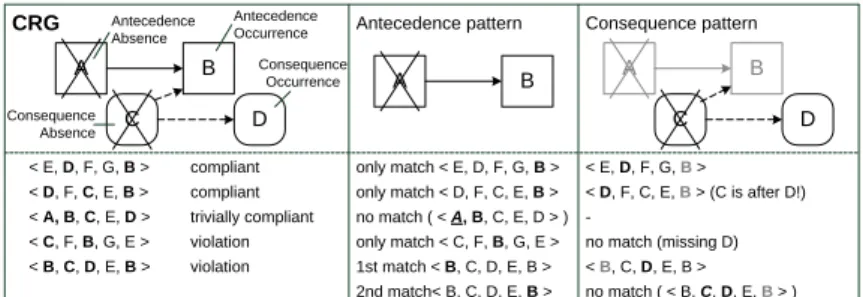
The interaction perspective of business processes is crucial in cross-organizational scenarios [51, 13]. It covers constraints on the messages exchanged between busi- ness pratners and the interaction view of the eCRG meta-model. Message ex- changes are expressed in terms of particular nodes that reflect the events of sending and receiving a message. In turn, a message flow denotes the depen- dency between the events representing the sending and receiving of a particular message (cf. Fig. 3).
Antecedence Consequence Antecedence Consequence
Sender
Message Receiver
Sender
Message Receiver
Sender
Message Receiver
Sender
Message Receiver
Antecedence Consequence
OccurenceAbsence
Antecedence Message Flow Connector Consequence Message Flow Connector Interaction Nodes – Interaction View
Message Nodes – Local View
Sender
Receiver Message
Message
Sender
Message Receiver
Message
Sender
Receiver Message
Message
Sender
Message Receiver
Message
Receive Send
OccurenceAbsence
Fig. 3: eCRG elements of the interaction perspective
Production
Change Order
Reseller
Reseller Reply Check
Solvency Approval
Request
A B
Fig. 4: Local view onc2andc4 with process and interaction perspectives
Reseller
Request Manufacturer
Manufacturer
Reply Reseller
Manufacturer
Billing Information
Reseller
Payment Reseller B
A
Fig. 5: Interaction view onc1andc3 with process and interaction perspectives
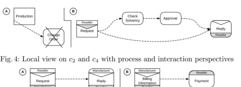
In Fig. 4B, the elements from Fig. 3 are used to model the process and inter- action perspective of compliance rule c4. This rule requires that after receiving messagerequest from a reseller, asolvency check must be performed first. Then, a decision aboutapproval has to be made before replying therequest. Although the rule modeled in Fig. 4B considers the interaction perspective, using the two message nodesrequest andreply, it still represents the view of a particular busi- ness partner on its local business processes. We refer to this traditional point of view as the local view of a compliance rule. However, when considering the compliance rules c1 andc3 from Table 1, one can easily discover a global point of view on cross-organizational processes and related interactions (i.e., the mes- sages exchanged) that corresponds to the BPMN 2.0choreography diagram. In this interaction view, interaction nodes (cf. Fig. 3) are used to denote the ex- change of a message between two business partners. Since the interaction view spans multiple business partners, task nodes may be annotated with the the business partner responsible (cf. Fig. 2).
Fig. 5A provides an interaction view on compliance rulec1 from Table 1: After the reseller sends a request to the manufacturer, eventually, the manufacturer mustreply. Furthermore, Fig. 5B provides an interaction view on compliance rule c3from Table 1. This rule requires that the reseller must perform taskpayment after having receivedbilling information from the manufacturer.
3.4 Time Perspective
The time perspective of a business process deals with temporal constraints that need to be obeyed by instances of the process [28, 29].
Having a closer look on the original definition of compliance rules c1 and c3
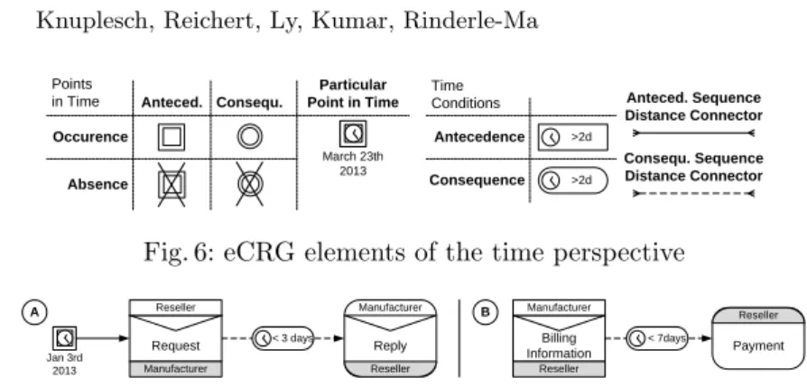
from Table 1, it becomes clear that the eCRGs from Figs. 5A and 5B do not fully specify them yet. In particular, the time distances between the interactions and tasks have not been modeled. Fig. 6 provides elements for modelingpoints in time andtime conditions in compliance rules. The latter may be attached to task nodes as well as sequence or message flow connectors to either constrain the duration of a task or the time distance between tasks, messages or points in time.
Additionally, time distance connectors are introduced that must be attached
Occurence Anteced.
Points in Time
Antecedence Consequence Time Conditions
>2d
>2d
Anteced. Sequence Distance Connector Consequ. Sequence Distance Connector Absence
March 23th 2013 Particular Point in Time Consequ.
Fig. 6: eCRG elements of the time perspective
Reseller
Request Manufacturer
Manufacturer
Reply Reseller
< 3 days Jan 3rd
2013
Manufacturer
Billing Information
Reseller
Payment Reseller
< 7days
A B
Fig. 7: Interaction view onc1andc3 with process, interaction and time perspec- tives
with a time condition. Respective time distance connectors and related time conditions then allow constraining the time distance between tasks, messages or points in time without implying a particular sequence.
Fig. 7A combines the interaction and time perspectives of compliance rule c1. This visual representation ofc1 covers exactly the semantics of the compliance rule described in Table 1. In Fig. 7B, the interaction and time perspectives of c3are provided. This compliance rule requires that at most seven days after the manufacturer sendsbilling information to the reseller, the latter must perform taskpayment.
3.5 Resource Perspective
The resource perspective covers the different kinds of human resources as well as their inter-relations [25, 52]. Further, it allows constraining the assignment of resources to tasks. In the context of our work, we consider resources like staff member,role, group, andorganizational unit as well as their relations to tasks.
Furthermore, we supportresource conditionsandrelationsamong resources (cf.
Fig. 8). Similar to task nodes, resource nodes may be part of the antecedence or consequence patterns. Alternatively, they may represent a particular resource instance (e.g. staff member Mr. Smith, or role supervisor). In turn, resource conditions may constrain resource nodes. Furthermore, theperforming relation indicates the performer of a task. Finally, resource relation connectors express relations between resources. Note that the resource perspective can be easily extended with other kinds of resources if required.
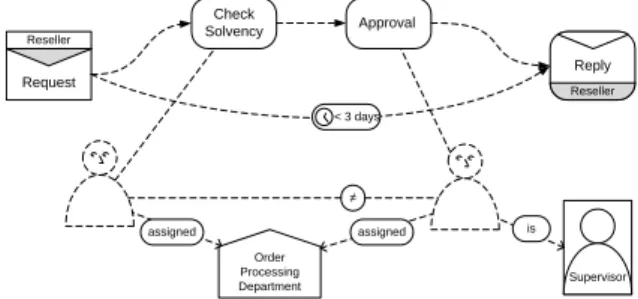
Fig. 9 combines the process, interaction, time, and resource perspectives of com- pliance rulec4. This rule requires that at least three days after receiving arequest of the reseller, a replay must be sent to him. Before sending this reply, first of all, task solvency check must be performed by a staff member assigned to the particular organizational unit order processing department. Following this task, another staff member of the same department withsupervisor status (i.e., role) must decide whether to grant approval before sending thereply.
< value
> value Antecedence Consequence Data/Resource Conditions
Data Object Data Object Data Nodes
AntecedenceConsequence
Antecedence Data Flow Connector Consequence Data Flow Connector
Group Organizational
Unit Staff
Member Role
Group Organizational
Staff Unit
Member Role
Resource Nodes
Antecedence Performing and Relation Connector Consequence Performing and Relation Connector
( )
( ) Data Container
Data Container
Requests Request
from Mrs Ly Particular Resources
Quality Managers
Dept. Information Systems
Mr Knup Computer
Scientist
Fig. 8: eCRG elements of the resource and data perspectives
Supervisor
Reseller
Request
Reseller Reply Check
Solvency Approval
< 3 days
≠
Order Processing Department
assigned is
assigned
Fig. 9: Local view onc4with process, interaction, time, and resource perspectives
3.6 Data Perspective
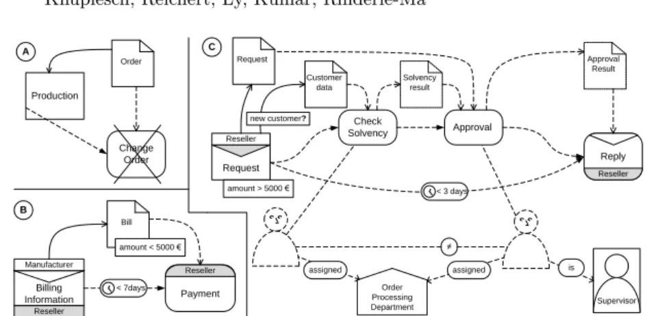
The data perspective of business processes covers the data objects processed as well as the data flow between the tasks of the process [32, 53, 33]. Fig. 8 introduces eCRG elements for modeling data containers and data objects as well as connectors representing data flow. Thereby, data containers refer to process data elements or global data stores. By contrast,data objects refer to particular data values and object instances. Similar to resource nodes,data nodes may be part of the antecedence or consequence pattern, or represent a particular data container or data object (e.g., data containerstudent credit points, document1st order from Mr. Smith). Furthermore,data flow defines which process tasks read or write which data objects or data container. To constrain data container, data objects, and data flow, data conditions may be attached. Finally, data relation connectors may be used either to compare different data objects or to constrain the value of data containers at particular points in time.
Figs. 10A-C show the visual modeling of compliance rulesc2,c3, andc4covering the data perspective as well as the other perspectives discussed. Note that each of the depicted eCRG covers the informal semantics described in Table 1.
Customer data
Supervisor
Reseller
Request Reseller
Reply
amount > 5000 €
Check
Solvency Approval
< 3 days
Request Approval
Result
new customer?
≠
Order Processing Department
assigned Solvency
result
assigned is
Production
Change Order Order
Manufacturer
Billing Information
Reseller
Payment Reseller
< 7days Bill
amount < 5000 € A
B
C
Fig. 10: Local view on c2 and interaction view on c3 and c4, considering the process, interaction, time, resource, and data perspectives
4 Formal Semantics of the eCRG
In the previous section, we have only informally described eCRG semantics. In order to enable automated compliance checking of process logs against eCRG, however, an unambiguous formal semantics is required. For this purpose, this sec- tion provides a transformation from eCRG to first-order predicate logic (FOL), which defines how to interpret and evaluate an eCRG over process logs.
How this transformation can be accomplished is described in the following. First, Section 4.1 introduces sets representing fundamental business process concepts (e.g., tasks types, resources, or data values). Second, process logs are formally defined as set of predicates in Section 4.2. Third, Section 4.3 provides a set-based formal description of an eCRG. Fourth, Section 4.4 defines the transformation translating the eCRG into logic formula based on the defined predicates.
4.1 Environmental Sets and Concepts
The eCRG language relates to different perspectives of business processes, i.e., the process, time, data, resource, and interaction perspectives. The formalization of the eCRG language requires a formal definition of theses fundamental concepts defining theprocess environment in Def. 1 as follows:
Definition 1 (Process Environment).
The environment of a business process comprises the following sets:
– T is the set of task types – Mis set of message types
– Tis the discrete and ordered set of points in time
– R ∶= RS∪ RR∪ RG∪ RU is the set of resources, withRS being the set of staff members, RRbeing the set of roles,RGbeing the set of groups,RU being the set of business units and departments.
– Dset of data containers,P set of activity and message parameters,
– Ωset of data values and objects (e.g.5,1.345, color red, document-A, report-123, . . . ), – IT set of task instance identifiers, and
– IMset of message instance identifier.
Further, based on the definition of the environment, we introduce the following sets of conditions1 and relations for time, data and resources:
– CT⊆ {cont∣cont⊆T→B}is the set of time conditions, – CD⊆ {cond∣cond⊆Ω→B}is the set of data conditions, – CR⊆ {conr∣conr⊆ R →B}is the set of resource conditions, – RT⊆ {relt∣relt⊆T2→B}is the set of time relations, – RD⊆ {reld∣reld⊆Ω2→B}is the set of data relations, and – RR⊆ {relr∣relr⊆ R2→B}is the set of resource relations.
InStaff∈RR is a resource relation and InStaff(r, s)indicates that staff member sbelongs or is assigned to resourcer. Furthermore, we do not explicitly distin- guish between time conditions and time relations, since each time conditioncont
constitutes a time relationrelcont with
relcont(t1, t2) ∶⇔cont(∣t1−t2∣).
4.2 Process Logs
A common way to capture the execution of a business process is to store exe- cution events in process logs and traces [2]. Usually, the latter contain multiple information about the tasks executed, messages exchanged, or data objects ac- cessed. However, not all logged information is of interest for evaluating whether or not a particular process instance complies with a given compliance rule. In- dependent from the concrete format of a process log, we introduce a set of predicates describing its relevant information in Def. 2. Obviously, the values of these predicates can be easily derived by processing a concrete process log:
Definition 2 (Execution Log Entries/Predicates).
LetT,M,T,R,D,IT,IMbe defined as in Def. 1. Then, predicate
– Start(t, i, tt)expresses that taski∈ IT of typett∈ T isstartedatt∈T.
– End(t, i, tt)expresses that taski∈ IT of typett∈ T is completedatt∈T.
– Perform(i, s)expresses that taski∈ IT wasperformedby the staff members∈ RS. – Receive(t, i, mt, b)expresses that messagei∈ IMof typemt∈ Misreceivedfrom business
partnerb∈ Batt∈T.
– Send(t, i, mt, b)expresses that messagei∈ IMof typemt∈ Mis sentto business partner b∈ Batt∈T.
– Parameter(i, p, v)expresses that execution parameterp∈ P of task or messagei∈ IT∪ IM
hasparameter valuev∈Ω.
– Write(t, i, p, v, d) expresses that task or messagei∈ IT ∪ IM writesvaluev∈Ω to data containerd∈ Dvia output parameterp∈ P att∈T.
– Read(t, i, p, v, d) expresses that task or message i∈ IT ∪ IM reads valuev ∈Ω to data containerd∈ Dvia input parameterp∈ Patt∈T.
Based on predicateWrite, we define predicateValue:
Value(t0, o, v) ∶⇔ ∃t1∈T∶t1<t0∧Write(t1,⋅,⋅, v, o) ∧ ∄t2∶t1<t2<t0∧Write(t2,⋅,⋅,⋅, o) Note that we use dots (⋅) as wildcards, i.e.:
Write(t1,⋅,⋅,⋅, o) ⇔ ∃x1, x2, x3∶Write(t1, x1, x2, x3, o)
4.3 Formal Description of eCRG
We now introduce a set-based formal description of the eCRG. Since the latter constitutes a graph, it consists of nodes (e.g. task nodes) and edges (e.g. sequence flow edge). Furthermore, the eCRG nodes and edges may have attachments that specify additional constraints. Thus, we can roughly define an eCRG as specified in Def. 3:
Definition 3 (eCRG).
An eCRGΨ is a graphΨ= (N, E,◇), where
– N is the set of nodes, – Eis the set of edges, and
– ◇is the set of attachments to nodes and edges.
As described in Section 3, each element of an eCRG (i.e., node, edge, or attach- ment) can either be element of the antecedence pattern (A) or theconsequence pattern(C) or be a particularinstance(I) (e.g., a particular employeeMr. Smith, date3rd January 2013, or rolesupervisor). In the cases of nodes, the antecedence pattern is partitioned into theantecedence occurrence pattern(AO) and thean- tecedence absence pattern (AA), while the consequence pattern is partitioned into theconsequence occurrence pattern(CO) and theconsequence absence pat- tern (CA). Before formally introducing these pattern classes in Def. 7, we first define the various elements of an eCRG (i.e., nodes, edges and attachments) in more detail.
Nodes. The most fundamental elements of the eCRG are nodes. According to the different compliance perspectives the set of nodesN can be partitioned into nodes corresponding to tasks, receiving and sending messages, points in time, data containers, data objects, and resources as follows:
Definition 4 (Nodes of an eCRG).
LetN be the set of nodes of an eCRGΨ= (N, E,◇). Then,N can be partitioned as follows:
N∶=T∪MR∪MS∪P∪D∪O∪R, where – T is the set of task nodes,
– MR/MS is the set of receiving/sending message nodes, – Pis the set of nodes representing points in time, – Dis the set of data container nodes,
– Ois the set of data object nodes.
– R∶=RS∪RG∪RR∪RU are the sets of resource nodes for staff members, groups, roles, and organizational units.
In the following, we use TS∪TE instead of T in order to distinguish whether edges are connected to the left and right side of task nodes. Thereby, TS is the left side, i.e. it corresponds to the start of a task, whereas TE is the right side corresponding to completion end of a task. Furthermore, we introduce the function s ∶ T → TS (e ∶ T → TE) to get the start (end) of a task node, and functiont∶TS∪TE →T for the opposite direction. Functiontype∶ (T → T ) ∪ (M → M)assigns to each task and message node the associated task or message
type.bp∶ (MR∪MS) → B denotes the business partner that sends or receives a message. Finally,T M P∶=T∪MR∪MS∪P⊆N is the set of a all task, message, and points in time nodes, whereas DR ∶= D∪O∪R ⊆ N comprises all data container, data object, and resource nodes.
We can partition the set of nodes and each of its subsets into distinct sets of particular instance nodes, antecedence nodes, and absence nodes as well as into particular instance nodes, antecedence occurrence nodes, antecedence absence nodes, consequence occurrence nodes, and consequence absence nodes. We use the exponentsI,A,C,AO,AA,CO andCAto indicate the corresponding subset.
Further, the exponent−I denotes that all nodes are considered except particular instance ones.
Edges. The nodes of an eCRG can be connected through a wide range of edges indicating relations and correlations between these nodes. In particular, the set of edges can be partitioned into distinct subsets (cf. Def. 5). The latter contain edges for sequence flow, message flow, and distance in time. Other edge subsets refer to read/write data flow from/to data containers or data objects as well as to the performers of tasks and relations among data objects or resources. Finally, the two last subsets contain edges specifying correlations between conditions to data containers and the particular points in time, when these conditions are evaluated:
Definition 5 (Edges of an eCRG).
We consider Eas the set of edges of an eCRGΨ = (N, E,◇). Then,E can be partitioned as follows:
E∶=sf#»∪mf# »∪tde# »∪wdf c# »∪rdf c# »∪wdf o# »∪rdf o# »∪pf m# »∪rr#»∪dr#»∪dcec# »∪dceo, where# »
– sf#»⊆ (TS∪TE∪MS∪MR∪P)2×RT is the set of sequence flow edges including a time condition,
– mf# »⊆MS×MRis the set of message flow edges,
– tde# »⊆ (T∪MR∪MS∪P)2×CT is the set of time distance edges including a time condition, – wdf c# »⊆ (T∪MR∪MS)×(P ∪{⋅})×Dis the set of data flow edges writing to a data container, – rdf c# »⊆D× (T∪MR∪MS) × (P ∪ {⋅}) is the set of data flow edges reading from a data
container,
– wdf o# »⊆ (T∪MR∪MS) × (P ∪ {⋅}) ×Ois the set of data flow edges writing a data object, – rdf o# »⊆O× (T∪MR∪MS) × (P ∪ {⋅})is the set of data flow edges reading a data object, – pf m# »⊆T×Ris the set of performing relation edges denoting the performer of a task, – rr#»⊆R2×RRis the set of resource relation edges,
– dr#»⊆O×O×RD is the set of data relation edges,
– dcec# »⊆ (TS∪TE∪MR∪MS∪P) ×D×CD is the set of data condition edges constraining a data container at a particular point in time by a data condition,
– dceo# »⊆ (TS∪TE∪MR∪MS∪P) ×D×Ois the set of data condition edges requiring a data container to contain a data object at a particular point in time.
Further, src∶ E → N (tgt ∶ E → N) is a function that maps each edge to its source node (target node), whereas nd∶E →N, e↦nd(e) ∶= {src(e), tgt(e)} is a function that maps each edge to the set containing its source and target node.
Edges are either part of the antecedence or the consequence pattern. Hence, we can further partition the set of edges and each of its subsets into antecedence and
consequence edges. We use exponentsAandC to indicate when only considering the particular subset.
According to the definition of # »
sf, each sequence flow requires a time relation.
Thereby, if the graphical representation does not provide a time relation, we just assume the time condition to be T2, i.e., true for each input. Further an antecedence edge with a consequence time condition is interpreted as two edges:
an antecedence edge without a time condition and a consequence edge with the respective time condition.
Attachments. Nodes and edges of an eCRG may be refined by attachments. In turn, these attachments constitute additional conditions for the respective node or edge. In particular, the set of attachments
◇
can be partitioned into distinct subsets. The latter refer to different data conditions constraining data flow or parameters of tasks or messages. Other attachments express time conditions that constrain the duration of tasks or resource conditions that constrain resources:Definition 6 (Attachments of an eCRG).
We consider◇as the set of attachments of an eCRGΨ= (N, E,◇). Then,◇can be partitioned as follows:
◇∶=◇dcp∪◇doc∪◇df c∪◇df o∪◇td∪◇rc, where
– ◇dcp⊆ (T∪M)×P×CDattaches a task or message node with a data condition on a particular parameter,
– ◇doc⊆O×CD attaches data object nodes with a data condition,
– ◇df c⊆ (wdf c# »∪rdf c# »∪wdf o# »∪rdf o# ») ×CD attaches data flow edges with a data condition, – ◇df o⊆ (wdf c# »∪rdf c# »)×Oattaches data flow edges from/to a data container with a data object
serving as placeholder for the value of the data flow,
– ◇td∶T×RT attaches task nodes with a time relation that constraints the duration of the task, and
– ◇rc∶R×CRattaches resource nodes with a resource condition.
Further, at∶
◇
→N∪E is a function mapping each attachment to the node or edge it corresponds to. Attachments are either part of the antecedence or the consequence pattern. Consequently, we can partition the set of attachments and each of its subsets into antecedence and consequence attachments. Again, we use exponentsA andC when solely referring to the respective subset.Pattern Classes. As mentioned in Section 3, nodes, edges, and attachments can be classified as elements of the instance, the antecedence, or the consequence pattern. In the context of nodes, the antecedence and consequence pattern are further partitioned into the antecedence occurrence and the antecedence absence pattern as well as the consequence occurrence and the consequence absence pat- tern. Def. 7 formally introduces the pattern classes and transfers the finer classi- fication to edges and attachments (i.e., the classification into antecedence occur- rence, antecedence absence, consequence occurrence, and consequence absence patterns). For this purpose, we consider pattern classes of the nodes connected by an edge as well as the pattern class of the element an attachment corresponds to.
Definition 7 (Classes of an eCRG).
LetΨ= (N, E,◇)be an eCRG. Then:
– I∶=NIis the instance pattern,
– A∶=NAO∪NAA∪EA∪◇Ais the antecedence pattern, – C∶=NCO∪NCA∪EC∪◇C is the consequence pattern,
– EAO∶= {e∈EA∣nd(e) ⊆NAO}is the set of antecedence occurrence edges,
– EAA∶= {e∈EA∣nd(e) ∩NAA≠ ∅ ∧nd(e) ∩NAO≠ ∅}is the set of antecedence absence edges, – ECO∶= {e∈EC∣nd(e)∩NC≠ ∅∧nd(e) ⊆ (NCO∪NAO)}is the set of consequence occurrence
edges,
– ECA∶= {e∈EC∣nd(e) ∩NCA≠ ∅ ∧ nd(e) ∩ (NCO∪NAO) ≠ ∅}is the set of consequence absence edges,
– ◇AO∶= {a∈◇A∣at(a) ∈NAO∪EAO}is the set of antecedence occurrence attachments, – ◇AA∶= {a∈◇A∣at(a) ∈NAA∪EAA}is the set of antecedence absence attachments, – ◇CO∶= {a∈◇C∣at(a) ∈NAO∪EAO∪NCO∪ECO}is the set of consequence occurrence
attachments,
– ◇CA∶= {a∈◇C∣at(a) ∈NCA∪ECA}is the set of consequence absence attachments, – AO∶=NAO∪EAO∪◇AOis the antecedence occurrence pattern,
– AA∶=NAA∪EAA∪◇AA is the antecedence absence pattern, – CO∶=NCO∪ECO∪◇COis the consequence occurrence pattern, – CA∶=NCA∪ECA∪◇CAis the consequence absence pattern, and – C ∶= {I, AO, AA, CO, CA}is the set of pattern classes.
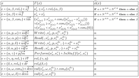
4.4 Transformation of eCRG
After having defined a formal representation of the process environment, process logs and compliance rules, we are able to define the semantics of a particular compliance rule. For this purpose, we transform the eCRG into a first-order pred- icate logic formula in this subsection. Instead of nodes, edges and attachments, the resulting logic formula comprises variables derived from the eCRG elements.
However, note that the set of variables is not isomorphic to the sets of nodes and edges. Thus, Def. 8 introduces the variables required, before describing the transformation in detail. In this context, we use relation ∈ to indicate the set of values a variable may take.
Definition 8 (Variables).
LetΨ= (N, E,◇)be an eCRG, then:
– νtx∈Tcorresponds for eachx∈TS∪TE∪MR∪MS∪Pto the variable for either the point in time of the start (end)xof a task node, the point of receiving (sending) a message related to message nodex, the time related to a point in time nodex, or the particular point in time ofxiffx∈PI is a particular point in time instance node.
– νix∈ IT∪ IMcorresponds for eachx∈T∪MR∪MS to the the variable for the instance identifier of a task or message nodex.
– νpx ∈ RS corresponds for eachx∈T to the variable for the performing staff member of a task nodex.