Compliance Rule Graph Language
David Knuplesch and Manfred Reichert Institute of Databases and Information Systems,
Ulm University, Germany
david.knuplesch@uni-ulm.de manfred.reichert@uni-ulm.de
Abstract
A challenge for any enterprise is to ensure conformance of its business processes with im- posed compliance rules. Usually, the latter may constrain multiple perspectives of a business process, including control flow, data, time, resources, and interactions with business part- ners. Like for process modeling, intuitive visual languages have been proposed for specifying compliance rules. However, business process compliance cannot completely be decided at design time, but needs to be monitored during run time as well. In previous work we in- troduced the extended Compliance Rule Graph (eCRG) language that enables the visual monitoring of business process compliance regarding the control flow, data, time, and re- source perspectives as well as the interactions a process has with business partners. This technical report introduces an operational semantics of the eCRG language. In particular, the state of a visual compliance rule is reflected through markings and annotations of an eCRG. The proposed operational semantics not only allows detecting compliance violations at run-time, but visually highlights their causes as well. Finally, it allows providing recom- mendations to users in order to proactively ensure for a compliant continuation of a running business process.
This work was done within the research project C3Pro funded by the German Research Foun- dation (DFG) under project number RE 1402/2-1.
1 Introduction
The correctness of business process models has been intensively discussed in literature for more than a decade [1–3]. While earlier work focused on syntactical correctness and sound- ness constraints (e.g., absence of deadlocks and lifelocks), the compliance of business pro- cesses with semantic constraints has been increasingly considered during the last years [4, 5].
Usually,compliance rules stem from domain-specific constraints, e.g., referring to corporate standards, legal regulations or evidenced best practices [6, 7] , and need to be ensured in all phases of the process life cycle [8, 9].
Approaches dealing with the compliance of business processes during their execution are covered by the notion of compliance monitoring. In order to detect and report run-time violations of compliance rules, events of running business process instances need to be con- sidered (cf. Fig. 1). Note that two kinds of monitoring need to be distinguished: reactive and proactive monitoring. Regarding reactive monitoring, the process-aware information system only reports a compliance violation once it has occurred. In turn, proactive moni- toring aims to proactively prevent potential compliance violations that might occur during the further course of process execution; e.g. by suggesting appropriate tasks that still need to be executed to meet the compliance rule.
WfMS System CRM
System
ERP System ...
Single Client
...
Compliance Monitoring
Event Bus Compliance
Rules
Compliance Reporting
Fig. 1: Compliance monitoring [10, 5]
A multitude of approaches focusing on compliance monitoring at run-time were intro- duced during the last years [11–13]. While early suggestions focused on the control flow perspective, later proposals for monitoring compliance considered additional process per- spectives as well [14, 15]. In particular, the data, resource, and time perspectives have been addressed. Other approaches, in turn, have focused on the traceability of compliance vio- lations [10, 16]. Furthermore, [5] proposed 10 fundamentalcompliance monitoring function- alities (CMFs) that may be used to compare existing approaches for monitoring business process compliance. In this context, the authors stated that existing approaches do not provide a satisfactory solution that combines an expressive language with full traceability capabilities [5].
To close this gap, this report introduces an operational semantics for the extended Com- pliance Rule Graph (eCRG) language. The latter has been introduced in [17, 18] and enables
the visual monitoring of business process compliance. In particular, the operational seman- tics annotates eCRGs with text, colors and symbols. In order to deal with compliance rules, which are triggered multiple times during the execution of a business process instance, the operational semantic creates and annotates multiple instances of an eCRG in parallel. The annotated instances of an eCRG not only indicate compliance violations, but may be also utilized for recommending the next process steps (i.e. activities), whose execution will en- sure compliance. Furthermore, they provide a suitable basis for compliance metrics. Note that the eCRG language is a powerful visual notation for compliance rules that adequately supports the control flow, data, time, and resource perspectives as well as interactions with business partners. Consequently, this report not only provides the operational basis for mon- itoring control flow constraints, but enables the monitoring of the latter perspectives as well.
Altogether the provided operational semantics provides the basis for
– utilizing the eCRG language for monitoring business process compliance during process execution.
– monitoring the conformance with compliance rules related to any process perspective;
i.e., the control flow, data, time, resource perspectives as well as the interactions a process has with business partners.
– dealing with compliance rules, which are are triggered multiple times.
– reasoning about the violation of compliance rules – reactively & proactively.
– specifying compliance metrics and measures.
The remainder of this report is structured as follows: Section 2 discusses related work.
Section 3 provides a motivating example. Backgrounds on the extended Compliance Rule Graph (eCRG) language are introduced in Section 4. Section 5 provides an operational semantics for the eCRG language. In particular this operational semantics formally specifies the transitions between the states of compliance rules. In turn, Section 6 evaluates and classifies the compliance of an eCRG. Furthermore, the specification of compliance metrics and measures is introduced as well as the provision of recommendations to users. Finally, Section 7 concludes the paper and provides an outlook on future research.
2 Related Work
For a decade, business process compliance has increasingly gained attention and several sur- veys have been published in the meantime (e.g., [19, 8, 20, 21, 5]). Along this trend, interest incompliance monitoring andcontinous auditing [12] has grown as well. For example, [11]
enriches process models with a semantic layer of internal controls. In [13, 22], in turn, the detailed architectures of an online auditing tools (OLAT) are described. An OLAT allows monitoring the operations of an organization in detective, corrective and preventive modes.
The spectrum of techniques applied for compliance monitoring is wide spread:Behavioural profiles [23] utilize ordering relations in this context, whereasSupeverisory Control Theory [24] prevents users from performing actions leading to compliance violations. Furthermore, visual declarative constraints [25], which are transformed intoEvent Calculus and Linear Temporal Logic(LTL), have shown increasing popularity.Fuzzy conformance checking [26]
calculates an evaluation score that indicates how much the observed process instance com- plies instead of providing a simpleyes/no answer.
In order to enable fine-grained compliance diagnostics at run-time, Compliance Rule Graphs[10] and colored automata [16] have been suggested. However, both mainly focus on control flow perspective. In turn, [5] compares approaches for monitoring business process compliance based on 10 compliance monitoring functionalities (CMF). In particular, it is emphasized that existing approaches do not provide a satisfactorily solution that combines an expressive language (CMF 1-5) with full compliance traceability (CMF 8+9). Table 1 summarizes the results from [5].
Table 1: Compliance monitoring functionalities [5]
CMF 1 CMF 2 CMF 3 CMF 4 CMF 5 CMF 6 CMF 7 CMF 8 CMF 9 CMF 10 time data resources non life- multi- reactive proactive root compl.
Approach atomic cycle instance mgmt mgmt cause degree
Mubicon LTL [16] +/- - - + - - + + + +/-
Mubicon EC [25, 15] + +/- + + + + + - +/- +/-
ECE Rules [26] + +/- + + - - + - +/- +
SCT [24] +/- - + + + - - + - -
SeaFlows [10] +/- +/- +/- + +/- + + + + +/-
As opposed to the approaches described above, [27] monitors performance measures in the context of artifact-centric process models. In turn, [28, 14, 29] provide techniques toa posteriori verify the compliance of execution logs with a set of constraints. Some of these approaches not only focus on the control flow perspective, but take the time perspective [14]
or resource perspective [28] into account as well.
A priori or design time compliance checking has been addressed by a multitude of ap- proaches for a long time. Most of them apply model checking techniques (e.g., [30–33]). In addition, some of these design time approaches use visual compliance rules and not only consider the control flow perspective, but the data, interaction or time perspectives as well.
Other compliance checking approaches, in turn, are based on Petri-Nets [34] and Mixed- Integer Programming [35].
Finally, there are few frameworks, which address the integration of business process compliance throughout the entire process lifecycle [9, 36, 8, 37, 38].
3 Motivating Example
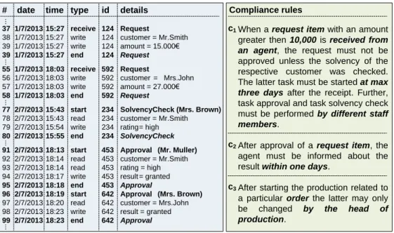
This section introduces a motivating example, which refers to the event log from Fig. 2 and deals with an order-to-delivery process. The latter is subject to three compliance rules, which stem from internal guidelines.
Note that compliance rulec1 is satisfied in one case, but violated in another. In partic- ular, the depicted log refers to two different request items related to customersMr. Smith andMrs. John. These items, in turn, trigger two different instances of compliance rulec1. In both cases, the amount is greater than 10,000eand hence a solvency check is required.
However, the latter was only performed for the request item of Mr. Smith, but not for the one ofMrs. John (i.e.,c1is violated in the latter case). Besides the violation ofc1, compli- ance rulec2 is violated twice as well. While the violated instance of rulec1 will never be successfully completed, the violations ofc2 still may be healed by informing theagent, who sent the requests, about the results of the approvals.
The compliance rule examples further indicate that solely monitoring control flow de- pendencies between tasks is not sufficient in order to ensure compliance at run-time. In addition, constraints in respect to the data, time and resource perspectives of a business process as well as the interactions this process has with partner processes must be moni- tored [39, 21, 17, 18]. For example, the data perspective of compliance rulec1 is addressed by the request item and itsamount. In turn, receiving the request item (cf. c1) represents an interaction with a business partner. The phrase ”by different staff members” deals with the resource perspective, whereas the condition ”at max three days” refers to the time per- spective. To meet practical demand, compliance monitoring must not abstract from these process perspectives.
# date time type id details 37 1/7/2013 15:27 receive 124 Request
38 1/7/2013 15:27 write 124 customer = Mr.Smith 39 1/7/2013 15:27 write 124 amount = 15.000€
39 1/7/2013 15:27 end 124 Request 55 1/7/2013 18:03 receive 592 Request
56 1/7/2013 18:03 write 592 customer = Mrs.John 57 1/7/2013 18:03 write 592 amount = 27.000€
58 1/7/2013 18:03 end 592 Request
77 2/7/2013 15:43 start 234 SolvencyCheck (Mrs. Brown) 78 2/7/2013 15:43 read 234 customer = Mr.Smith 79 2/7/2013 15:54 write 234 rating= high 80 2/7/2013 15:55 end 234 SolvencyCheck 91 2/7/2013 18:13 start 453 Approval (Mr. Muller) 92 2/7/2013 18:14 read 453 customer = Mr.Smith 93 2/7/2013 18:14 read 453 rating = high 94 2/7/2013 18:17 write 453 result = granted 95 2/7/2013 18:18 end 453 Approval
96 2/7/2013 18:19 start 642 Approval (Mrs. Brown) 97 2/7/2013 18:20 read 642 customer = Mrs.John 98 2/7/2013 18:23 write 642 result = granted 99 2/7/2013 18:23 end 642 Approval
When a request item with an amount greater then 10,000 is received from an agent, the request must not be approved unless the solvency of the respective customer was checked.
The latter task must be started at max three days after the receipt. Further, task approval and task solvency check must be performed by different staff members.
After approval of a request item, the agent must be informed about the result within one days.
After starting the production related to a particular order the latter may only be changed by the head of production.
c1
c2
c3
Compliance rules
...............
Fig. 2: Event log of order-to-delivery processes and compliance rules
4 Fundamentals of Extended Compliance Rule Graphs
This paper utilizes the extended Compliance Rule Graph (eCRG) language for compliance monitoring. Since this language is based on the Compliance Rule Graph (CRG) language, we first introduce CRGs before presenting eCRG fundamentals.
4.1 Compliance Rule Graphs
The Compliance Rule Graph (CRG) language was introduced in [40, 10, 41]. It allows for the visual modeling of compliance rules that focus on the control flow perspective (i.e., sequence flow) of business processes. A CRG corresponds to an acyclic graph that consists of an antecedence pattern as well as one or multiple related consequence patterns. Both kinds of patterns are modeled usingoccurrenceandabsence nodes, which either express the occurrence or absence of events (e.g. events related to the execution of a particular task).
Furthermore, the edges connecting these nodes express control flow dependencies.
As illustrated in Fig. 3, an event trace (i.e., a finite sequence of events related to the same process instance) is considered as compliant with a CRG iff for each match of the antecedence pattern there is at least one corresponding match for one of the consequence pattern. In turn, a trace is considered as trivially compliant iff there is no match of the antecedence pattern at all. As example consider the CRG from Fig. 3. It expresses that for each B not preceded by an A, a D must occur. Further, there must be no C that precedes B and D.
C D C D
Antecedence pattern Consequence pattern
only match < E, D, F, G, B >
only match < D, F, C, E, B >
no match (A is before B) only match < C, F, B, G, E >
1st match < B, C, D, E, B >
2nd match < B, C, D, E, B >
< E, D, F, G, B >
< D, F, C, E, B > (C is after D) -
no match (missing D)
< B, C, D, E, B >
no match (C is before B and D)
A B
A B A B
< E, D, F, G, B >
< D, F, C, E, B >
< A, B, C, E, D >
< C, F, B, G, E >
< B, C, D, E, B >
compliant compliant trivially compliant violation violation Antecedence Occurrence Antecedence
Absence
Consequence Absence
Consequence Occurrence
CRG
Traces
Fig. 3: CRG example and semantics [8]
4.2 Extended Compliance Rule Graph
The CRG language focuses on thecontrol flow perspective of compliance rules, but ignores other perspectives. In [17, 18], therefore, we introduced the extended Compliance Rule Graph (eCRG) as a visual language for modeling compliance rules not only covering the control flow perspective, but providing integrated support for the resource, data and time perspectives as well as for interactions with business partners. To cover these various perspectives, the eCRG language allows forattachments in addition to nodes andconnectors (i.e. edges). Thereby, nodes refer to entities (e.g. a data object) or events, whereas edges and attachments are used to refine the nodes or edges they are affiliated to. Furthermore, an eCRG may contain instance nodesreferring to particular objects, which exist independently from the respective rule (e.g.Mr. Smith, postnatal ward, physician). Hence, instance nodes are neither part of
the antecedence nor the consequence pattern, but constitute theinstance patter. Fig. 4 gives an overview of the elements of the eCRG language.
OccurenceAbsence
Antecedence Consequence
Task
Task Task
Task
Data Object Data Object Data Nodes
AntecedenceConsequence
Group Organizational
Staff Unit
Member Role
Group Organizational
Staff Unit
Member Role
Resource Nodes
Requests Request Particular Data Nodes
Quality Managers
Radiology Department Computer
Scientist Mr X
Antecedence
Consequence Time Conditions
>2d >2d March 23th
2013 Point in Time Extended Compliance Rule Graph Language (eCRG)
Process Perspective Time Perspective
Resource Perspective Data Perspective
< value
> value Antecedence Consequence
Data Conditions
AntecedenceConsequenceParticular Resources
Antecedence Consequence Antecedence Consequence
Sender
Receiver Message
Message
Sender Message Receiver
Message
Sender
Receiver Message
Message
Sender Message Receiver
Message
Receive Send
OccurenceAbsence
Interaction Perspective
Sequence Exclusion Antecedence
Alternative Basic Connectors
Sequence Exclusion Consequence
Alternative
property property Antecedence Consequence
Resource Conditions
Data Container
Data Container Resource Connectors
Time Nodes
Performing Relation Antecedence
assigned to
Performing Relation Consequence
assigned to
Data Connectors
Data Flow Antecedence
Data Flow Consequence
Knuplesch, Reichert, Ly, Kumar, Rinderle- Ma: Visual Modeling of Business Process Compliance Rules with the Support of Multiple Perspectives. In: ER 2013, LNCS, Springer (2013), pp. 106-120
Fig. 4: Elements of the eCRG language [17, 18]
The elements of the eCRG language are partitioned into the control flow, data, time, resource and interaction perspectives that will be described in the following in more detail (cf. Fig. 4).
Control flow perspective.Modeling the control flow perspective of compliance rules is supported through four kinds of task nodes, i.e., antecedence occurrence, antecedence ab- sence, consequence occurrence, and consequence absence task nodes. Based on these nodes it can be expressed whether or not particular tasks shall be executed. In addition, two kinds ofsequence flow connectors are provided that allow constraining the execution sequence of tasks. Note that the absence of a sequence flow indicates parallel flow. Furthermore, ex- clusive connectors express mutual exclusion of the tasks they refer to. Finally, alternative connectorsexpress that at least one of the connected tasks must occur.
Interaction perspective.The interaction perspective supports the exchange of messages with business partners. According to task nodes, four kinds of sending and four kinds of receiving message nodes are provided, i.e., antecedence occurrence, antecedence absence, consequence occurrence, and consequence absence nodes.
Time perspective.The eCRG language offers the following elements for modeling the time perspective:Point-in-time nodes,time condition attachments, andtime distance connectors.
Point-in-time nodes express a particular date or point-in-time (e.g. 26th October 2014).
Time conditions, in turn, may be attached to task nodes and sequence flow connectors to constrain the duration of a task or the time distance betweentask nodes,message nodes and point-in-time nodes. Finally,time distance connectors allow constraining the time distance without implying a particular sequence.
Data perspective.Data container nodes anddata object nodes support the modeling of the data perspective in eCRGs. Furthermore,data flow connectors,data relation connectors and data condition attachments are provided. Data container nodes refer to process data elements or global data stores. By contrast,data object nodes refer to particular data values and data object instances. Both kinds of data nodes may be part of the antecedence or consequence pattern, or represent a particular data container and data object, respectively.
Data flow connectors define which process tasks read or write which data objects or data containers. To constrain data containers, data objects and data flow,data conditions may be attached. In turn,data relation connectors allow comparing data objects.
Resource perspective.For modeling the resource perspective of compliance rules,resource nodesare provided, i.e.,staff member,role,group, andorganizational unit nodes. Similar to task nodes,resource nodes may be part of the antecedence or consequence pattern. Alter- natively, they may represent a particular resource instance (e.g.Mr. Smith, postnatal ward, physician). To specify dependencies among resources,resource relation connectors are pro- vided. In turn,resource condition attachmentsconstrain a particular resource node. Finally, theperforming relation indicates the performer of a task node.
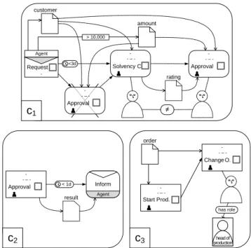
Fig. 5 applies the eCRG language in order to model the compliance rules from our motivating example in Section 3, which have been presented in verbalized form in Fig. 2.
In particular, Fig. 2(c1)addresses all process perspectives, i.e., the control flow, data, time and resource perspectives as well as interactions with business partners. In turn, Fig. 2(c2) does not refer to the resource perspective, whereas time and interaction perspectives are not addressed in Fig. 2(c3).
Agent
rating
≠ Request
Approval - - – -
Approval - - – - Solvency C.
- - – - -
c1 customer
amount
> 10,000
Agent Inform Approval
- - – -
< 1d result
c2
Change O.
- - – -
Start Prod.
- - – -
head of production
c3
has role order
<3d
Fig. 5: Modeling compliance rulesc1−3with the eCRG language
A formal specification of an eCRG is provided in Def. 1 (for a more detailed definition of eCRGs including a formal definition ofφsee [42]).
Definition 1 (Extended Compliance Rule Graph (eCRG)).
Let T be the set of points in time, R be the set of human resources, and Ω be the set of all data objects. Then: An extended Compliance Rule Graph (eCRG) is a tuple Ψ= (N, E,◇, type, src, tgt, at, pt)with
– N∶=T ∪MN ∪O∪C∪R∪P being the set of nodesthat may be partitioned into the sets of task nodesT,message nodesMN,data object nodesO,data container nodesC,resource nodesR, and point-in-time nodes P⊂T.
– E∶=sf# » ∪df#»∪ pf m# »∪ rr#» being the set of edges that may be partitioned into the sets of sequence flow edgessf# »,data flow edgesdf,#» performing relationspf m, and# » resource relationsrr.#»
– ◇ ∶=◇dc∪◇tc∪◇rrbeing the set of attachmentsthat may be partitioned into the sets of data conditions◇dc,time conditions◇tc, and resource conditions◇rc, – type∶T ∪MN ∪ #»
df→ T mapping each task node (message node, data flow edge) to a task type(message type,parameter name),
– src∶E→N (tgt∶E→N) mapping each edge to its source(target) node,
– at ∶ ◇ → N ∪ E mapping each attachment to the underlying node or edge it is attached to, and
– pt ∶ N ∪ E ∪ ◇ → {AO, AA, CO, CA, I} mapping each element of an eCRG to the corresponding pattern.
Further:
– ΛΨ ∶=N ∪ E ∪ ◇is the set of all elements,
– ΓΨ ∶=T ∪ MN is the set of task and message nodes,
– φΦ ∶ ΛΨ → ΛΨ maps each element to its affiliation; i.e., the element to which it is affiliated3.
– For each set X ⊂ ΛΨ of elements of an eCRG and each pattern y ∈ {AO, AA, CO, CA, I}, we define Xy ∶= {x ∈ X∣pt(x) = y} as the pattern y of X.
AO
AA
CA CO
I
Fig. 6: Dependencies of eCRG pattern
Functionptpartitions the elements of an eCRG in five patterns, which are the instance pattern (I) as well as the antecedence occurrence (AO), antecedence absence (AA), con- sequence occurrence (CO), and consequence absence (CA) patterns. Dependencies among these patterns are shown in Fig. 6, whereas the lower ones depend on the upper ones they
are connected to. Based on the latter, Def. 2 formally specifies how connected elements con- strain and depend on each other. In particular, a node, edge or attachmentλ1 depends on another elementλ2, if they are connected and the pattern ofλ1 depends on the one ofλ2. For example, task nodeproductiondepends on its outgoing sequence flow edge in Fig. 5(c3).
In turn, in Fig. 5(c3), message node request does not depend on both outgoing sequence flows. Instead, the latter depend on the message node.
Definition 2 (Pattern Dependency Order).
Let Ψ = (N, E,◇, type, src, tgt, at, pt) be an eCRG and let λ1, λ2 ∈ ΛΨ be two elements of the eCRG. Then:
– ▸ defines the partial dependency order over the set of patterns as specified in Fig. 6 (e.g.I▸AA),
– We sayλ1 has a higher dependency level thanλ(i.e., λ1▷λ2), iff the pattern ofλ1 is greater than the one ofλ2 according to the dependency order▸, i.e.,
λ1▷λ2∶⇔pat(λ1) ▸pat(λ2) – and⊵,≜,◁ and⊴are defined accordingly.
5 eCRG Operational Semantics
This section introduces the operational semantics of the eCRG language that enables visually monitoring business process compliance at run-time. As discussed in Section 1, the latter is based on event streams that occur during the execution of business processes. In particular, compliance monitoring shall detect or, if possible, prevent compliance violations. For this purpose, first of all, Section 5.1 introduces the different events that are supported. Second, the fundamental states of a compliance rule are introduced in Section 5.2. Third, Section 5.3 specifies markings that annotate the elements of an eCRG with text, colors and symbols.
Finally, Section 5.4 specifies the processing of events and discusses how the latter evolve and unfold markings of an eCRG (cf. Section 5.4).
5.1 Events
As this report addresses compliance monitoring in respect to multiple process perspectives, we not only monitor events that refer to the start and end of tasks. In addition, we consider events that correspond to the sending and receiving of messages as well as data flow events that log how activities read from and write to data sources. Furthermore, events may include temporal information as well as information about involved resources.
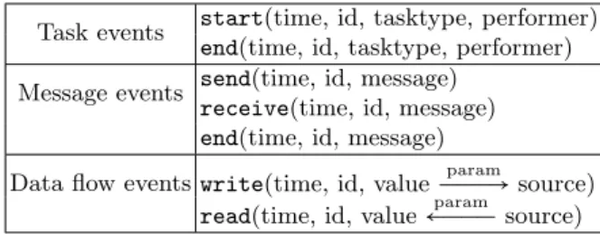
Table 2 summarizes the event types supported by our approach. Note that each event includes the time it occurs as well as a unique id. The latter enables us to identify correlations between the start, end and data flow events related to the same task or message.
Table 2: Supported Events
Task events start(time, id, tasktype, performer) end(time, id, tasktype, performer) Message events send(time, id, message)
receive(time, id, message) end(time, id, message)
Data flow events write(time, id, valueÐÐÐ→param source) read(time, id, value←ÐÐÐparam source)
Based on the events from Table 2, Def. 3 formally specifies event logs and streams.
Definition 3 (Event Log or Event Stream).
LetE be the set of events (cf. Table 2) and letTbe the discrete set of points in time. Then:
– L ∶N→ E ∪ {∅} is an event stream or event log,
– time∶ E →T∶time(event(ϑ, . . .)) ∶=ϑmaps each event to the corresponding point- in-time.
Note that we assume that event streams are correct; i.e., they do not deviate (cf. [43]) from the real process, ids are unique, and events are provided in an ascending order (i.e.,
∀i, j∈ [1..posL] ∶i<j⇒time(L(i)) ≤time(L(j))).
5.2 States of Compliance Rules
When monitoring the compliance of running process instances, compliance rules take vary- ing states [10, 8]. Fig. 7 outlines the states that are supported by our approach. The most
fundamental state isNot Activated, i.e., the compliance rule does not concern the run- ning process instances until now. The opposite stateActivatedmeans that the compliance rule affects the process instance and includes the sub-states TempSatisfied and Tem- pViolated.TempSatisfiedis further partitioned intoViolableandSatisfied, whereas TempViolatedincludes the sub-statesPendingandViolated. As explained by our mo- tivating example in Section 3, business process can multiply trigger (i.e. activate) compliance rule. Hence, a compliance rule can be in state Activated multiple times as indicated by superscript ”+”. Note that each of theseactivations of a compliance rule can take a different sub-state. For instance, the event log of our motivating example activates compliance rulec1 twice (cf. Fig. 2). The first activation isSatisfied, whereas the second activation remains in stateViolated.
ACTIVATED
TEMPVIOLATED (non-compliance) TEMPSATISFIED
(compliance)
VIOLABLE
SATISFIED
PENDING
VIOLATED NOT_ACTIVATED
(trivial compliance)
+
Fig. 7: States of compliance rules
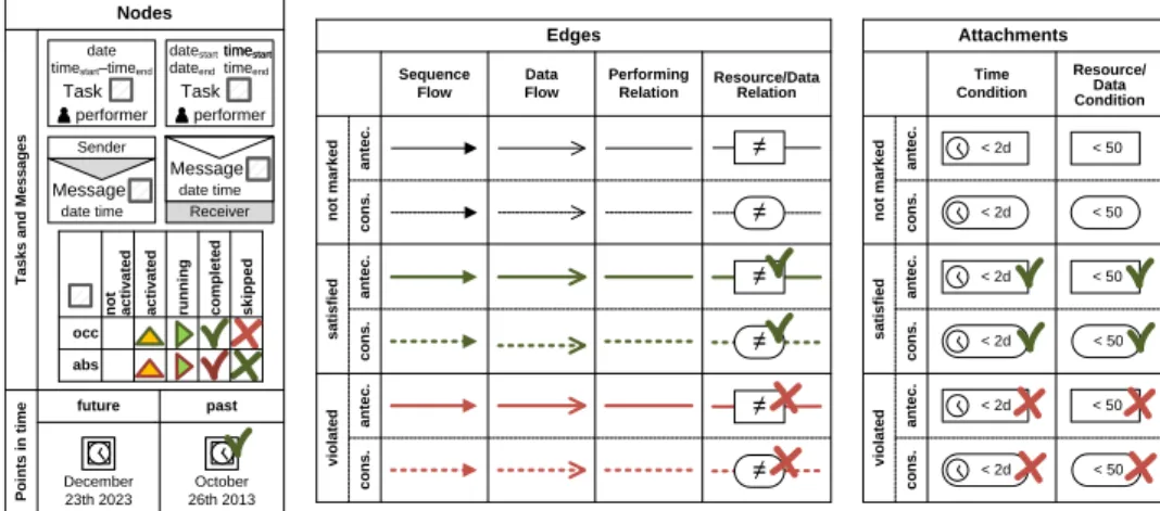
5.3 eCRG Markings
To monitor the state of a compliance rule, we annotate and mark the elements of an eCRG (cf. Section 4, [17, 18]) with symbols, colors and text (cf. Figs. 8). Such amarking of an eCRG(i.e., annotated eCRG) highlights whether or not the events corresponding to a node have occurred so far. Further, it describes whether conditions corresponding to edges and attachments are satisfied, violated, or still will be evaluated (cf. Figs. 8). Since there may be different activations and instantiations of a particular compliance rule, Def. 4 defines the state of an eCRG in terms of a set of markings, which, in turn, can be utilized to calculate the corresponding states of compliance as introduced in Section 5.2.
Points in timeTasks and Messages not activated skipped
completed
running
activated
abs occ Task date
performer timestart–timeend
Sender
Message date time
Task performer dateend timeend datestart time timestartstart
Receiver
Message
date time
December 23th 2023 future
October 26th 2013 past
< 2d
< 2d
antec.cons.
< 2d
< 2d
< 2d
< 2d < 50 < 50
< 50 < 50 < 50 < 50
satisfied
Time Condition
Resource/
Data Condition
not marked
Attachments
antec.cons.antec.cons.
antec.cons.
≠
≠
≠
≠
≠
≠
satisfied
Sequence Flow
Data Flow
Performing Relation
Resource/Data Relation
not marked
Edges
antec.cons.antec.cons. violated
violated
Nodes
Fig. 8: Annotations of eCRG elements
Definition 4 (Markings and State of an eCRG).
Let I be a set of unique identifiers. Let further T be the set of points in time, R be the set of human resources, and Ω be the set of all data ob- jects, whereas is the empty value, i.e., the placeholder for not yet set iden- tifiers, points in time, human resources, and data objects. Furthermore, let Ψ = (N, E,◇, type, src, tgt, at, pt) be an eCRG. Then: A marking M of Ψ is a tuple M= (m, res, val, id, ts, te)where
– m ∶ ΛΨ → {◻,△,▶,✓,⨉} marks each element of the eCRG with either Not Activated/Not Marked(◻),Activated(△),Running(▶), Completed/ Satisfied(✓), or Skipped (⨉).
– res∶T ∪R∪ # »
pf m→ {} ∪ R assigns a resourceto each task node, resource node and performing relation edge,
– val∶O ∪ #»
df→ {} ∪Ωassigns a valueto each data object node and data flow edge, – id ∶ T ∪ MN ∪ C ∪ df#» → {} ∪ I assigns an unique identifier to each task node,
message node, data container node, or data flow edge,
– ts∶T ∪MN ∪P → {} ∪ T (andte∶T ∪MN ∪ P → {} ∪ T respectively) assigns a starting (ending) timeto each task node, message node, and point-in-time node.
Further, we define
– MΨin∶= (m, res, val, id, ts, te)as the initial markingof eCRG Ψ, where
● m(x) ∶= ◻marks every elementxwith ◻,
● ts(x) ∶=te(x) ∶= sets starting and ending times to, and
● res(x) ∶= {,iff x∉I
x,else val(x) ∶= {,iffx∉I
x,else id(x) ∶= {,iffx∉I x,else
only assign resources, values and identifiers to elements of the instance pattern.
– MΨ as the set of all markings ofΨ,
– ML,iΨ ⊆ MΨ as the state of eCRG Ψ after processing event stream L until entryi∈N, and
– MinΨ ∶= {MΨin} as the initial stateof Ψ.
5.4 Operational Semantics
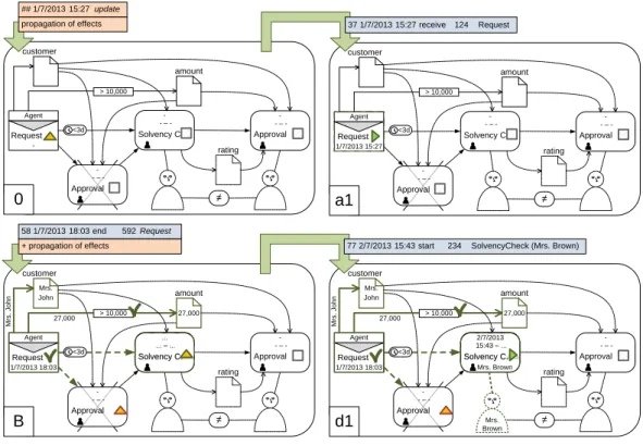
In order to enable the processing of events in the context of the extended Compliance Rule Graph (eCRG) language, this section introduces the eCRG operational semantics. In par- ticular Defs. 5-10 specify how the different event types are processed (cf. Fig. 9). First, all markings must be updated to the point-in-time of the event occured (cf. Def. 5). Second, effects of the update (i.e., the updated annotations) are propagated to adjacent elements (cf.
Def. 10). Third, Defs. 6-9 specify the actualhandling of an event based on its type. Finally, annotations are propagated once again before completing the processing of an event.
Note that the first two steps may be skipped if time does not differ from the one of the event directly processed before. In turn, these two steps may be applied without the subsequent ones in order to calculate the current state of a compliance rule at any point-in-time between two events.
5.4.1 Update Marking
Def. 5 specifies the update of a marking to the current point-in-time. In particular, the annotation of point-in-time nodes changes fromNot Marked◻to Completed✓, if the
Update Marking
Effect Propagation
Start Event Handling Message Event
Handling Effect
Propagation
End Event Handling Data Event
Handling start(…)
end(…) receive(…) send(…) read(…) write(…)
Fig. 9: Processing of start, message, data and end events
points in time to which the nodes refer have passed (t1). Furthermore, time conditions on running task nodes or sequence flow edges will beSkipped (⨉) if they are no longer satis- fiable (t2).
Definition 5 (Update Marking).
Let M ∶= (m, res, val, id, ts, te) ∈ MΨ be a marking of eCRG Ψ and let ϑ ∈ T be a point-in-time. Then:updϑ ∶MΨ →MΨ with updϑ(M) ∶= (m′, res, val, id, ts, te) calculates the updateof marking M to point-in-timeϑ, where
m′(λ) ∶=
⎧⎪⎪⎪⎪⎪⎪⎪⎪
⎪⎪⎨⎪⎪⎪
⎪⎪⎪⎪⎪
⎪⎪⎩
✓, ifλ∈P ∧m(λ) = ◻ ∧λ≤ϑ, (t1)
⨉, ifλ∈◇tc ∧m(λ) = ◻ ∧ (t∶=at(◇tc) ∈T) (t2)
∧ (∀ς∈T∶ (ς≥ϑ) ⇒ ¬◇tc(ts(t), ς)),
⨉, ifλ∈◇tc ∧m(λ) = ◻ ∧ ((n1, n2) ∶=at(◇tc) ∈# »
sf) (t2)
∧ (∀ς∈T∶ (ς≥ϑ) ⇒ ¬◇tc(te(n1), ς)), m(λ), else
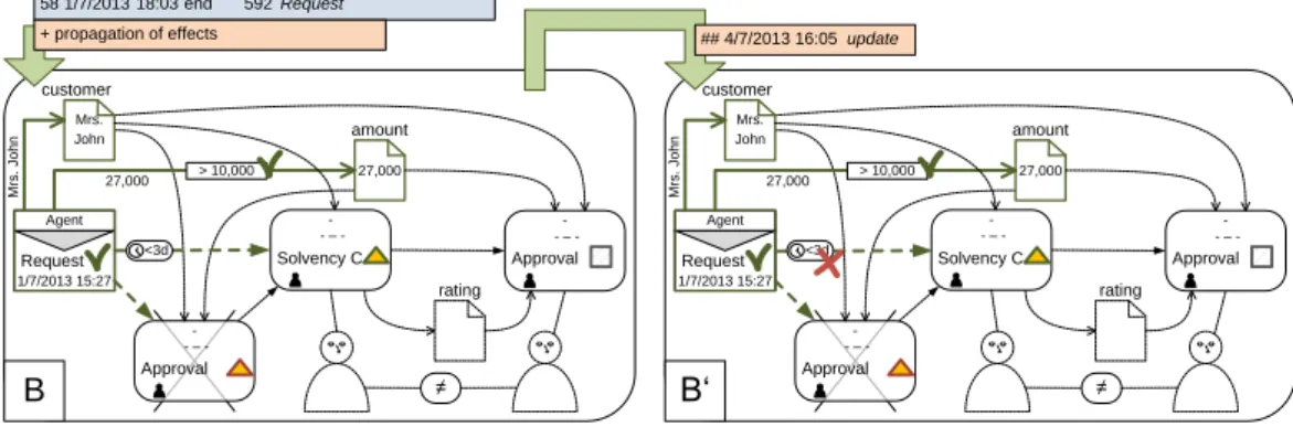
Fig. 10 updates marking B of compliance rule c1 from our motivating example (cf.
Fig. 2) to the point in time4/7/2013 16:05. According to Def. 5(t2), the time condition on the sequence flow edge from message node is marked as skipped, because it can not be satisfied any more.
Agent
rating
≠ Request
Approval - - – -
Approval - - – - Solvency C.
- - – - 1/7/2013 15:27
B
customer Mrs.
John amount
27,000
Mrs. John
27,000
58 1/7/2013 18:03 end 592 Request + propagation of effects
> 10,000
<3d
Agent
rating
≠ Request
Approval - - – -
Approval - - – - Solvency C.
- - – - 1/7/2013 15:27
B‘
customer Mrs.
John amount
27,000
Mrs. John
27,000 > 10,000
<3d
## 4/7/2013 16:05 update
Fig. 10: Update of markings
5.4.2 Start and Message Event Handling
Def. 6 (Def. 7) non-deterministically handles start events (message events), in order to deal with different instantiations of a compliance rule. In particular, the set of matching and activated task nodes (message nodes) is determined first. Then, for each subset a new mark- ing is instantiated, which solely changes the marking of the selected nodes fromActivated (△) toRunning(▶), and, accordingly, sets the identifiers, resources and starting times (cf.
Fig. 11). Node that the empty set is among the subsets and the result hence includes the unchanged original marking as well.
Definition 6 (Start Event Handling).
Let M ∶= (m, res, val, id, ts, te) ∈MΨ be a marking of eCRG Ψ and σ = start(ϑ, ι, τ, ρ) be a start event. Then:
– ∆σ(M) ∶= {λ∈T∣m(λ) = △ ∧type(λ) =τ} is the set of matchingand activated task nodes,
– For each subsetδ⊆∆σ(M),hdlδσ∶MΨ →MΨ withhdlσδ(M) ∶= (mδ, resδ, val, idδ, tδs, te) calculates the handling of start event σby node setδ and markingM:
mδ(λ) ∶= { ▶, iffλ∈δ
m(λ), else resδ(λ) ∶= {ρ, iffλ∈δ res(λ), else idδ(λ) ∶= {ι, iffλ∈δ
id(λ), else tδs(λ) ∶= {ϑ, iffλ∈δ id(λ), else
– hdlσ ∶ MΨ → 2MΨ with hdlσ(M) ∶= {hdlσδ(M)∣δ ∈ ∆σ(M)} calculates all handlings of σbyM.
Definition 7 (Message Event Handling).
Let M ∶= (m, res, val, id, ts, te) ∈MΨ be a marking of eCRG Ψ and let σ = send(ϑ, ι, τ) (andreceive(ϑ, ι, τ)respectively) be a message event. Then:
– ∆σ(M) ∶= {λ∈ MN∣m(λ) = △ ∧ type(λ) =τ} is the set of matching and activated message nodes,
– For each subsetδ⊆∆σ(M),hdlδσ∶MΨ →MΨ withhdlσδ(M) ∶= (mδ, resδ, val, idδ, tδs, te) calculates the handling of message event σby node setδ and markingM:
mδ(λ) ∶= { ▶, iffλ∈δ
m(λ), else idδ(λ) ∶= {ι, iffλ∈δ
id(λ), else tδs(λ) ∶= {ϑ, iffλ∈δ id(λ), else – hdlσ ∶ MΨ → 2MΨ with hdlσ(M) ∶= {hdlσδ(M)∣δ ∈ ∆σ(M)} calculates all handlings
of σbyM.
Fig. 11 illustrates the handling of a start and message events. In particular, the receipt of the message request starts the corresponding message node of marking 0 in the upper example; i.e., the node is marked asRunning (▶) and labeled with the receive time of the message. The lower example handles the start-event of tasksolvency check. The correspond- ing task node is marked asRunning. Furthermore, its the start time and performer of the task are specified.
Agent
rating
≠ Request
Approval - - – -
Approval - - – - Solvency C.
- - – - -
0
customer
amount
> 10,000
Agent
rating
≠ Request
Approval - - – -
Approval - - – - Solvency C.
- - – - 1/7/2013 15:27
a1
customer
amount
> 10,000
Agent
rating
≠ Request
Approval - - – -
Approval - - – - Solvency C.
- - – - 1/7/2013 18:03
B
customer Mrs.
John amount
27,000
Mrs. John
27,000 > 10,000
Solvency C.
...
... – ...
37 1/7/2013 15:27 receive 124 Request
<3d <3d
<3d
## 1/7/2013 15:27 update propagation of effects
Agent
rating
≠ Request
Approval - - – -
Approval - - – - Solvency C.
- - – - 1/7/2013 18:03
d1
customer Mrs.
John amount
27,000
Mrs. John
27,000 > 10,000
Solvency C.
2/7/2013
Mrs. Brown 15:43 – ...
<3d
Mrs.
Brown
77 2/7/2013 15:43 start 234 SolvencyCheck (Mrs. Brown) 58 1/7/2013 18:03 end 592 Request
+ propagation of effects
Fig. 11: Handling of start and message events
5.4.3 End Event Handling
Since we use unique identifiers for start, message and end events, the latter can be pro- cessed deterministically (cf. Def. 8). In particular, the annotations of all nodes assigned to the identifier of the end event and marked withRunning(▶), are changed toCompleted (✓) and their ending time is set accordingly (cf. Fig. 12).
Definition 8 (End Event Handling).
Let M ∶= (m, res, val, id, ts, te) ∈ MΨ be a marking of eCRG Ψ and σ =end(ϑ, ι, τ, ρ) (and end(ϑ, ι, τ) respectively) be an end event. Then: hdlσ ∶ MΨ → 2MΨ with hdlσ(M) ∶= {(m′, res, val, id, ts, t′e)}calculates the thehandling of end eventσby mark- ingM:
m′∶= { ✓, iffid(λ) =ι
m(λ), else t′e(λ) ∶= {ϑ, iffid(λ) =ι id(λ), else
Fig. 12 shows the handling of an end event. In particular, the processing of the message request is finished and the the corresponding message node of marking a5 is marked as Completed(✓).
Agent
rating
≠ Request
Approval - - – -
Approval - - – - Solvency C.
- - – - 1/7/2013 15:27
a6
customer Mr.
Smith amount
15,000
Mr. Smith
15,000
Agent
rating
≠ Request
Approval - - – -
Approval - - – - Solvency C.
- - – - 1/7/2013 15:27
a5
customer Mr.
Smith amount
15,000
Mr. Smith
15,000 > 10,000
propagation of effects 57 1/7/2013 18:03 write 592 amount = 27.000€
<3d
> 10,000
<3d
39 1/7/2013 15:27 end 124 Request + propagation of effects
Fig. 12: Handling of end events
5.4.4 Data Event Handling
We can also process data events deterministically, since the combination of the used unique identifiers and the used parameter names clearly refers to the data flow edges con- cerned (cf. Def. 9). In particular, the latter is marked asSatisfied(✓) and annotated with the data value and the identifier of the data source or data target; i.e., the identifier of a data container (cf. Fig. 13).
Definition 9 (Data Event Handling).
Let M ∶= (m, res, val, id, ts, te) ∈ MΨ be a marking of eCRG Ψ. Further, let σ =write(ϑ, ι, υ ÐÐ→par ω) (and read(ϑ, ι, υ ←ÐÐpar ω) respec-
tively) be a data event. Then: hdlσ ∶ MΨ → 2MΨ, with
hdlσ(M) ∶= {(m′, res, val′, id′, ts, te)} calculates the handling of data event σ by markingM:
m′(λ) ∶= { ✓, if λ= (n, t) ∈#»
df ∧m(λ) = ◻ ∧id(n) =ι∧ m(n) = ▶ ∧type(λ) =par m(λ), else
val′(λ) ∶= {υ, ifλ= (n, t) ∈#»
df ∧m(λ) = ◻ ∧id(n) =ι ∧m(n) = ▶ ∧type(λ) =par val(λ), else
id′(λ) ∶= {ω, ifλ= (n, t) ∈#»
df ∧m(λ) = ◻ ∧id(n) =ι ∧m(n) = ▶ ∧type(λ) =par id(λ), else
Fig. 13 illustrates the handling of a data events. The writing data flow event amount of the messagerequest is handled in the upper example. In particular, the corresponding outgoing data flow edge of message noderequest is marked asSatisfied(✓) and annotated with the amount of15.000. The lower example handles the reading data flow eventcustomer that marks the incoming data flow edge of tasksolvency check asSatisfied(✓) and anno- tates it with the customerMr. Smith. Note that the latter annotationMr. Smith does not meet the valueMrs. Johnof the data objectcustomer; i.e., the handling of data flow events allows for conflicts. Furthermore, note that we omit the identifiers of data sources (i.e., data containers) in our examples for the sake of simplicity.
Agent
rating
≠ Request
Approval - - – -
Approval - - – - Solvency C.
- - – - 1/7/2013 15:27
a3
customer
amount propagation of effects
15,000 > 10,000
Agent
rating
≠ Request
Approval - - – -
Approval - - – - Solvency C.
2/7/2013
Mrs. Brown 15:43 – ...
1/7/2013 18:03
d3
customer Mrs.
John amount
27,000
Mrs. John
27,000 > 10,000
Mr. Smith
<3d
<3d
Mrs.
Brown 38 1/7/2013 15:27 write 124 amount = 15.000€
Agent
rating
≠ Request
Approval - - – -
Approval - - – - Solvency C.
- - – - 1/7/2013 15:27
a2
customer
amount
> 10,000
<3d
37 1/7/2013 15:27 receive 124 Request
Agent
rating
≠ Request
Approval - - – -
Approval - - – - Solvency C.
- - – - 1/7/2013 18:03
d2
customer Mrs.
John amount
27,000
Mrs. John
27,000 > 10,000
Solvency C.
2/7/2013
Mrs. Brown 15:43 – ...
<3d
Mrs.
Brown
propagation of effects 78 2/7/2013 15:43 read 234 customer = Mr.Smith
77 2/7/2013 15:43 start 234 SolvencyCheck (Mrs. Brown)
Fig. 13: Handling of data events
5.4.5 Propagation of effects
After each update or event handling, we propagate the corresponding effects (i.e., changes to annotations) on adjacent nodes and edges in order to ensure correct annotations (e.g., activation of subsequent task nodes). Further, we detect contradictory annotations related to the data and resource perspectives (cf. Def. 10).
In particular, resources are propagated from task nodes toNot Marked(◻), dependent resource nodes (r2) by following resource edges (r1). In turn, data values and the identifiers of data containers are propagated from data flow edges to Not Marked(◻), dependent data object nodes (d1) as well as data container nodes (d2). Next, the edge and its target node are marked withSatisfied(✓) (x3).
Note that the aforementioned propagation steps are not performed, if resources, data values or identifiers of target resource nodes, data objects or data containers were already set to another value before. To highlight such conflicts, the corresponding data flow and resource edges will be marked withSkipped (⨉) (x4). Not Marked(◻) data flow edges will be also marked withSkipped(⨉) if the corresponding task or message node is completed (d5). Afterwards, all conditions (x6) and relations are reevaluated (x7). If any element of the eCRG, affiliated to a dependent task or message node, is now Skipped (⨉), the corresponding task or message node will be marked withSkipped (⨉) as well (x8).
Next, the outgoing sequence flows of completed nodes are marked with Satisfied(✓) (cf1). In turn,Not Marked(◻), incoming sequence flow edges of already started nodes are marked with Skipped (⨉). Further, sequence flow edges from and to Skipped (⨉) nodes
![Fig. 1: Compliance monitoring [10, 5]](https://thumb-eu.123doks.com/thumbv2/1library_info/5213248.1669056/2.892.203.683.543.832/fig-compliance-monitoring.webp)
![Fig. 3: CRG example and semantics [8]](https://thumb-eu.123doks.com/thumbv2/1library_info/5213248.1669056/6.892.192.701.619.793/fig-crg-example-and-semantics.webp)
![Fig. 4: Elements of the eCRG language [17, 18]](https://thumb-eu.123doks.com/thumbv2/1library_info/5213248.1669056/7.892.195.705.250.560/fig-elements-ecrg-language.webp)