Visual Modeling of Business Process Compliance Rules with the Support of Multiple Perspectives
⋆David Knuplesch1, Manfred Reichert1, Linh Thao Ly1, Akhil Kumar2, and Stefanie Rinderle-Ma3
1 Institute of Databases and Information Systems, Ulm University, Germany david.knuplesch,manfred.reichert,thao.ly@uni-ulm.de
2 Smeal College of Business, Pennsylvania State University, PA, USA akhilkumar@psu.edu
3 Faculty of Computer Science, University of Vienna, Austria stefanie.rinderle-ma@univie.ac.at
Abstract. A fundamental challenge for any process-aware information system is to ensure compliance of modeled and executed business pro- cesses with imposed compliance rules stemming from guidelines, stan- dards and laws. Such compliance rules usually refer to multiple process perspectives including control flow, time, resources, data, and interac- tions with business partners. On one hand, compliance rules should be comprehensible for domain experts who must define and apply them. On the other, they should have a precise semantics such that they can be au- tomatically processed. In this context, providing a visual compliance rule language seems promising as it allows hiding formal details and offers an intuitive way of modeling. So far, visual compliance rule languages have focused on the control flow perspective, but lack adequate support for the other perspectives. To remedy this drawback, this paper provides an approach that extends visual compliance rule languages with the ability to consider data, time, resources, and partner interactions when model- ing business process compliance rules. Overall, this extension will foster business process compliance support in practice.
Keywords: business process compliance, compliance rule graphs, busi- ness process modeling, business intelligence
1 Introduction
During the last decade, numerous approaches for ensuring the correctness of busi- ness processes have been discussed [1, 2]. Most of them focus on syntactical cor- rectness and process model soundness (e.g., absence of deadlocks and lifelocks).
However, business processes must also comply with semantic rules stemming from domain-specific requirements such as corporate standards or legal regula- tions [3]. Summarized under the notion ofbusiness process compliance, existing
⋆This work was done within the research project C3Pro funded by the German Re- search Foundation (DFG), Project number: RE 1402/2-1, and the Austrian Science Fund (FWF) under project number: I743.
approaches have mostly considered compliance issues related to the control flow perspective of single processes. By contrast, cross-organizational scenarios char- acterized by interacting and collaborating business processes of various parties have not been properly considered so far [4]. Furthermore, compliance require- ments for both local and global process scenarios do not only concern control flow and interactions between business partners (i.e. messages exchanged), but also refer to time, resources, and data [5–8]. As examples, consider the compliance rules in Tab. 1, which are imposed on a cross-organizational process scenario involving the two business partnersreseller andmanufacturer. In particular, as shown by the highlighted terms in Tab. 1, the rules that arise in practice should be able to describe aspects of interaction, time, resource and data as they relate to a business process. Hence, these various perspectives of a business process should be modeled to support compliance.
Compliance rule c1 considers a pair of interactions between a reseller and manufacturer (request andreply) after a particular point in time (3rd January, 2013) as well as the maximum time delay between them (within three days).
The data perspective of compliance rules is emphasized by compliance rulec2of the manufacturer. It forbids changing an order after having started the corre- spondingproduction task. Compliance rulec3in turn, combines the interaction, time, and data perspectives. Finally, compliance rulec4 introduces the resource perspective (member of the order processing departmentandanother member of the same department with supervisor status). In addition,c4 considers the data perspective (e.g.new customer andtotal amount greater than e5,000) and the time perspective (at most three days). Particularly c4 shows that the different perspectives might be relevant for the same rule and hence cannot be considered in an isolated manner.
Comparing c4 andc2 withc1 andc3, one can further notice two different view- points:c4andc2are expressed from the viewpoint of the manufacturer (i.e., local view), whilec1 andc3reflect a global view. Note that such distinction between local and global views is common to cross-organizational collaboration scenarios not only in the context of process compliance. For example, BPMN 2.0 provides collaboration and choreography diagrams to express these different viewpoints.
Table 1: Examples of compliance rules for order-to-delivery processes c1 Anyrequest sent from the reseller to the manufacturerafter January 3rd, 2013
should bereplied by the manufacturerwithin three days.
c2 After starting the production related to a particularorder, the latter must not be changed anymore.
c3 When the manufacturersends a bill with anamount lower thane5,000 to the reseller, the latter must make the paymentwithin 7 days.
c4 After receiving a production request message from the reseller, which refers to a new customer and has a total amount greater than e5,000, the solvency of this customer must be checked by amember of the order processing department.
Based on the result of this check,another member of the same department with supervisor statusmust approve the request. Finally, the approval result must be sent to the resellerat most three days after receiving the original request.
Several approaches for formally capturing compliance requirements at differ- ent abstraction levels (e.g., temporal logics [9]) exist to enable the automatic verification of compliance of business processes with such rules. As the use of formal languages for compliance rule specifying might become too intricate, rule patterns [6, 8], which hide formal detail from rule modelers, have been proposed.
Furthermore, a few approaches also consider more advanced issues like, e.g., the use of data conditions in the context of compliance requirements. However, existing approaches are usually restricted to a specific subset of rule patterns.
In this context, rule languages, employing visual notations like the compliance rule graph approach [10] or BPSL [11], provide an alternative as they combine an intuitive notation with the advantages of a formal language. However, our meta-analyses and case studies, we conducted in domains like higher education, medicine and automotive engineering, have revealed that these visual compliance rule languages still lack support for the time, data, and resource perspective of business processes. Our analyses have further shown that existing compliance rule notations do not consider cross-organizational scenarios with interacting partners [4]. Overall, in our meta-analyses and case studies, we elicited the fol- lowing fundamental requirements for visual compliance rule languages:
– In addition to the control flow perspective, the data, resource and time per- spectives of compliance requirements must be properly captured.
– To not only consider process orchestrations, but cross-organizational scenar- ios as well, it becomes necessary to express the interaction perspective with compliance rule languages.
– To provide tool support for both the modeling and verification of compliance rules, their syntax as well as semantics must be formalized.
To cope with the shortcomings discussed above, we introduce extensions for visual compliance rule modeling supporting the data, time, and resource per- spectives of business processes. More precisely these extensions are proposed for the compliance rule graph (CRG) language we developed in earlier work [10, 12]. However, the major concepts we propose may be applied to other com- pliance rule languages as well. Another fundamental contribution is the ability of our extended compliance rule graph language to specify compliance require- ments for cross-organizational scenarios (i.e. processes choreographies) as well.
For this purpose, we additionally introduce concepts that allow defining compli- ance rules in respect to message flows and partner interactions. Altogether, the visual compliance rule language developed in this paper allows capturing com- pliance requirements at an abstract level, while at the same time it enables the specification of verifiable compliance rules in the context of cross-organizational scenarios.
The remainder of this paper is structured as follows: Sect. 2 discusses re- lated work. In Sect. 3, we introduce the data, time, resource, and interaction perspective of compliance rules. Our extensions of the CRG language regarding the support of these perspectives, theextended compliance rule graphs (eCRG), are described in Sect. 4. To validate our approach, we present a proof-of-concept prototype and outline the results of a pattern-based evaluation in Sect. 5. Sect. 6 concludes the paper and provides an outlook on future research.
2 Related Work
Recently modeling issues related to the interaction, time, resource, and data perspectives of business processes have been addressed in addition to the control flow perspective (e.g., [13–19]).
The integration of business process compliance throughout the entire process lifecycle has been discussed in [12, 20–22]; [23] examined compliance issues in the context of cross-organizational processes developing a logic-based formalism for describing both the semantics of normative specifications and compliance check- ing procedures. This approach allows modeling business obligations and regu- lating the execution of business processes. In turn, [24] introduced a semantic layer that interprets process instances according to an independently designed set of internal controls. Furthermore, there exist approaches using semantic an- notations to ensure compliance [25]. An approach checking the compliance of process models against semantic constraints as well as ensuring the validity of process change operations based on Mixed-Integer Programming formulation is proposed in [26]. It introduces the notions of degree of compliance, validity of change operations, andcompliance by compensation. [6] uses alignments to de- tect compliance violations in process logs. To verify whether compliance rules are fulfilled by process models at design time, many approaches apply model checking techniques [9, 11, 27–29]; some of them address the data and time per- spectives as well. Further approaches for verifying compliance apply the notion ofsemantic congruence[30] or usepetri-nets[31] and consider the data and time perspectives as well.
The approach described in [27, 32] for visually modeling compliance consid- ers the control flow and data perspectives. It is based on linear temporal logic (LTL), which allows modeling the control flow perspective based on operators likenext,eventually,always, anduntil. Finally, visual approaches for compliance rule modeling exist [11, 10, 33]. However, they focus on control flow and partly the data perspective, but ignore the other perspectives mentioned.
3 Compliance Perspectives
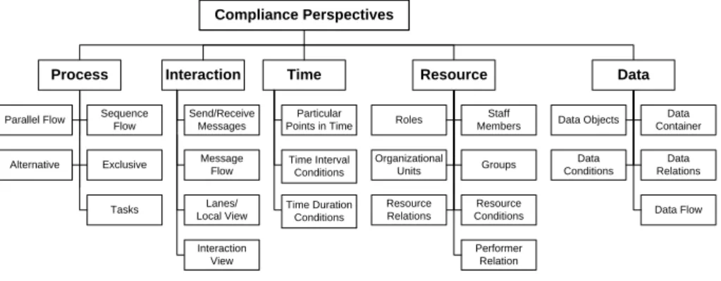
As noted above, compliance rules cannot be expressed completely by referring only to the control flow perspective of a business process. In [5–8], the impor- tance of the time, resources, and data perspectives are emphasized. The need for ensuring compliance in the context cross-organizational scenarios is raised in [4]. Before introducing the visual notation of the eCRG language, we describe the compliance perspectives as well as related language concepts in more detail.
The latter have been elicited through our analyses and case studies. Fig. 1 pro- vides an overview of the perspectives we consider and characterizes their main features.
Process Perspective.The process (i.e. control flow) perspective of compliance rules is the most fundamental one. It comprises elements for expressing both the occurrence and presence (i.e.,exclusive,alternative) of tasksas well as their ordering (i.e.,sequence flow,parallel flow).
Compliance Perspectives
Time Interaction
Staff Members
Groups Organizational
Units
Performer Relation Roles
Resource Conditions Sequence
Flow
Tasks
Data Container Data Objects
Data Flow Data Relations Data
Conditions Parallel Flow
Exclusive
Resource Relations Alternative
Particular Points in Time
Time Interval Conditions
Time Duration Conditions Send/Receive
Messages
Message Flow
Interaction View Lanes/
Local View
Resource Data
Process
Fig. 1: Compliance perspectives
Interaction Perspective. In cross-organizational scenarios, compliance rules require particular elements for sending and receiving messages. Message flows correlate the sending and receiving of messages. Further, lanes express local views of the different partners on the different tasks to be performed. In turn, theinteraction viewfocuses on the global sequence of interactions (i.e., messages exchanged). Compared to BPMN 2.0, local views correspond to collaboration diagrams andinteraction views tochoreography diagrams.
Time Perspective.Time support for compliance rules is tripartite: First, par- ticular points in time may have to be expressed (e.g.Monday,3rd January 2013).
Second, conditions on the time intervals between events, tasks and points in time require support. Third, the duration of tasks may have to be constrained.
Resource Perspective.The resource perspective requires concepts for express- ing constraints onresources. We selectstaff member,group,organizational unit, and roles as common concepts of organizational models. However, this list can be extended easily. Theperformer relationconstrains the performer of a partic- ular task. In turn,resource conditions andrelations may be used to specify and constrain resources on a finegrained level.
Data Perspective. The data perspective comprises concepts for expressing data-aware compliance rules. Thereby,data containers refer to process data el- ements or global data stores. By contrast, data objects refer to particular data values and object instances.Data flow defines which process tasks read or write which data objects or data container. To constrain data container, data objects, and data flow, data conditions anddata relations may be used.
In the following, required language extensions are presented taking the com- pliance rule graph (CRG) language as basis (cf. Sec. 4.1). However, these exten- sions may be applied to other compliance rule languages as well, since they are independent from particular properties of CRGs.
4 Extended Compliance Rule Graphs
This section introduces extended Compliance Rule Graphs (eCRG) - a visual notation for compliance rule modeling covering the process, interaction, time,
resource, and data perspectives (cf. Section 3). Sect. 4.1 introduces fundamentals of CRGs, while its extensions are subsequently introduced step-by-step.
4.1 Fundamentals of Compliance Rule Graphs
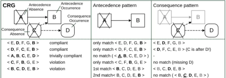
The compliance rule graph (CRG) language [10, 12] allows visually modeling compliance rules whose semantics is defined over event traces. More precisely, a CRG is an acyclic graph consisting of an antecedence pattern as well as at least one related consequence pattern. Both patterns are modeled usingoccur- rence and absence nodes, which indicate the occurrence or absence of events (e.g., related of the execution of a particular task). Edges between such nodes indicate control flow dependencies. As illustrated in Fig. 2, a trace is considered as compliant with a CRG iff for each match of the antecedence pattern there is at least one corresponding match of every consequence pattern. Further, a trace is considered astrivially compliant iff there is no match of the antecedence pat- tern. For example, the CRG from Fig. 2 expresses that for eachB not preceded by anA, there must occur aD, which is not preceded by anyC also preceding the respectiveB.
C D C D
Antecedence pattern Consequence pattern
only match < E, D, F, G, B >
only match < D, F, C, E, B >
no match ( < A, B, C, E, D > ) only match < C, F, B, G, E >
1st match < B, C, D, E, B >
2nd match< B, C, D, E, B >
< E, D, F, G, B >
< D, F, C, E, B > (C is after D!) -
no match (missing D)
< B, C, D, E, B >
no match ( < B, C, D, E, B > )
A B
A B A B
< E, D, F, G, B >
< D, F, C, E, B >
< A, B, C, E, D >
< C, F, B, G, E >
< B, C, D, E, B >
compliant compliant trivially compliant violation violation
Antecedence Occurrence Antecedence
Absence
Consequence Absence
Consequence Occurrence
CRG
Fig. 2: CRG example and semantics over execution traces
In the following, we introduce the eCRG language, which is based on CRGs.
Note that in addition to nodes and connectors (i.e., edges) as fundamental el- ements of graphs, eCRGs further support attachments. Attachments represent constraints to the nodes or edges they are attached to. Further, eCRGs may contain instance nodes representing particular instances, which exist indepen- dently from the respective rule (e.g. a particular employee Mr. Smith, date3rd January 2013, or rolesupervisor). Hence instance nodes are neither part of the antecedence nor the consequence pattern.
4.2 Process Perspective
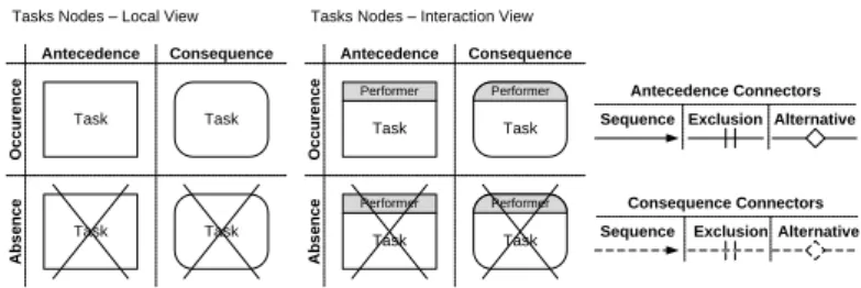
The eCRG elements for modeling the process (i.e. control flow) perspective of compliance rules are introduced in Fig. 3. Since the extensions are based on the CRG language, there are four different task elements, i.e., antecedence oc- currence,antecedence absence,consequence occurrence, andconsequence absence task. These allow expressing whether or not particular tasks must be executed.
Performer
Task Task
Performer
Task Tasks Nodes – Local View
Antecedence Consequence
OccurenceAbsence
Task Task
Task
Tasks Nodes – Interaction View Antecedence Consequence
OccurenceAbsence
Performer
Task Task
Performer
Sequence Exclusion Antecedence Connectors
Sequence Exclusion Consequence Connectors
Alternative
Alternative
Fig. 3: eCRG elements of the process perspective
In addition, two different kinds of sequence flow connectors are provided that may be used to constrain the execution sequence of tasks. Note that the absence of sequence flow indicates parallel flow. To clearly distinguish between start- start,start-end,end-start, andend-end constraints on the execution sequence of tasks, sequence flow edges are either connected to the right or left border of a task node. Furthermore, exclusive connectors denote mutual exclusion of tasks.
Alternative connectors express that at least one of the connected tasks must occur. Note that exclusive as well as alternative connectors may only connect nodes that are both part of either the antecedence or consequence pattern.
Fig. 5A shows an example of a start-start constraint on the execution se- quence of tasks. It depicts the process perspective of compliance rule c2 from Tab. 1. Note that this visual compliance rule disallows executing task change order after the start of taskproduction.
4.3 Interaction Perspective
The interaction perspective covers constraints on the messages exchanged and theinteraction view of the eCRG meta-model. Message exchanges are expressed in terms of particular nodes that reflect the events of sending and receiving a message. In turn, a message flow denotes the dependency between the events representing the sending and receiving of a particular message (cf. Fig. 4).
Antecedence Consequence Antecedence Consequence
Sender
Message Receiver
Sender
Message Receiver
Sender
Message Receiver
Sender
Message Receiver
Antecedence Consequence
OccurenceAbsence
Antecedence Message Flow Connector Consequence Message Flow Connector Interaction Nodes – Interaction View
Message Nodes – Local View
Sender
Receiver Message
Message
Sender
Message Receiver
Message
Sender
Receiver Message
Message
Sender
Message Receiver
Message
Receive Send
OccurenceAbsence
Fig. 4: eCRG elements of the interaction perspective
In Fig. 5B, the elements from Fig. 4 are used to model the process and inter- action perspective of compliance rule c4. This rule requires that after receiving messagerequest from a reseller, asolvency check must be performed first. Then,
a decision aboutapproval has to be made before replying the request. Although the rule modeled in Fig. 5B considers the interaction perspective, using the two message nodesrequest andreply, it still represents the view of a particular busi- ness partner on its local business processes. We refer to this traditional point of view as the local view of a compliance rule. However, when considering the choreography diagram of BPMN 2.0 or compliance rules c1 andc3 from Tab. 1, one can easily discover a global point of view on cross-organizational processes and related interactions (i.e., the messages exchanged). In thisinteraction view, interaction nodes (cf. Fig. 4) are used to denote the exchange of a message be- tween two business partners. Since the interaction view spans multiple business partners, task nodes may be annotated with the executing business partner if required (cf. Fig. 3).
Production
Change Order
Reseller
Reseller Reply Check
Solvency Approval
Request
A B
Fig. 5: Local view onc2andc4 with process and interaction perspectives
Reseller
Request Manufacturer
Manufacturer
Reply Reseller
Manufacturer
Billing Information
Reseller
Payment Reseller B
A
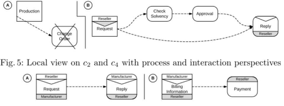
Fig. 6: Interaction view onc1andc3 with process and interaction perspectives Fig. 6A provides an interaction view on compliance rulec1from Tab. 1: After the reseller sends a request to the manufacturer, eventually, the manufacturer mustreply. Further, Fig. 6B provides an interaction view on compliance rulec3
from Tab. 1. This rule requires that the reseller must perform taskpayment after having receivedbilling information from the manufacturer.
4.4 Time Perspective
Having a closer look on the original definition of compliance rules c1 and c3 from Tab. 1, it becomes clear that Figs. 6A and 6B do not fully cover them yet.
In particular, the distance in time between the interactions and tasks have not been considered. Fig. 7 provides elements for modelingpoints in time andtime conditions in compliance rules. The latter may be attached to task nodes as well as sequence or message flow connectors to either constrain the duration of a task or the time distance between tasks, messages, and points in time. Additionally, time distance connectors are introduced that must be attached with a time condition. Respective time distance connectors and related time conditions then allow constraining the time distance between tasks, messages, and points in time without implying a particular sequence.
Fig. 8A combines the interaction and time perspectives of compliance rulec1. This visual representation ofc1 covers exactly the semantics of the compliance
Occurence Anteced.
Points in Time
Antecedence Consequence Time Conditions
>2d
>2d
Anteced. Sequence Distance Connector Consequ. Sequence Distance Connector Absence
March 23th 2013 Particular Point in Time Consequ.
Fig. 7: eCRG elements of the time perspective
Reseller
Request Manufacturer
Manufacturer
Reply Reseller
< 3 days Jan 3rd
2013
Manufacturer
Billing Information
Reseller
Payment Reseller
< 7days
A B
Fig. 8: Interaction view onc1andc3with process, interaction, and time perspec- tives
rule described in Tab. 1. In Fig. 8B, the interaction and time perspectives ofc3
are provided. This compliance rule requires that at most seven days after the manufacturer sendsbilling information to the reseller, the latter must perform taskpayment.
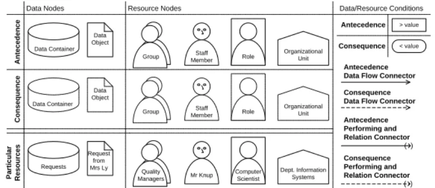
4.5 Resource Perspective
The resource perspective covers the different kinds of human resources as well as their inter-relations, and it allows constraining the assignment of resources to tasks. In particular, we consider resources likestaff member,role,group, and organizational unit, and their relation to tasks. Furthermore, we support re- source conditions and relations among resources (cf. Fig. 9). Similar to task nodes, resource nodes may be part of the antecedence or consequence pattern.
Alternatively, they may represent a particular resource instance (e.g. staff mem- ber Mr. Smith, or role supervisor). In turn, resource conditions may constrain resource nodes. Further, the performing relation indicates the performer of a task. Finally, resource relation connectors express relations between resources.
Note that the resource perspective can be easily extended with other kinds of resources if required.
< value
> value Antecedence
Consequence Data/Resource Conditions
Data Object Data Object Data Nodes
AntecedenceConsequence
Antecedence Data Flow Connector Consequence Data Flow Connector
Group Organizational
Staff Unit
Member Role
Group Organizational
Staff Unit
Member Role
Resource Nodes
Antecedence Performing and Relation Connector
Consequence Performing and Relation Connector
( )
( ) Data Container
Data Container
Requests Request
from Mrs Ly Particular Resources
Quality Managers
Dept. Information Systems
Mr Knup Computer
Scientist
Fig. 9: eCRG elements of the resource and data perspectives
Supervisor
Reseller
Request
Reseller Reply Check
Solvency Approval
< 3 days
≠
Order Processing Department
assigned is
assigned
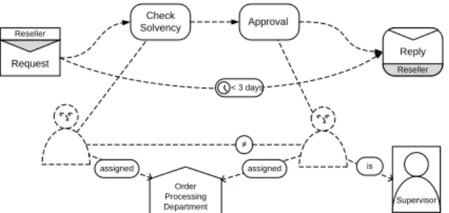
Fig. 10: Local view onc4 with process, interaction, time, and resource perspec- tives
Fig. 10 combines the process, interaction, time, and resource perspectives of compliance rulec4. This rule requires that at least three days after receiving a request of the reseller, a replay must be sent to him. Before sending this reply, first of all, tasksolvency check must be performed by a staff member assigned to the particular organizational unitorder processing department. Following this task, another staff member of the same department withsupervisor status (i.e., role) must decide whether or not to grant approval before sending thereply.
4.6 Data Perspective
Fig. 9 introduces elements for modeling data containers and data objects as well as connectors representing data flow. Thereby, data containers refer to process data elements or global data stores. By contrast,data objects refer to particular data values and object instances. Similar to resource nodes,data nodes may be part of the antecedence or consequence pattern, or represent a particular data container or data object (e.g., data containerstudent credit points, document1st order from Mr. Smith). Further, data flow defines which process tasks read or write which data objects or data container. To constrain data container, data objects, and data flow, data conditions may be attached. Finally, data relation connectors may be used either to compare different data objects or to constrain the value of data containers at particular points in time.
Figs. 11A, 11B, and 11C show the visual modeling of compliance rulesc2,c3, andc4 covering the data perspective as well as the other perspectives discussed.
Each of the depicted eCRGs covers the informal semantics described in Tab. 1.
5 Discussion and Validation
Sect. 4 introduced the eCRG language, which comprises various elements for modeling the process, interaction, time, resource, and data perspectives of com- pliance rules. However, note that the introduced elements must not be arbitrar- ily combined, but should follow syntactic constraints. First, any eCRG must be acyclic. Second, antecedence and consequence connectors must be applied in a reasonable way, e.g., any sequence flow between an antecedence absence and a
Customer data
Supervisor
Reseller
Request Reseller
Reply amount > 5000 €
Check
Solvency Approval
< 3 days
Request Approval
Result
new customer?
≠
Order Processing Department
assigned Solvency
result
assigned is
Production
Change Order Order
Manufacturer
Billing Information
Reseller
Payment Reseller
< 7days Bill
amount < 5000 € A
B
C
Fig. 11: Local view onc2and interaction view onc3andc4, considering process, interaction, time, resource, and data perspectives
consequence absence node does not make sense, and hence is forbidden. Third, the use of attachments is restricted in a similar way. Finally, exclusive and al- ternative connectors must only connect tasks, messages, or interaction nodes of the same pattern. Fig. 13 summarizes valid and invalid use cases of connectors and attachments.
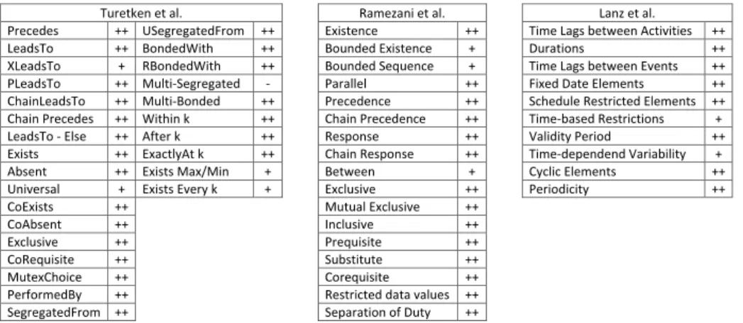
To the best of our knowledge, our approach is the first one that allows mod- eling compliance rules visually considering the interaction, time, resource, and data perspectives. Note that there exist pattern-based approaches that model compliance rules supporting at least the time, resource, and data perspectives [6, 8, 34]. These patterns resulted from literature and case studies, and thus con- stitute a suitable empirical basis for evaluating the appropriateness of our ap- proach. Therefore, we modeled the compliance patterns introduced in [6, 8, 34]
with our visual notation in [35]. Overall, we were able to fully model 26 out of the 27 business process control patterns from [8], including 5 time patterns and 7 resource patterns as well. Only the multi-segregation pattern cannot be mod- eled as eCRG [35]. Further, eCRGs allow modeling each of the 15 control flow compliance rules as well as the data flow restrictions and organizational aspects (i.e., separation of duty) from [6]. Finally, the time-patterns introduced in [16]
can also be covered with eCRGs [35]. Note that the proposed visual notation (i.e., eCRG) is not restricted to these patterns (e.g., c4 cannot be modeled by the use of compliance patterns).
Any syntactically correct eCRG can be converted into a corresponding FOL formula. The FOL formula, in turn, can be evaluated over process traces, includ- ing the process, interaction, time, resource, and data perspectives. Furthermore, the internal consistency (i.e., absence of conflicts) of a set of compliance rules can be verified. We provide details on the transformation of eCRG into FOL formula (i.e., the formal semantics of eCRGs) and the subsequent verification over process traces in [35]. We have demonstrated the feasibility of our modeling approach by implementing a proof-of-concept prototype of a modeling environ- ment for eCRGs, which we then used to model compliance rules from a variety
Turetken et al. Ramezani et al. Lanz et al.
Precedes ++ USegregatedFrom ++ Existence ++ Time Lags between Activities ++
LeadsTo ++ BondedWith ++ Bounded Existence + Durations ++
XLeadsTo + RBondedWith ++ Bounded Sequence + Time Lags between Events ++
PLeadsTo ++ Multi-Segregated - Parallel ++ Fixed Date Elements ++
ChainLeadsTo ++ Multi-Bonded ++ Precedence ++ Schedule Restricted Elements ++
Chain Precedes ++ Within k ++ Chain Precedence ++ Time-based Restrictions +
LeadsTo - Else ++ After k ++ Response ++ Validity Period ++
Exists ++ ExactlyAt k ++ Chain Response ++ Time-dependend Variability +
Absent ++ Exists Max/Min + Between + Cyclic Elements ++
Universal + Exists Every k + Exclusive ++ Periodicity ++
CoExists ++ Mutual Exclusive ++
CoAbsent ++ Inclusive ++
Exclusive ++ Prequisite ++
CoRequisite ++ Substitute ++
MutexChoice ++ Corequisite ++
PerformedBy ++ Restricted data values ++
SegregatedFrom ++ Separation of Duty ++
++ full support, + inconvenient support, 0 partial support, - minor support, -- no support
Fig. 12: Support of compliance patterns with eCRGs
AO AA
AO AA
CO CA
CO CA
X
X X
X X X
ok ok
ok ok
ok ok
ok X
X ok
AO AA
AO AA
X ok ok
ok
AO AA CO CA
ok ok X X AO
AA AO AA
CO CA
CO CA
ok
X X
ok X X
ok X
X X
ok ok
ok ok
ok X
antecedence connector sequence flow
consequence connector sequence flow
antecedence attachments
exclusive / alternative connectors
AO AA CO CA X
ok ok ok
consequence attachments antecedence occurrence node
antecedence absence node consequence occurrence node consequence absence node AO
AA CO CA
Fig. 13: Valid Use of eCRG elements
Fig. 14: Proof-of-concept implementation
of domains including higher education, medicine and automotive engineering. In particular, domain experts have been able to define and understand the visual notation we used. We are currently preparing user experiments to check how end users deal with large sets of visual compliance rules. Fig. 14 provides a screenshot of our prototype.
6 Summary and Outlook
While compliance rule modeling has been introduced by a plethora of approaches, the data, time, and resource perspectives of compliance rules have not been suf- ficiently addressed yet [5–8]. This paper introduces extensions for visual com- pliance rule languages to support these perspectives. In particular theses exten- sions are introduced as part ofextended compliance rule graphs (eCRG), which are based on the compliance rule graph (CRG) language [10, 12]. However, the modeling elements described may be applied to other compliance rule languages as well. Besides the data, time, and resource perspectives, we further suggest elements for modeling the interaction perspective of compliance rules. To pro- vide tool support for both the modeling and verification of compliance rules, we formalize the syntax and semantics of eCRGs in a technical report [35].
Finally, pattern-based analysis has shown that eCRGs have sufficient expessive- ness. Our next step will be an experiment to evaluate the usability and scalability of eCRGs. Further, we will apply the proposed extensions to other compliance rule languages. Finally, we will develop techniques for verifying compliance of business processes and process choreographies with such rules.
References
1. Reichert, M., Weber, B.: Enabling Flexibility in Process-Aware Information Sys- tems. Springer (2012)
2. van der Aalst, W.M.P.: Verification of workflow nets. Application and Theory of Petri Nets (1997) 407–426
3. Sadiq, S., Governatori, G., Naimiri, K.: Modeling control objectives for business process compliance. In: BPM’07. (2007)
4. Knuplesch, D., et al.: Towards compliance of cross-organizational processes and their changes. In: Proc SBP’12, Springer (2012)
5. Cabanillas, C., Resinas, M., Ruiz-Cort´es, A.: Hints on how to face business process compliance. In: JISBD’10. (2010)
6. Ramezani, E., Fahland, D., van der Aalst, W.M.: Diagnostic information in com- pliance checking. In: BPM’12, Springer (2012)
7. Mangler, J., Rinderle-Ma, S.: Iupc: Identification and unification of process con- straints. arXiv. org (2011)
8. Turetken, O., Elgammal, A., van den Heuvel, W.J., Papazoglou, M.: Capturing compliance requirements: A pattern-based approach. IEEE Soft (2012) 29–36 9. Ghose, A.K., Koliadis, G.: Auditing business process compliance. In: ICSOC’07.
(2007) 169–180
10. Ly, L.T., et al.: Design and verification of instantiable compliance rule graphs in process-aware information systems. In: CAiSE’10. (2010) 9–23
11. Liu, Y., M¨uller, S., Xu, K.: A static compliance-checking framework for business process models. IBM Systems Journal46(2) (2007) 335–261
12. Knuplesch, D., Reichert, M.: Ensuring business process compliance along the pro- cess life cycle. Technical Report 2011-06, Ulm University (2011)
13. Russell, N., et al.: Workflow resource patterns: Identification, representation and tool support. In: CAiSE’05, Springer (2005) 216–232
14. Kumar, A., Wang, J.: A framework for document-driven workflow systems. In:
Int’l Handbook on Business Process Management. Springer (2010) 419–440 15. Eder, J., Tahamtan, A.: Temporal conformance of federated choreographies. In:
DEXA’08. (2008) 668–675
16. Lanz, A., Weber, B., Reichert, M.: Time patterns for process-aware information systems. Requirements Engineering (2012)
17. Decker, G., Weske, M.: Interaction-centric modeling of process choreographies. Inf Sys35(8) (2010)
18. Barros, A., Dumas, M., ter Hofstede, A.: Service interaction patterns. In: BPM’05.
(2005) 302–318
19. Knuplesch, D., et al.: Data-aware interaction in distributed and collaborative workflows: Modeling, semantics, correctness. In: CollaborateCom’12. (2012) 223–
232
20. Ly, L.T., et al.: Integration and verification of semantic constraints in adaptive process management systems. Data & Knowl Eng64(1) (2008) 3–23
21. Ly, L.T., et al.: On enabling integrated process compliance with semantic con- straints in process management systems. Inf Sys Front14(2) (2012) 195–219 22. Ramezani, E., et al.: Separating compliance management and business process
management. In: BPM Workshops, Springer (2012) 459–464
23. Governatori, G., Sadiq, S.: The journey to business process compliance. In: Hand- book of Research on BPM. IGI Global (2009) 426–454
24. Namiri, K., Stojanovic, N.: Pattern-Based design and validation of business process compliance. In: CoopIS’07. (2007) 59–76
25. Governatori, G., et al.: Detecting regulatory compliance for business process mod- els through semantic annotations. In: BPM Workshops, Springer (2009) 5–17 26. Kumar, A., Yao, W., Chu, C.: Flexible process compliance with semantic con-
straints using mixed-integer programming. INFORMS J on Comp (2012)
27. Awad, A., Weidlich, M., Weske, M.: Specification, verification and explanation of violation for data aware compliance rules. In: ICSOC’09. (2009) 500–515
28. Knuplesch, D., Ly, L.T., Rinderle-Ma, S., Pfeifer, H., Dadam, P.: On enabling data-aware compliance checking of business process models. In: ER’2010. (2010) 29. Kokash, N., Krause, C., de Vink, E.: Time and data aware analysis of graphical
service models. In: SEFM’10. (2010)
30. H¨ohn, S.: Model-based reasoning on the achievement of business goals. In: SAC
’09, New York, NY, USA, ACM (2009) 1589–1593
31. Accorsi, R., Lowis, L., Sato, Y.: Automated certification for compliant cloud-based business processes. Business & Inf Sys Engineering3(3) (2011) 145–154
32. Awad, A., Weidlich, M., Weske, M.: Visually specifying compliance rules and exp- laining their violations for business processes. Vis Lang Comp22(1) (2011) 30–55 33. Feja, S., Speck, A., Witt, S., Schulz, M.: Checkable graphical business process
representation. In: ADBIS’11, Springer (2011) 176–189
34. Dwyer, M.B., Avrunin, G.S., Corbett, J.C.: Property specification patterns for finite-state verification. In: FMSP’98. (1998)
35. Knuplesch, D., et al.: On the formal semantics of the extended compliance rule graph. Technical Report 2013-05, Ulm University (2013)