IMPLEMENTATION OF AN FPGA-BASED LOCAL FAST ORBIT FEEDBACK AT THE DELTA STORAGE RING
P. Towalski
∗, P. Hartmann, G. Schuenemann, D. Schirmer, T. Weis, G. Schmidt, S. Khan Zentrum fuer Synchrotronstrahlung DELTA, TU Dortmund, D-44221 Dortmund, Germany
Abstract
The beam orbit of the 1.5 GeV electron storage ring DELTA showed a variety of beam distortions with a pronounced frequency spectrum mostly caused by girder movements and ripples of the magnet power supplies. In order to enhance the orbit stability to at least 300 Hz band- width a global fast orbit feedback (FOFB) is under con- sideration. As a prototype an FPGA based local fast orbit feedback at a 10 kHz data acquisition rate has been de- veloped. The digitized orbit data are distributed from I- Tech Libera and Bergoz MX-BPMs [1] to an FPGA board via a fibre interconnected network based on the Diamond Communication Controller [2]. The correction algorithm is written in VHDL and the corrections are applied with digi- tal power supplies connected to the FPGA board through RS485 links. The first operational tests of the system achieved an effective damping of orbit distortions up to 350 Hz . The paper will give an overview on the layout of the FPGA-based local orbit feedback system, will re- port on the results of the measured uncorrected orbit distor- tions at DELTA and the stability enhancements that could be achieved by the local feedback system.
INTRODUCTION
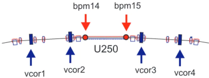
The beam stability at the storage ring Delta is affected by low frequency distortions during the ramp of our booster BoDo and beam oscillations caused by mains power sup- plies generating distortions with the frequency of 50 Hz and its harmonics up to approx. 350 Hz . Furthermore girder movements at their resonance frequencies, excited by ground vibrations, lead to displacements of magnetic el- ements of the accelerator, particularly the quadrupoles and therefore detoriate the photon beam stability at the beam lines. In order to supply higher brilliance synchrotron radi- ation a global fast orbit feedback is under consideration in connection with the existing slow orbit feedback working at frequencies at about 0.1 Hz . For this reason a local fast orbit feedback in the vertical plane (see Fig. 1) has been developed to prove the feasibility of the planned feedback and to test designated methods and components.
LOCAL ORBIT BUMPS
The dependency between the corrector strength θ
jat the corrector j and the orbit z
iat position i can be described
∗patryk.towalski@udo.edu
bpm14 bpm15
vcor1 vcor2 vcor3 vcor4
Figure 1: Setup of the vertical fast local orbit feedback at DELTA consisting of an undulator (U250), two beam posi- tion monitors (BPMs) and four vertical correctors (vcor).
using the orbit response matrix R : R
ij= ∂z
i∂θ
j(1)
The calculation of the expected orbit z can be achieved by superposing the effects of all corrector θ
j:
z = R θ. (2)
Using the technique of singular value decomposition (SVD) the calculation of a pseudoinverse is possible even if R is a singular matrix. The corrector strength θ
jfor given orbit z is then directly derived from the pseudoinverse R
+of the response matrix R via:
θ = R
+z. (3)
The vector z represents the required orbit, the vector θ represents the best approximation of the appropriate cor- rector strength to apply. Appropriate in the sense of being the best solution is achieved by the method of a least square fit. The superposition of two orbit bumps using four correc- tors allows for the adjustment of the orbit at bpm14 and 15.
The bumps are created with the correctors vcor1 to vcor4 (see Fig. 1) mounted at appropriate positions [3].
A response matrix R for all of the 54 BPMs and four correctors was measured with beam. In a next step the pseudoinverse of R was used to calculate the corrector co- efficients for the two orbit bumps using four correctors. Or- bit bump induced crosstalk between bpm14 and bpm15, as well as the influence on the orbit outside the feedback sec- tion was less then 10 % , verified at 7 control BPMs.
ORBIT DISTORTIONS
To identify the typical orbit distortions, a frequency spectrum was created from decimated turn-by-turn data MOPD13 Proceedings of DIPAC09, Basel, Switzerland
02 BPMs and Beam Stability
74
0 0,5 1 1,5 2 2,5 3 3,5 4
0 100 200 300 400 500 600 700 800
Amplitude [μm/√Hz]
Frequency [Hz]
Figure 2: Spectral rms orbit deviation versus frequency.
10−9 10−8 10−7 10−6 10−5 10−4 10−3 10−2 10−1
10 20 30 40 50 60 70 80 90
Displacement PSD [μm2/Hz]
Frequency [Hz]
Vertical (ground) Horizontal (quadrupole) Vertical (quadrupole)
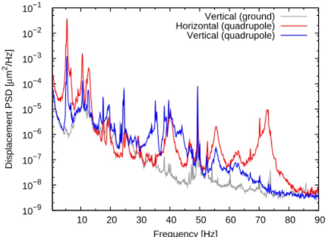
Figure 3: Displacement PSD horizontal and vertical on a quadrupol and vertical on the ground.
taken by an I-Tech Libera electronic [4] installed at bpm14.
The experimental results are shown in Fig. 2. Apart from distinctive distortions at 50 Hz and its harmonics, caused by the mains power supplies, low frequency perturbations in the range of 5 Hz have been observed.
Girder oscillation has been measured using geo- phones [5] during regular beam operation to identify the source of these low frequencies. One geophone capable to measure in three dimensions was attached to a quadrupole, a second one (measuring in one dimension) was mountend vertically on the floor. The geophones create a voltage pro- portional to the speed of their movement. This voltage was amplified and then recorded using a “LeCroy WaveSurfe 454” oscilloscope at a sampling frequency of 500 Hz .
MATLAB [6] was used to calculate the spectral power density (PSD), to apply a Hamming window function and to convert the velocity data to real displacement. Figure 3 shows the experimental results. Excitation frequencies of 5.3 Hz , 10.6 Hz and 12.5 Hz are caused by girder reso- nances. These oscillations lead to a time dependent trans- verse misalignment of the quadrupoles [7], influencing the orbit.
Config-RAM
MA PID
DCC BUMP RS485 BE548
correction_machine itest_be548 bump pid ma dcc
FFT
fft
Controller
rx_fifo tx_fifo
UART
control_unit
LEDs, Buttons, Switches Control-PC
RS 232
xup_feedback_top Libera BPM
Bergoz BPM
Bergoz BPM Libera BPM Libera BPM
S-ATAtoSFP RS485Interface Corrector
Corrector Corrector
Corrector
XUP-V2P Board
Tx Rx
Figure 4: Block diagramm of the correction system of the local fast orbit feedback implemented in VHDL.
IMPLEMENTATION OF THE LOCAL FAST ORBIT FEEDBACK SYSTEM
The fast local orbit correction has been implemented as a classic control loop. Each element of the loop can influence the control dynamics by delay or bandwidth.
The orbit position has been measured at bpm14 and 15 with I-Tech Libera Electron [4] BPMs, equipped with the Diamond Communication Controller allowing to distribute the fast orbit position data over a glas-fibre network at a rate of 10 kHz .
1The BPMs digital filters have a latency time of about 300 µs at a bandwidth of 2 kHz .
The data processing takes place on the Xilinx XUP- Virtex-II Pro Development Board [8], available through the Xilinx University Program. It is, similar to the I-Tech Liberas, equipped with a Virtex-II Pro FPGA. The cor- rection system was implemented using the hardware de- scription language VHDL. It is controllable using a con- nected standard-PC. The data processing is done in mod- ules, which can be seen in Fig. 4.
The position data sent to the network from bpm14 and bpm15 (see Fig. 1) is received from the Diamond Commu- nication Controller [DCC in Figure 4] in a first step. During a settable time window ( 60 µs in our case) received posi- tion data is passed to a moving average filter/low pass filter [MA]. In this way the dc-part and therefore the interfer- ence with the existing slow orbit correction is eliminated.
Calculation of the correction values is done by a standard proportional, integral and derivative controller [PID]. The D-fraction is set to zero to minimize the influence of data noise. In a next step the desired orbit is converted into corrector currents using equation (3) to create a superpos- tion of the two four corrector bumps [BUMP]. The new de- sired current values are converted into a serial data stream [RS485] and are distributed via the RS485 interface to the corrector magnet power supplies. The time for correction calculation on the board is approximately 0.2 µs and there- fore negligible.
The power supplies BE548 from the company iTest are
1Future plans include the connection of existing analog Bergoz BPMs into the fast orbit positition data network. For reference please see G.
Schuenemann [1].
Proceedings of DIPAC09, Basel, Switzerland MOPD13
02 BPMs and Beam Stability
75
−25
−20
−15
−10
−5 0 5 10
0 100 200 300 400 500 600
Frequency response [dB] at bpm14 and 15
Frequency [Hz]
bpm14 bpm15
Figure 5: Frequency response at bpm14 and 15.
used as four-quadrant power supplies ( ±24 V , ±10 A ).
They are connected to the four corrector magnets vcor1 to vcor4 (see Fig. 1 and 4). The minimum time delay after reception of new desired values is 40 µs . The additional delay to reach steady state depends on the desired current variation and the coils inductance. In our case 5 A can be applied in approx. 220 µs . This corresponds to a slew rate of 20833 kA/s .
The magnetic field of the corrector magnets varying in time induces eddy currents in the vacuum chamber. The frequency response was measured using an inductance coil inside the chamber. The vacuum chamber cut-off fre- quency (-3 dB) was estimated to 1.7 kHz .
The minimum latency for the control loop is about 400 µs resulting in a controller resonance frequency of about 1.25 kHz . Assuming oscillations with a current change of 5 A the total delay increases to 620 µs causing a shift of the resonance frequency of the control loop to 800 Hz .
Increasing this resonance frequency and thereby increas- ing the attainable cut-off frequency is in principle possible by further reducing the delay.
RESULTS
The frequency response being the ratio of distortion am- plitudes with and without orbit feedback was measured with beam at bpm14 and 15. The experimental results are shown in Fig. 5. The amplitude ratios have been deter- mined at strong distortion frequencies only, intermediate values have been interpolated linearly. The cut-off fre- quency at bpm14 turned out to be 355 Hz , bpm15 has a cut-off frequency of 370 Hz . A total damping of −20 dB at a frequency of 50 Hz has been obtained with the con- troller.
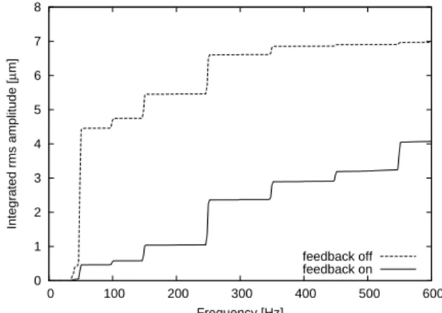
Figure 6 shows the integrated rms amplitude with and without orbit feedback obtained at bpm14 (averaging over multiple spectra). Due to strong intensity fluctuation of the girder movements in the lower frequency range the inte- grated rms amplitude would be spoiled by this random ef-
0 1 2 3 4 5 6 7 8
0 100 200 300 400 500 600
Integrated rms amplitude [μm]
Frequency [Hz]
feedback off feedback on