MBT and SRF
Energy Recovery from High Calorific Fractions by Incineration together with Sewage Sludge in the Fluidized Bed Furnace in Simmeringer Haide
Friedrich Kirnbauer and Stephan Kraft
1. Introduction ...316
2. Description of the fluidized bed incineration plant (WSO4) ...316
3. Operational experience ...319
4. Development of a 3D computational particle fluid dynamics model ...321
4.1. Description of computational particle fluid dynamics ...321
4.2. Project description ...322
4.3. Description of the reactor model including boundary conditions ...322
4.4. Description of the model for the fuels ...323
4.5. Validation of the model using operational data ...325
4.6. Optimization of the operation...326
5. Conclusion ...326
6. Literature ...327
A 39 MWth bubbling fluidized bed incinerator is in operation in Vienna since late 2003 to incinerate domestic waste and dewatered sludge. The demand is to cover a high range concerning calorific value from 5.5 MJ/kg to 11 MJ/kg depending on the fuel input. The plant is equipped with an electrostatic precipitator, a wet scrubber, ad- sorber and a Denox-plant. Operational experience shows that the plant suffers from inorganic fouling at the reactor walls of the oven with a high risk for the availability of the plant. To support optimization measures a research project was started to develop a three dimensional computational particle fluid dynamics model to locate areas of high fouling tendencies. This project includes the model development of the plant and the chemical reactions as well as the validation of the model. Furthermore, the model should be used to suggest optimized operation to reduce fouling tendencies and to reach higher availability.
MBT and SRF
1. Introduction
The municipal waste from Vienna is combusted at four different locations in the city area of Vienna: Spittelau, Flötzersteig, Pfaffenau and Simmeringer Haide. Municipal waste is incinerated using two different technologies: grate combustion and fluidized bed combustion. Since 1980, Wien Energie GmbH has been operating a plant to treat sewage sludge, liquid and solid waste, hazardous industrial and commercial waste, as well as hospital waste, in two rotary furnace lines and four fluidized-bed furnace lines at Simmeringer Haide, 11. Haidequerstraße 6, 1110 Vienna, to produce district heating.
To increase the capacity and flexibility of the plant site a 39 MWth (Rowitec design) bubbling fluidized bed (BFB) incinerator was built and started operation in October 2003. The fuels assigned for this incinerator are pre-treated domestic waste from mid to high heating value and dewatered sewage sludge as a reserve capacity for other three fluidized bed oven.
The expected advantage of the BFB incinerator was high fuel flexibility with lower NOx and CO emissions. BFB incinerators have the possibility to remove sulfur using lime stone addition in the bed material. Due to low temperatures in the bed (< 660 °C) low sintering and ash melting is expected. Inorganic matter can be steadily discharged and ferrous metal and aluminum can be recovered in an unoxidized state. The Rowitec design is characterized by the rotating fluidized bed where uneven distribution of the primary air over the distributor should cause an internally imposed circulation through the sand bed for higher fuel flexibility and also the discharge of coarse inor- ganic particles [12].
The BFB incinerator (named WSO4, fluidized bed oven #4) is designed to operate the bubbling fluidized bed in an understoichiometric regime while the fuel is dropped onto the fluidized bed. The temperature can be kept below the melting temperature of inorganic matter. Degasing of the fuel takes place in the fluidized bed and a part of the fuel is gasified and combusted. The injection of the secondary air provides the required oxygen for the complete combustion of the degassed fuel products. The injection of recirculated flue gas reduces the temperature in the head of the oven.
2. Description of the fluidized bed incineration plant (WSO4)
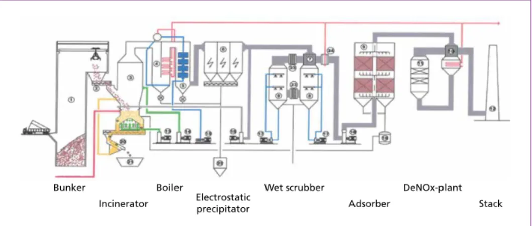
The basic flow sheet of the incineration line is shown in Figure 1. The fluidized bed incinerator is followed by a 3-pass boiler, an electrostatic precipitator, a 2-stage wet scrubber, a fixed bed activated carbon adsorber and a Denox-plant.
The incinerator is designed for waste combustion (design capacity of 12.5 t/h waste, net calorific value of 11 MJ/kg; mixtures of waste and spent activated carbon up to 15 MJ/kg) and co-combustion of waste and sewage sludge (3.5 t/h of waste and 15.3 t/h of de- watered sludge, net calorific value of the mixture 5.5 MJ/kg) and part-load operation down to 60 %.
MBT and SRF
After passing the pre-treatment steps of grinding, screening, partly ferrous metal separation, domestic waste is fed by crane and conveyed by two double screw feeders and dropped on the bed-surface through two chutes, both located on the same side of the incinerator. Sewage sludge enters the incinerator via four nozzles positioned right above the bed-surface, one on each side of the incinerator.
Bunker Boiler Wet scrubber DeNOx-plant
Stack Adsorber
Incinerator Electrostatic precipitator
Figure 1: Basic flow sheet of the incineration line
Source: Strauss, T.; Pröll, T.; Hofbauer, H.: Start up and operation optimization of a 39 MWth bubbling fluidized bed incinerator for domestic waste and sewage sludge. In: Proceedings of the 19th International Conference on Fluidized Bed Combustion. 2006, pp. 23-25
waste feeder
revolving fluidized bed
fluidising air
flue gas
deflector plate
non- combustibles discharge chute
Inclined nozzle plate
The dimensions of the rectangular bubbling bed are 8 x 4 m and the bed height is lower in the middle of the short bed side due to the roof shaped inclined gas distributor (Fi- gure 2). The primary air fan supplies fluidizing air to the different nozzle sections of the gas distributor via three main pipes and a number of wind boxes connected to the pipes.
Figure 2:
Rowitec design of the fluidized bed
Source: Lentjes
MBT and SRF
Bed material is discharged through four chutes, two on each side of the nozzle floor.
Coarse bottom ash is separated from the fine fraction using a sieving machine. The fine fraction which is mainly bed material is recycled back into the bed.
Above the bed low pressure recycle gas, taken from the outlet of the electrostatic precipitator, is introduced at two levels, for controlling the temperature at the head of the freeboard. The bed temperature can also be influenced by shifting recycle gas to the lower injection level and blowing more gas towards the bed. Excess oxygen is con- trolled by secondary air flow, which is introduced at two levels in the circular shaped freeboard area.
The incinerator is designed to be operated in bubbling mode with higher gas velocities at the outside area of the bed and lower velocities at the area above the rooftop of the grid. [11]
The bed is operated in an understoichiometric regime. Bed temperature is tried to be kept around 630 °C during waste incineration, while full combustion is achieved in the freeboard area. The set point of the temperature at the top of the freeboard is 930 °C to fulfill the demand of the authorities (Temperature > 850 °C).
The design data for the fuels are shown in Table 1. Oil fractions are required only for temperature controlling reasons and heat up. Activated carbon can be used as a fuel to dispose it from flue gas cleaning from all incineration lines at the location.
Table 1: Design data for fuel input
Fuel Parameter Unit Design Range
Throughput t/h 12 < 16
Municipal Lower heating value kJ/kg 11,000 8,000 – 15,000
solid waste Water content % 20 10 – 30
Ash content % 20 10 – 30
Throughput t/h db 6.84 < 6.84
Dewatered Dry substance % 36 20 – 45
sewage Organic dry substance % 68 45 – 80
sludge Hygroscopic water in the dry substance % 4.5 1 – 5 Heating value of the organic dry substance kJ/kg 23,000 22,000 – 24,000 Heavy Throughput t/h db < 500
heating oil lower heating value kJ/kg 40,200 Waste oil Throughput t/h db < 500
lower heating value kJ/kg 37,000 Heating oil
(extra light) Lower heating value kJ/kg 42,700
Activated Throughput t/h db < 1,500
carbon Lower heating value kJ/kg 26,500
Source: Strauss, T.; Krobath, P.: Wirbelschichtofen zur Verbrennung von Klärschlamm und Ersatzbrennstoff. In: Thomé- Kozmiensky, K. J.: Optimierung der Abfallverbrennung 1. Neuruppin: TK Verlag Karl Thomé-Kozmiensky, 2004, pp. 401-442
MBT and SRF
Parameter Unit Value
Pressure live steam bar abs 54 Temperature live steam °C 354 Maximum steam production t/h 49.5 Maximum temperature after oven °C 1,050 Ash content in the flue gas g/Nm³ 40 Flue gas temperature after boiler
at the beginning of the operation °C 180 Flue gas temperature after boiler
before shut down °C 210
The design data of the boiler are shown in Table 2. Steam is converted in electricity and district heat in steam turbines where steam from all boilers at the plant site is collected.
Table 2:
Design data of the boiler
Source: Strauss, T.; Krobath, P.: Wir- belschichtofen zur Verbrennung von Klärschlamm und Ersatzbrennstoff. In:
Thomé-Kozmiensky, K. J.: Optimierung der Abfallverbrennung 1. Neuruppin: TK Verlag Karl Thomé-Kozmiensky, 2004, pp. 401-442
3. Operational experience
The oven is designed to incinerate around 100.000 t MSW per year, which is reached.
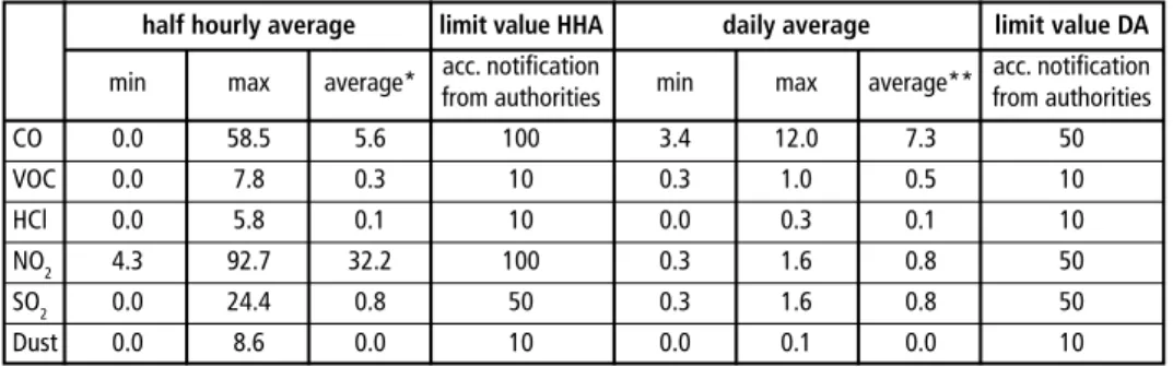
Emission limits are achieved and partly undercut significantly (Table 3). Nevertheless, the operation suffers from a reduced availability due to inorganic fouling at reactor walls in the area of the freeboard and on the top of the reactor close to the entry to the boiler. This fouling appears to fall down into the fluidized bed and also in the boiler area with the risk of defluidization of the fluidized bed, plugging conveyors and sieving equipment. This results in higher costs for maintenance and service. The typical crys- tal structure of this inorganic fouling is shown in Table 4 and shows that aluminum compounds play a dominant role. Aluminum in an unoxidized state is considered to be responsible for fouling. Aluminum is considered to be oxidized at the reactor walls during operation forming hard fouling.
Table 3: Air emission data at the stack WSO4 in the year 2016 Air emissions, continuous measurement – WSO4 2016
Values corrected for reference conditions in mg/m3, 11 % O2, dry, with subtraction of confidence intervals. No correction to 11 % oxygen is made for values with O2 < 11 %
half hourly average limit value HHA daily average limit value DA min max average* acc. notification
min max average** acc. notification
from authorities from authorities
CO 0.0 58.5 5.6 100 3.4 12.0 7.3 50
VOC 0.0 7.8 0.3 10 0.3 1.0 0.5 10
HCl 0.0 5.8 0.1 10 0.0 0.3 0.1 10
NO2 4.3 92.7 32.2 100 0.3 1.6 0.8 50
SO2 0.0 24.4 0.8 50 0.3 1.6 0.8 50
Dust 0.0 8.6 0.0 10 0.0 0.1 0.0 10
* arithmetic average of HHA ** monthly average calculated with operating hours, amount of flue gas and pollutants
MBT and SRF
Measures were started to decrease inorganic based fouling at the reactor walls and its damage since 2013. A cleaning device was developed to remove fouling during ope- ration using water balls which evaporate when they slam at the fouling surface. This evaporation and the thermal stress at the fouling removes the fouling with only little impact on the availability compared to cooling off the reactor. The damage at the re- fractory lining is low compared to the mechanical stress during cooling off the reactor and mechanical removing of the fouling.
Additionally, primary measures are planned to reduce fouling tendencies. Operational conditions that increase the risk for fouling are high temperatures, areas of low oxygen content due to bad gas mixing and areas of high velocities in the reactor. The primary measures include following points: 1. Reduction of the maximum temperatures in the oven, 2. Reduce gas velocities and discharge of inorganic matter from the fluidized bed These measures aim to increase the availability of the oven, increase the fuel flexibi- lity, reduce the amount of additional fuels (different oil fractions) and CO2 emissions additionally, and reduce the maintenance costs.
A rebuild of the air staging which is carried out in autumn 2017 will reduce the gas velocities in the area of the fuel input by around half. This includes the implementa- tion of flue gas in the primary air which will bring more flexibility for the operation of the fluidized bed especially with high calorific waste. On the other hand during sludge combustion flue gas in the primary air reduces the bed temperature which is not required so the amount of flue gas should be reduced to a minimum during sludge combustion. This leads to the conclusion that the implementation of flue gas in the primary air should be realized with an operational range from zero to the maximum of the recycled flue gas blower.
On the other hand, the implementation of recycled flue gas to cool the freeboard tem- perature will be relocated on the height of the first secondary air nozzles. The control strategy will be the following: bed temperature is controlled by the split between recir- culated flue gas and primary air flow in the fluidization gas. The flow of fluidization gas will be kept constant depending on the particle size distribution of the bed material.
The recycled flue gas implemented in the height of the secondary air is used to control the head temperature of the oven. The amount of secondary air is controlled by the excess oxygen in the flue gas.
Crystal structure Formula Unit SH2016-061 Corundium α-Al2O3 % 64.0 Hercynite FeAl2O4 % 13.3 Diopside CaMg(SiO3)2 % 5.2
Aluminium Al % 4.7
Gehlenite Ca2Al2SiO7 % 3.8 Akermanite Ca2MgSi2O7 % 2.9
Silicon Si % 2.6
Quarz SiO2 % 1.8
Hematite Fe3O4 % 1.7
Table 4:
Example for the crystal compo- sition of the fouling
MBT and SRF
These measures are assisted by the development of a 3D computational particle fluid dynamics (CPFD) simulation model for the incineration of waste and sludge in coope- ration with the competence center Bioenergy 2020+ GmbH and TU Wien.
4. Development of a 3D computational particle fluid dynamics model
A research project is ongoing to build up a three dimensional computational particle fluid dynamics model and validate the model at the WSO4. It is carried out supported by mass and energy balances to detect operation modes with the high risk of fouling and to locate the area of fouling. The exact location of fouling often cannot be detected clearly because fouling comes loose during cool down of the oven.
4.1. Description of computational particle fluid dynamics
For the simulation the commercial tool Barracuda is used. In Barracuda the MP-PIC (multi-phase particle-in-cell) approach is used to simulate gas-solid flows. The gas phase is calculated as an Eulerian or continuous phase. The particle phase is descri- bed in a discrete or Lagrangian way and uses mean values from the Eulerian mesh to significantly reduce computational cost. Therefore, Barracuda allows simulating large industrial vessels and is used in the present study for simulating the 39 MWth incinerator.
Barracuda also allows the implementation of reacting particles as well as homogene- ous gas phase chemistry which is especially necessary for the simulation of reacting combustion flows as investigated in this study. Therefore, the mixing behavior of fuel particles in the fluidized bed can be investigated and zones of high temperatures with higher risk of deposit build-up can be identified, as e.g. successfully demonstrated by Kraft et al. [5].
In the following the basic equations of the MP-PIC implementation as used in Bar- racuda are given. More details can be found in Snider [8] and Snider et al. [9]. The continuity and momentum equation for the gas phase is expressed as:
∂(εgrg)
+
.
(εgrgurg) = dmp (1)∂t
∂(εgρgug)
+
.
(εgρgugug) =- p + F + εgρgg +.
(εgτg) (2)∂t
For the particulate phase a Liouville equation is solved using a particle distribution function f:
∂f +
.
(fup) + (up) (fap) = 0 (3)∂t
D D
D D
D D
.
MBT and SRF
The mass production δmp is also described using f:
δmp= –
∫∫∫
f (dmp)dmpdu-pdTp (4)
dt
The acceleration of the particles at low particle volume fractions is calculated as:
ap = Dp(ug – up) – 1 p + g – 1 τ ρp єpρp (5)
Dp is the drag function, the other terms represent the static pressure gradient, gravity, and the interparticle stress.
The interphase momentum exchange rate F is also related with the particle distribution function f:
F = –
∫∫∫
f{
mp[
CD (ug – up) – 1p
]
+updmp
}
dmpdupdTp (6)ρp dt
4.2. Project description
The research project is divided into 4 steps. First, the reactor geometry is drawn and applied in Barracuda. Based on the geometry the boundary conditions such as gas inlets, fuel feeding and outlets are implemented. In a second step literature is reviewed to find suitable reaction kinetics to model the release and combustion of the volatiles as well as the combustion of the remaining (solid) char. Furthermore, operation data is checked for plausibility via mass and energy balance calculations which also provide the data for the boundary conditions in the Barracuda simulation.
Then the validation of the model is carried out by selecting 5 representing ope- rational modes of the incinerator and comparison of measurements and simula- tion results. In the last step the validated model is used to optimize the process to minimize the formation of deposits as well as to obtain an even fuel mixing within the bubbling bed.
4.3. Description of the reactor model including boundary conditions
The geometry of the reactor including boundary conditions is shown in Figure 3. The bed is fluidized by bottom air. The two legs on the right and left side of the bottom air are used in operation for bed material discharge which is not simulated. For bed coo- ling flue gas is recirculated and blown onto the fluidized bed in two stages. The sewage sludge is fed into the reactor via 4 nozzles, for waste two chutes are used. To maximize the burn-out of not fully oxidized gas components two additional air inlets are used (primary and secondary air). Finally, the flue gas leaves the reactor at the flue gas outlet.
. .
D D
D
→ → →
MBT and SRF
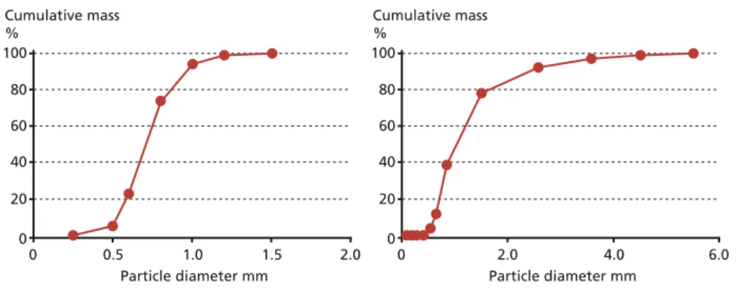
Figure 4: Particle size distribution of fresh sand (left) and used bed material (right) after operation
4.4. Description of the model for the fuels
In the simulations the following fuels are used: waste, sewage sludge, and different oil species.
Waste and sewage sludge particles consist of the following pseudo-components:
• Moisture: water which is released while the fuel is dried
• Volatiles: released during the heat-up by thermal break-up of the bonds of the longer hydrocarbon molecules
Flue gas outlet
Secondary air
Primary air Recirculated flue gas
Bottom air Sewage sludge Waste
Figure 3: Geometry and boundary conditions of the reactor
The bed material amount was chosen to cause a pressure drop over the bed of 90 mbar which is a typical value reached in operation. Since bed material is diluted with inorganic material such as glass and ceramics from the waste different operati- on stages of the bed material are simulated:
fresh quartz sand and diluted quartz sand with a different particle size distribution.
Figure 4, (a) and (b), shows the particle size distribution of the fresh sand and the bed material after operation. It can be seen that the mean particle diameter increases of approximately 0.75 mm to over 1 mm.
Such changes in the size of the bed material can lead to a significant change of mixing behavior of the much larger and lighter fuel particles [6].
100 80 60 40 20
Cumulative mass
%
Particle diameter mm
00 0.5 1.0 1.5 2.0
100 80 60 40 20
Particle diameter mm
00 2.0 4.0 6.0
Cumulative mass
%
MBT and SRF
• Organic char: the organic solid residue if moisture and volatiles are released
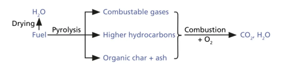
• Ash: does not participate in the reactions and sums up all the inert materials The volatiles are further divided into combustible gases (CO, CO2, H2, H2O, and CH4) and higher hydrocarbons which lumps together all the other (condensable) gaseous organic components. In the present simulation C2H4 and C2H6 are used to simulate these components.
Figure 5 shows the reaction mechanism for the waste and sewage sludge particles. In the first step the particle dries (at 100 °C) and the moisture is released as gaseous H2O.
Then the particle is further heated up and thermal breakage of the hydrocarbons occurs.
The combustible gases and higher hydrocarbons are released. A solid residue consis- ting of the organic char and the inert ash remains. In a further combustion step all the aforementioned pseudo-components burn with O2 to the final combustion products CO2 and H2O. In the simulation the amount of sulfur is not considered and also the formation of NOx because of the negligible effects on the hydrodynamics in the system.
Combustable gases
Combustion + O2 Pyrolysis
Drying
Higher hydrocarbons
Fuel CO2, H2O
H2O
Organic char + ash
Figure 5: Reaction mechanism of the combustion of the fuel particles (waste and sewage sludge) The oil droplets are treated a bit differently, Figure 6. When fed into the system the liquid droplets (oil(l)) are evaporated where the moisture of the oil (H2O) and the gase- ous oil (oil(g)) are released. The gaseous oil then burns with O2 to the final combustion products CO2 and H2O.
H2O
Oil(g) Oil(l) Evaporation
Combustion
+ O2 CO2, H2O
Figure 6: Reaction scheme of the combustion of the oil droplets
For all the reactions (drying, release of volatiles, and combustion) an Arrhenius ap- proach is used:
k = k0exp
(
– Ea)
(7)RTp
MBT and SRF
with k0 as the pre-exponential factor, Ea as the activation energy, R the molar gas con- stant and Tp the particle temperature.
For sewage sludge and waste the drying is modeled with the approach by Chan et al. [1]. The pyrolysis for the sewage sludge particles is modeled with the kinetic data by Shie et al. [7], for the waste particles the kinetics by Cozzani et al. [2] are used. The combustion of the oil is modeled with the kinetics published by Gawade et al. [3].
The combustion of CO, H2, CH4 are modelled with the kinetics used by Groppi et al. [4] and the combustion of the higher hydrocarbons (C2H4, C2H6) are modelled with the kinetics by Van der Vaart [13] and Zimont and Trushin [14].
4.5. Validation of the model using operational data
For the validation of the simulation model 3 to 5 operational points are chosen which represent typical operational modes of the incinerator. First, the operational data are checked by mass and energy balance calculations which then act as reliable input for the Barracuda simulations.
For the hot plant temperature measurements are available which also act as validation of the simulation model. Temperatures are a measure for the energy release in the reactor and therefore, can be used to check the plausibility and applicability of the combustion kinetics.
First results of the calculations are shown in Figure 7. The lower part of the waste incinerator is shown including the bubbling fluidized bed.
The particles are colored according to the particle volume fraction. Red particles repre- sent particles in a packed volume fraction. Yellow to green particles show a more dilute
Particles VolFrac
Splash zone
bubbling bed 0.6
0.5
0.4
0.3
0.2
0.1
0
Figure 7:
Particle volume fraction of the fluidized bed
MBT and SRF
flow with a particle volume fraction between which is typical for bubbling fluidized beds.
The bubbling bed can be clearly seen in Figure 7 as well as the characteristic splash zone over the bed where the bubbles burst. The particles in the two legs occur in the close pack regime, since they are not fluidized.
4.6. Optimization of the operation
Using the validated CPFD model an operation point should be found where deposits due to ash melting are minimized and the mixing of the fuel in the bed is maximized.
The following ways of optimization are investigated regarding their impact on the aforementioned objectives:
• Optimization of the primary air supply for improvement of the mixing of the par- ticles in the fluidized bed
• Variation of the velocity and the mass flow rates, respectively, in the air nozzles
• Variation of the mass flows in the inlets for the secondary air and recirculated flue gas
Doing so, Barracuda is used to calculate temperature profiles to identify local zones where the ash melting temperature is exceeded. Furthermore, the distribution of the fuel in the bubbling bed is simulated as well as the concentration of the gas species within the incinerator.
5. Conclusion
The BFB waste incineration plant from Vienna is successfully in operation since 2003 and reaches good operational results. Changes in the energy market and developments in the waste market demand higher availability and higher fuel flexibility. Fouling at reactor walls are the most challenging issues. Therefore, new tools are developed to analyze and to optimize the process. Robust results of these optimization measures are expected to be seen within the next years.
Nomenclature
symbol meaning SI units
ap particle acceleration m/s²
Dp drag function 1/s
Ea activation energy J/mol
f probability distribution function for particulate phase [–]
F rate of momentum exchange kg/(m² s²)
g gravity m/s²
MBT and SRF
k reaction rate mol/(m³ s)
k0 pre-exponential factor dependent
δmp gas mass production rate per volume kg/(s m³)
mp particle mass kg
p pressure Pa
R universal gas constant J/(mol K)
t time s
Tp particle temperature K
ug velocity of gas phase m/s
up velocity of particle phase m/s
εg gas volume fraction [–]
εp particle volume fraction [–]
ρg gas density kg/m³
ρp particle density kg/m³
τg interparticle stress Pa
6. Literature
[1] Chan, W.; Kelbon, M.; Krieger, B.: Modelling and experimental verification of physical and chemical processes during pyrolysis of a large biomass particle, Fuel, 64, 1985, 1505-1513 [2] Cozzani, V.; Nicolella, C.; Petarca, L.; Rovatti, M.; Tognotti, L.: A Fundamental Study on Con-
ventional Pyrolysis of a Refuse-Derived Fuel. Industrial & Engineering Chemistry Research, 34, 1995, 2006-2020
[3] Gawade, P.; Patel, D.; Lipscomb, G.; Abraham, M.: Kinetics and Modeling of the Flexible Fuel Reformer: n-Hexadecane Steam Reforming and Combustion. Industrial & Engineering Che- mistry Research, 2010, 49, 6931-6940
[4] Groppi, G.; Tronconi, E.; Forzatti, P.; Berg, M.: Mathematical modelling of catalytic combustors fuelled by gasified biomasses. Catalysis Today, 59, 2000, 151-162
[5] Kraft, S.; Kuba, M.; Kirnbauer, F.; Bosch, K.; Hofbauer, H.: Optimization of a 50 MW bubbling fluidized bed biomass combustion chamber by means of computational particle fluid dynamics.
Biomass and Bioenergy, 89, 2016, pp. 31-39
[6] Rowe, P.; Nienow, A.; Agbim, A.: The mechanisms by which particles segregate in gas fluidised beds - binary systems of near-spherical particles. Transactions of the Institution of Chemical Engineers, 50, 1972, 310-323
[7] Shie, J.; Chang, C.; Lin, J.; Wu, C.; Lee, D.: Resources recovery of oil sludge by pyrolysis: kinetics study. Journal of Chemical Technology and Biotechnology, 75, 2000, 443-450
[8] Snider, D.: An incompressible three-dimensional Multi-Phase Particle-in-Cell model for dense particle flows. Journal of Computational Physics, 170, 2001, pp. 523-549
[9] Snider, D.; Clark, S.; O’Rourke, P.: Eulerian-Lagrangian method for three-dimensional thermal reacting flow with application to coal gasifiers. Chemical Engineering Science, 66, 2011, 1285- 1295
MBT and SRF
[10] Strauss, T.; Krobath, P.: Wirbelschichtofen zur Verbrennung von Klärschlamm und Ersatzbrenn- stoff. In: Thomé-Kozmiensky, K. J.: Optimierung der Abfallverbrennung 1. Neuruppin: TK Ver- lag Karl Thomé-Kozmiensky, 2004, pp. 401-442
[11] Strauss, T.; Pröll, T.; Hofbauer, H.: Start up and operation optimization of a 39 MWth bubbling fluidized bed incinerator for domestic waste and sewage sludge. In: Proceedings of the 19th International Conference on Fluidized Bed Combustion. 2006, pp. 23-25
[12] Van Caneghem, J.; Brems, A.; Lievens, P.; Block, C.; Billen, P.; Vermeulen, I.; Dewil, R.; Baeyens, J.; Vandecasteele, C.: Fluidized bed waste incinerators: Design, operational and environmental issues, Progress in Energy and Combustion Science, Volume 38, Issue 4. 2012, pp. 551-582; ISSN 0360-1285, http://dx.doi.org/10.1016/j.pecs.2012.03.001
[13] Van der Vaart, D.R.: The combustion of gas in a fluidized bed. PhD Thesis, University of Cam- bridge, England, 1985
[14] Zimont, V.L.; Trushin, Y.M.: Total combustion kinetics of hydrocarbon fuels, Combustion, Ex- plosion, and Shock Waves, 5, 1969, 567-573
Bibliografische Information der Deutschen Nationalbibliothek Die Deutsche Nationalbibliothek verzeichnet diese Publikation in der Deutschen Nationalbibliografie; detaillierte bibliografische Daten sind im Internet über http://dnb.dnb.de abrufbar
Thomé-Kozmiensky, K. J.; Thiel, S.; Thomé-Kozmiensky, E.;
Winter, F.; Juchelková, D. (Eds.): Waste Management, Volume 7 – Waste-to-Energy – ISBN 978-3-944310-37-4 TK Verlag Karl Thomé-Kozmiensky
Copyright: Elisabeth Thomé-Kozmiensky, M.Sc., Dr.-Ing. Stephanie Thiel All rights reserved
Publisher: TK Verlag Karl Thomé-Kozmiensky • Neuruppin 2017
Editorial office: Dr.-Ing. Stephanie Thiel, Elisabeth Thomé-Kozmiensky, M. Sc.
Janin Burbott-Seidel and Claudia Naumann-Deppe
Layout: Sandra Peters, Anne Kuhlo, Ginette Teske, Claudia Naumann-Deppe, Janin Burbott-Seidel, Gabi Spiegel and Cordula Müller
Printing: Universal Medien GmbH, Munich
This work is protected by copyright. The rights founded by this, particularly those of translation, reprinting, lecturing, extraction of illustrations and tables, broadcasting, micro- filming or reproduction by other means and storing in a retrieval system, remain reserved, even for exploitation only of excerpts. Reproduction of this work or of part of this work, also in individual cases, is only permissible within the limits of the legal provisions of the copyright law of the Federal Republic of Germany from 9 September 1965 in the currently valid revision. There is a fundamental duty to pay for this. Infringements are subject to the penal provisions of the copyright law.
The repeating of commonly used names, trade names, goods descriptions etc. in this work does not permit, even without specific mention, the assumption that such names are to be considered free under the terms of the law concerning goods descriptions and trade mark protection and can thus be used by anyone.
Should reference be made in this work, directly or indirectly, to laws, regulations or guide- lines, e.g. DIN, VDI, VDE, VGB, or these are quoted from, then the publisher cannot ac- cept any guarantee for correctness, completeness or currency. It is recommended to refer to the complete regulations or guidelines in their currently valid versions if required for ones own work.