Dorfstraße 51
D-16816 Nietwerder-Neuruppin
Tel. +49.3391-45.45-0 • Fax +49.3391-45.45-10 E-Mail: tkverlag@vivis.de
Order now: www. .de
TK Verlag Karl Thomé-Kozmiensky
– with the focus on waste incineration facilities –
This comprehensive text and practical handbook thoroughly presents the control of air pollutant emissions from combustion processes focusing on waste incinerators. Special characteristics are emphasised and the differences to emission control from combustion processes with other fuels are explained.
The author illustrates the origin and effects of air pollutants from incineration processes, the mechanics of their appearance in the incineration process, primary and secondary measures for their reduction, processes of measuring the emissions as well as the methods of disposing the residues. In particular, the pros and cons of procedual steps and their appropriate combination under various conditions are emphasised.
Moreover, the book contains information and analyses of the emissions situation, the consumption of operating materials and of backlog quantities as well as of the cost structure of waste incinerators with regard to their applied control system.
Furthermore, the author explicates the contemporary legal, scientific and technological developments and their influence on air pollutant emission control. An evaluation of the status quo of air pollutant control at waste incinerators in Germany, practical examples about possible combinations and typical performance data complete the content.
Accordingly, this book is a guideline for planing a reasonable overall concept of an air pollutant control that takes the location and the segregation tasks into consideration. This book is addressed to students, decision makers, planners and the operating practicioners if for example the construction of a new system or the implementation of improvement measures have to be conducted.
Released: August 2017 120.00 EUR
Emissions and Emission Monitoring
340 Fixed mirror
Focussing mirror Beam splitter
with compensator
Moving mirror
Light source Gas sample Gas sample Collimator
Detector Sample cell
Figure 242: Measurement principle of an FTIR multi-component spectrometer with a Michelson interferometer setup
Source:
TÜV Süd Industrie Service GmbH, UBA-Texte 05/08, adapted
splitter where they are brought together to interfere with each another in intensity as they recombine. Depending on the mirror displacement, the interference may be constructive (increasing) or destructive (decreasing). When using polychromatic light, the interference occurs for each wave length so that the interference intensities of the individual wave lengths superpose one another [369].
of the target component and are directed by a focusing mirror to an infrared detector is computed from the recorded interferogram (intensity at detector as a function of mirror displacement) by mathematical Fourier transformation. For quantitative eva- luation, the calculated infrared spectrum is compared with a reference spectrum [380].
An alternative to the Michelson interferometer is the vibration-insensitive RockSolid arrangement [356].
9.2.3.3.2 Multi-component measurement by non-dispersive infrared spectroscopy Non-dispersive infrared (NDIR) spectroscopy is based on the absorption of an in- frared spectrum wavelength that is unique to the gaseous component to be detected.
In contrast with dispersive infrared spectroscopy, non-dispersive methods do not spectroscopy is applicable to multi-component analysis, i.e. the simultaneous analysis of several emission parameters, and is frequently also used for raw gas measurements.
detector Light source Sample cell Calibration filter
Lens Detector
Filter wheels Chopper
Figure 243: Measurement principle of a multi-component NDIR spectrometer with heated sample gas cell Source: Boneß, M.: Messsysteme und Analysatoren zur kontinuierlichen Prozesskontrolle und Emissionsüberwachung in und Betrieb von Anlagen, Vol. 1, pp. 527–538. Neuruppin: TK Verlag, 2010 As infrared detectors can only detect changes in the infrared radiation, they require a modulated (pulsed) infrared source that is temporarily interrupted by a mechanical
component and selects the spectral region of its absorption band. If several gas com- ponents are to be analysed, chopper wheels covering several infrared spectral regions to calculate the gas concentration, which requires a concentration-independent refer- ence signal for comparison. For this purpose, NDIR analysers may be equipped with absorption band of the analysed component (bi-frequency technique). Alternatively,
.
Continuous Emission Monitoring
Also available in German!
50.00 EUR
Author: Margit Löschau • Publisher: TK Verlag Karl Thomé-Kozmiensky • Hardcover: about 480 pages, numerous coloured images
Flue Gas Treatment
SNCR Technology
to Meet Challenging NO
xReduction Requirements
Wolfgang Schüttenhelm and Philip Reynolds
1. State-of-the-art ...392
2. Challenging NOx reduction ...394
3. Dual injection SNCR technology ...397
4. Improved monitoring and control ...400
4.1. Plausibility check ...401
4.2. Online check of the measured value drift ...401
4.3. Online calorific value ...401
4.4. Fractionation ...402
5. Profitability...402
6. Flexibility or simplification? ...403
7. Conclusion ...404
8. Literature ...405
NOx reduction by means of SNCR-Technology is continuously developing to increase its performance potential. This ongoing development is based on more and more sophisticated control concepts, modified hardware and software as well as improved designs. Consequently, increased requirements in respect to higher levels of process safety, increased reliability of mechanical components, better efficiency of the injected reduction agents as well as higher degree of automation are achieved.
This paper addresses ERC’s most recent developments of the SNCR technology.
Today, this well-proven denitrification process is able to meet even very challenging requirements due to the combination of new control concepts with new and improved injection processes.
As already described in [1] new emission limits for NOx and NH3 are set in the German 17. BImSchV for waste-to-energy plants. In detail, daily average limits of 150 mg/Nm3 NOx and 10 mg/Nm3 NH3 at actual O2 content are to be met for new and existing waste- to-energy units of more than > 50 MW thermal capacity from 01.01.2019.
Flue Gas Treatment
Many existing units are equipped with SNCR meeting the more moderate existing limits of today. These units have been able to safely comply and these more relaxed requirements could be fulfilled with the typical deviating combustion conditions of waste-to-energy plants. However, the new more stringent limits are requesting much more flexible SNCR solutions to provide the same safe operation. Thus, adaptions, modifications and upgrades are necessary for many units in order to cover the whole operational range of fuels and loads. The set of measures usually has to be determined for each individual plant due to different site conditions, firing systems as well as local requirements and factors. Potential measures, impacts and concepts will be presented to show efficient and high performance modernization solutions of SNCR installations.
Of course, modernization requires new investments. However, such measures are also increasing the efficient use of the reduction agent which at least is going to compensate for a part of the spent costs. Besides, longer boiler running times and/or load increases can be a part of the measures which might even turn the expenses into a benefit after a short time period.
1. State-of-the-art
The NOx reduction by Selective Non Catalytic Reaction (SNCR) is next to the Selective Catalytic Reaction the most common way to reduce NOx in flue gas.
A reduction agent is mixed with water for distribution, atomized by compressed air and sprayed by lances into the flue gas. Urea or ammonia are common reduction agents.
The amount of reduction agent is controlled by the resulting NOx reduction which is measured by means of the NOx emission measurement system. Most components of the SNCR system are located in so-called mixing and dosing modules adjusting the flows to the injection lances. These lances have to be arranged in a way to provide a very good distribution of the reduction agent in the boiler cross section within the required reaction temperature range. Moreover, sufficient reaction time is required to achieve an optimum NOx reduction with minimum NH3 slip at the same time.
The basics of the SNCR technology are well-known [1]. Furthermore, sample projects have already been presented demonstrating that 100 mg/Nm3tr. NOx together with 10 mg/Nm3 had been met in a first phase of developments of the SNCR Technology [6]. The introduction of online temperature measurement systems has been a very important step forward. Existing units are requiring a case-by-case analysis to engineer the best possible process and components improving the plant’s denitrification in order to meet the new targets of 150 mg/Nm3 NOx and 10 mg/Nm3 NH3.
The following impacting parameters have to be analysed and evaluated when develo- ping a new SNCR concept:
• Temperature at the injection points
• Impact of the boiler running time to the temperature profile
• Variation of the fuel heating value including seasonal variation of humidity in waste
Flue Gas Treatment
• NOx raw gas concentration including their range
• Retention/reaction time for the SNCR reaction
• CO levels in the injection zone
• Load variations
• Distribution of the reduction agent
• Distance of the injection levels
• Instrumentation and control of the SNCR
• Type of reduction agent
Figure 1 is showing a sample of NOx reduction and NH3 slip depending on flue gas temperature for a given flue gas composition. The NOx control efficiency is increasing up to an optimum temperature of about 980 °C. At higher temperatures, the NOx re- duction is decreasing due to the increased side reaction of oxidizing ammonia instead of reacting with NOx. On the other hand the ammonia slip is decreasing with higher temperatures. At very high temperatures, NH3 is oxidized and N2 or even more NOx is formed. Figure 1 also shows the older and actual temperature design range to meet even challenging NOx reduction limits as well as the new ammonia limit of 10 mg/Nm3. Since there was no ammonia slip limit defined in Germany before 2016 it was possible to inject the reduction agent in a very wide temperature range of about 850 °C to 1,095 °C.
Usually, one active injection level was sufficient in order to meet the required moderate NOx reduction level. The load had to be slightly reduced at the end of the boiler running period in order to reduce the temperature at the injection level. The new limits and even locally lower NOx emission limits are requiring an improved NOx reduction. Therefore, the lower SNCR temperature limit needs to be increased to limit the slip and the upper SNCR temperature limit needs to be reduced to achieve the higher NOx reduction.
100
80 90
70 60 50 40 30 20 10 0 NOX Reduction
%
NH3 Slip mg/m3 20
16
12
8
4
0
750 850 950 1,050 1,150
Reaction Temperature °C operatingnew
range
old operating range
Figure 1:
NOx reduction and NH3 slip depending on temperature, former and new SNCR design base
Flue Gas Treatment
In order to meet the 150 mg/Nm3 NOx limit the permitted operational temperature is ranging from about 930 °C to 1,075 °C. The new temperature range being shown in Figure 1 is even more restricted since it shows a very challenging NOx reduction effici- ency of about 75 %. Please note that these temperature windows have to be adapted for special plants in order to take the available residence time and other constraints such as residual CO contents into consideration.
Consequently, the reduction of the permitted SNCR temperature operational range is influencing the denitrification result, the SNCR design and firing system operation as well as the achievable boiler running time. Usually, more injection levels and modified controls of the injections are required, see also [1] and [5]. In case of a non-ideal initial design of the original SNCR the distance between the levels has to be reduced in order to also reduce temperature imbalances between injection levels and to switch the lances as close as possible to the optimum SNCR operational temperature.
Much more care has to be taken to consider impacts of load changes, differences in fuel composition and heating value as well as oxygen distribution. Especially, the fast varying heating value of the waste requires new SNCR control concepts as well as a more sophisticated novel approach of the SNCR design.
Besides temperature deviations, larger deviations of primary NOx emissions result in increased emissions of NH3 and clean gas NOx. Conventional SNCR control schemes are based on the comparison of actual to target NOx clean gas value. Thus, it is a backwards orientated control always requiring to measure the result of the denitrification. Deviations of the raw gas NOx-content cannot be taken into consideration. Therefore, such deviations of the raw gas NOx – either produced by higher N-content of the waste or due to more primary NOx production – are another source of not meeting stringent emission limits.
To sum up, the new emission limits require a modified approach and a very careful pro- cess design. The mentioned conflict between matching a narrower SNCR temperature range despite high temperatures at high loads at the end of the boiler running time is worth a detailed analysis and upgrades of non-flexible SNCR installations. Respective conventional samples are presented in [4].
2. Challenging NO
xreduction
All operators of waste-to-energy plants are focusing on burning waste and producing energy while minimising operating and maintenance cost. Providing ideal conditions for SNCR operation is of secondary importance. How to define Challenging NOx Re- duction in case of a thermal waste treatment facility?
In chapter 2 the main factors are listed in details which are important to achieve high NOx reduction with low ammonia slip. An even more detailed overview is described in [2].
As far as these factors such as temperature window, residence time, fast response to deviating fuel and combustion conditions cannot be controlled in a proper way the results will substantially differ from the requested performance level. Therefore, it is a challenge to design a system which is able to overcome those obstacles.
Flue Gas Treatment
Besides, the following items are often monitored in waste-to-energy plants resulting in not meeting the constraints laid down in chapter 2 being required for a high efficient denitrification:
• Deviating heating value of the fuel,
• Large seasonal differences of the waste composition including humidity,
• Fast slagging of the first boiler pass,
• Fast changing loads,
• Insufficient burn-out,
• Strong temperature imbalances,
• Non-adjusted firing control system.
The result of challenging conditions can be graphically shown by means of the so-called scale. The measured values of NH3 and NOx downstream of the SNCR are reverse pro- portional to each other. While trying to improve one of them by means of adjustments this will result in an increase of the other emission value. Figure 2 shows a sample for 100 mg/Nm3 NOx and 10 mg/Nm3. The axis of the diagram are scaled in a way that the limits of both pollutants NOx und NH3 are on the same horizontal line. As soon as the intersecting points are meeting in another horizontal line above the limits-line it is a challenging NOx reduction system. If the NOx-concentration is reduced below the limit-line by means of adding more reduction agent, the ammonia slip is immediately increasing above its limit. As a reaction of the control system the reduction agent flow will be reduced to meet the ammonia slip limit, however, resulting in a fast increase of the NOx concentration above the NOx limit.
Unfortunately, the average values are not adjustable in a more appropriate way in such cases due to limitations of the installed SNCR process and its controls. Consequently, only one emission limit will be met in average and it has to be accepted that the other one is above its limit.
0 5 10 15 20
0 50 100 150 200
NH3 mg/Nm3 NOx
mg/Nm3
Scale for insufficient denitrification
NOx mg/Nm3 NH3 mg/Nm3
Figure 2:
Schematic showing the balance between NOx and NH3 values during insufficient denitrifica- tion above 100 mg/Nm3 NOx and 10 mg/Nm3 NH3
Flue Gas Treatment
As a result of such analysis the only solution is a modification of the SNCR. Flexibility and more reduction potential below the limits are required to lower the actual line of the intersection points below the level of the limit-line. ERC Technik GmbH developed respective solutions covering also such challenging NOx reduction issues.
Improving NOx reduction has to be the target in order to lower the intersection-line below the limit-line, Figure 3.
0 5 10 15 20
0 50 100 150 200
Scale for a good denitrification NH3 mg/Nm3 NOx
mg/Nm3
NOx in mg/Nm3 NH3 in mg/Nm3
Figure 3:
Schematic showing the balance between NOx and NH3 values during good denitrification below 100 mg/Nm3 NOx and 10 mg/Nm3 NH3
Figure 4 shows a SNCR Mixing and Metering module of a standard denitrification.
Figure 4:
Standard mixing and metering module
Flue Gas Treatment
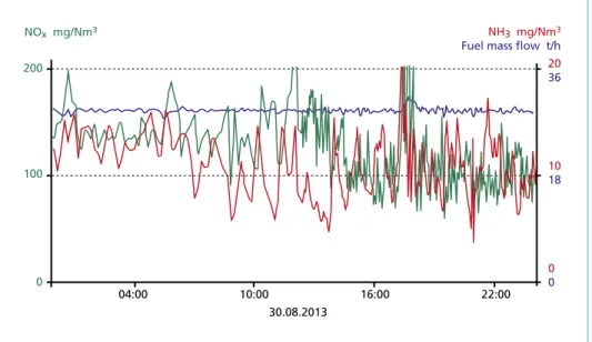
Figure 5 shows the result of a standard denitrification SNCR before installing a novel Dual Injection SNCR system. It can be recognized that the average values of the NOx and NH3 curves are above the respective limits of this sample 100 mg/Nm3 NOx and 10 mg/Nm3 NH3. If one of those values is decreasing below its limit the respective other limit is increasing above this limit.
NOx mg/Nm3 NH3 mg/Nm3
Fuel mass flow t/h 200
100
0
20 36
10 18
0
10:00 16:00 22:00 0
04:00
30.08.2013
Figure 5: Insufficient NOx reduction before SNCR refurbishment – scale above limit values
3. Dual injection SNCR technology
In order to increase flexibility and provide process margins ERC Technik developed its Dual Injection SNCR process. The amount of reduction agent is calculated and it is injected by means of those levels which are above and below the optimum SNCR operation temperature.
The Dual Injection process is based on the following principle:
The first reaction step is taking place at higher temperatures. Thus, there is very limited risk of slip production. The amount of reduction agent to the first level is serving for a pre-removal of NOx. However, the temperature at this first level is too high to meet the required total NOx reduction. Therefore, a second reaction stage is located just upstream of the first level showing a lower temperature being close to the optimum SNCR temperature. Usually, the NOx reduction efficiency is somewhat higher compared to the first stage. However, at this lower temperature there is a tendency to emit more ammonia being necessary to limit the NOx reduction efficiency of this level below the maximum one. Figure 6 shows both reaction stages within the SNCR temperature window diagram and explains the process of the Dual Injection system.
Flue Gas Treatment
It is expected that larger and more recently installed waste-to-energy plants are not necessarily requiring this Dual Injection technology to meet the new German emission limit of 150 mg/Nm3 NOx in combination with 10 mg/Nm3 NH3. In most of such cases these plants are having larger cross sections with reduced flow velocities in the first boiler pass. Consequently, their burn-out is very good, disturbing CO concentrations are low and the retention time for the SNCR reaction is long enough to achieve a very good performance. However, the new Dual Injection technology has been proven as been very effective for boilers targeting even lower emissions such as 100 mg/Nm3 NOx combined with 10 mg/Nm3 NH3. Moreover, the Dual Injection technology is applicable for smaller boilers operating with high flue gas speeds and very often at overload. In some cases this novel technology was the only successful process to solve a very chal- lenging NOx reduction problem.
100
80 90
70 60 50 40 30 20 10 0 NOX Reduction
%
NH3 Slip mg/m3 20
16
12
8
4
0
750 850 950
Reaction Temperature °C
reaction zone 2 reaction zone 1
1,050 1,150
Figure 6:
SNCR reaction window, dual injection
Altogether, the amount of reduction agent of this process is similar or even below the reduction agent amount of a single stage injection being secured by means of a special controller.
The total amount of reduction agent is de- termined by means of the NOx-difference across both stages. The result of the Dual Injection system is significantly improved in comparison to the less flexible single stage injection systems.
All injection levels are designed and arranged in a comparable way to the con- ventional single stage process. Therefore, it is not mandatory to install a second level of lances just below an existing level.
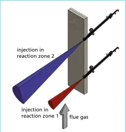
injection in reaction zone 2
injection in
reaction zone 1 flue gas
Figure 7: Schematically lance arrangement, dual injection SNCR
Flue Gas Treatment
It is more important to achieve a better coverage of the boiler’s cross section by means of arranging of the lances in an appropriate way to react to the temperature profiles.
Figure 7 presents a schematic arrangement of a Dual Injection system.
Figure 8 shows the mixing and metering module of a Dual Injection SNCR after re- furbishment of the original single stage SNCR. It is arranged close to the mixing and metering module of the former single stage process as shown in Figure 4.
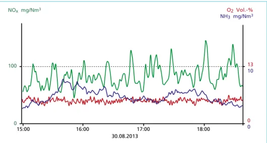
Figure 9 shows the result of the refurbished system with Dual Injection System employ- ing the new module, Figure 8. The NOx reduction is clearly improved. Both limits NOx and NH3 are met. The intersection line is arranged below the limit-line of NOx und NH3.
Figure 8:
Mixing and metering module after modification to dual injec- tion SNCR
NOx mg/Nm3 O2 Vol.-%
NH3 mg/Nm3
100
0
13 10
0
16:00 17:00 18:00 0
15:00
30.08.2013
Figure 9: Good NOx reduction after dual injection SNCR refurbishment – scale below limit values
Flue Gas Treatment
4. Improved monitoring and control
As shown in chapter 2, the control of the SNCR, more precisely the control of the reduction agent’s quantity, is of decisive importance for the quality of the real process.
The quality of the control depends on the type of control parameters as well as on the speed with which it can be used. Thus, for example, the value of the load respectively of the steam production, as still used in some old systems, is entirely unsuitable to control the SNCR. In fact, the control has to be depend on absolutely current values of temperature, flue gas amount and NOx content.
Proven systems are available to measure the temperature as well as the flue gas quantity.
These correspond to the technical standard.
The NOx raw gas value is required in order to adjust the quantity of reduction agent.
However, this value cannot be measured prior to the SNCR. Therefore, in case of a classical SNCR control, the quantity of reduction agent is controlled according to the deviation of the result of the denitrification from the set point. In this case, the nitrogen measurement provides the NOx pure gas value. Indeed, the delay of the SNCR process to the pure gas measurement became apparently disadvantageous when tightening the limit values. A NOx measuring unit can be installed behind the combustion chamber in the cooler temperature range to reduce the dead time. Moreover, it is also possible to install a NH3 measuring unit. By means of contemporary measured values of NH3 or NOx behind the boiler the SNCR can be controlled precisely due to the fact that the dead time is drastically reduced. Several plants are already controlled in such a way.
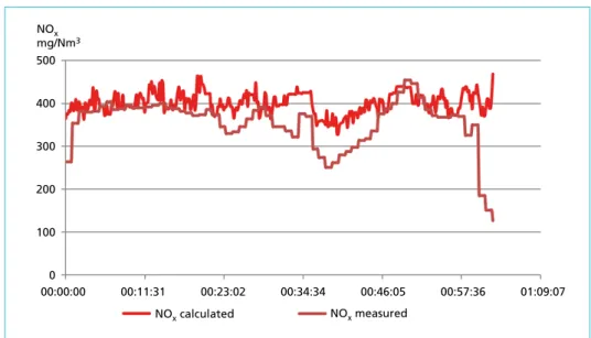
If such measurements are not available, the Opti-Link system can be used [2]. The NOx raw gas value can be calculated by balancing of measured energy and material flows and can be used for the contemporary control of reduction agent’s quantity. If the SNCR is switched off during a test, the calculated and measured value for NOx can be directly compared. Figure 10 shows both values in comparison.
NOx mg/Nm3 500
400
300
200
100
0
NOx calculated NOx measured
00:00:00 00:11:31 00:23:02 00:34:34 00:46:05 00:57:36 01:09:07
Figure 10: NOx raw gas value, measured and calculated via Opti-Link
Flue Gas Treatment
A measured value is preferable in case it is used for control only and provided the measurement is sufficiently accurate.
Furthermore, the benefits of balancing the NOx-value are additionally based on other positive side-effects [3]. Through this arise advantages which also take effect if one measuring unit is installed directly downstream of the boiler.
4.1. Plausibility check
A plausibility check can be used to determine whether the indicated measured values are correct. If there are large differences within the balances after recalculation, at least one of the measuring units must be incorrectly calibrated or the conversion factor programmed at commissioning is not accurate.
4.2. Online check of the measured value drift
If online monitoring is carried out within the system according to the principle of the plausibility check, the drift of the measuring devices can be monitored. Thus, the system indicates whether one of the measuring instruments operates outside the permissible tolerance range.
4.3. Online calorific value
fuel mass flow t/h
calorific value MJ/kg
time
time 25
20 15 10 5 0
25 20
15
10 5
0
mass balance study (online balancing) indicated value
energy balance (with fuel mass flow indicated value)
energy balance (with online mass balance study) calorific value
formula
Figure 11: Fuel mass flow and calorific value over period of time
Flue Gas Treatment
Opti-Link allows the extraction of those parameters from the balancing, which cannot be measured with measuring instruments contemporarily or with difficulties only. Besides the NOx raw gas value, this also applies to the calorific value of the combusting waste.
The calculation of the calorific value is carried out without the input of the crane scale.
It is immediately generated from available values and, thus, is actually available online.
Figure 11 shows the fuel mass flow and calorific value over a period of time. The dotted lines illustrate the values indicated in the control room, including in its calculation time-delayed values of the crane scale. The solid lines are derived from the balancing.
4.4. Fractionation
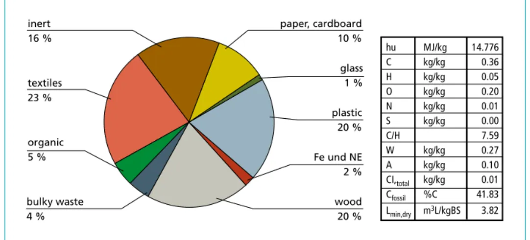
To determine the NOx raw gas value, the fractionation of the waste is first approxima- ted. It may be interesting for the operator to record the data on the composition of the waste over the annual course. Figure 12 shows a calculated fractionation of the waste combusted during the calculation period.
paper, cardboard 10 %
textiles 23 %
plastic 20 %
wood 20 % organic
5 % inert 16 %
bulky waste 4 %
Fe und NE 2 % glass 1 %
hu MJ/kg 14.776
C kg/kg 0.36
H kg/kg 0.05
O kg/kg 0.20
N kg/kg 0.01
S kg/kg 0.00
C/H 7.59
W kg/kg 0.27
A kg/kg 0.10
CI,total kg/kg 0.01
Cfossil %C 41.83
Lmin,dry m3L/kgBS 3.82
Figure 12: Examplary Waste Fractionation
5. Profitability
Figure 13 shows the temperature of the flue gas at the last injection level as well as the steam load at a continuous operating period. It can be clearly seen that the load has to be lowered at the end of the operating period in order to obtain the required tem- perature for denitrification. In such a case an extension of the plant by an additional level and the Opti-Link with dual injection is profitable in two aspects. Firstly, the load can be kept constant over the entire operating period so that the waste incineration plant can process constant amounts of waste at any time. Secondly, the efficiency of the denitrification is improved, i.e. reduction agents can be reduced by up to twenty percent based on the new limit values.
Flue Gas Treatment Figure 13: Temperature and load during continuous operating period
A further advantage of upgrading the plant with the Opti-Link is the detection of possible measurement errors during the O2 measurement due to the plausibility check as well as the online drift detection. Even small deviations of the O2 value cause high amounts of additional flue gases and, thus, an overall energy efficiency loss.
6. Flexibility or simplification?
The more the mentioned parameters of a combustion vary, the higher the degree of flexibility of the SNCR has to be. Consequently, the quality of the input parameters increases, too.
Opti-Link and Dual Injection as well as a detailed investigation of the incineration plant’s operation [4] continue to pursue this direction.
The tendency must therefore clearly lead to thorough analysis and flexible high-per- formance SNCR systems, which will cope with every situation. The reduction of the temperature window as shown in Figure 1 requires that, due to the more complicated conditions, the optimum ranges are accurately hit, NOx flue gas values are contem- porarily recorded or the raw gas value is calculated.
Sometimes attempts are being made to save expenses in improved plant technology in order to reduce the initial investment costs. However, in such cases the effects of devi- ations of the conditions in the combustion chamber are from time to time substantial
time (00:00:00) 01.07.1301.08.1
3
01.09.1301.10.1301.11.1301.12.1301.01.1401.02.1401.03.1401.04.1401.05.1401.06.1401.07.1 4 1,000
900
800
700
600 60.0
52.5
45.0
37.5
30.0
∆ Load
T ≈ const.
Temperature
°C Load
t/h steam
Flue Gas Treatment
and cannot be treated without limiting operation of the boiler. Indeed, the NH3 slip can be excessively high and/or the consumption of the reduction agent also increases significantly.
The knowledge and use of the characteristic of the atomization is a fundamental com- ponent of a successful denitrification concept. Easier more simple injection systems are only limitedly successful.
7. Conclusion
By using technologies that increase the degree of detailing and flexibility, the challenges of denitrification can be overcome.
A modern SNCR is able to use the best possible reaction areas which can be reliably detected by means of sophisticated analytics.
Gaps in the analysis can now be concluded with special calculation algorithms. The calculated parameters are directly incorporated into the control of the SNCR. As a result the SNCR is resistant against occurring fluctuations. Using Opti-Link, it is also possible to calculate parameters required to standardize the combustion control sys- tem. Thus, the conditions for a denitrification are improved and the operator is given further advantages due to a steadied operation.
The plausibility check of the measured values and the control of the measured value drift means safety for the operator since he can protect himself against false measured values and their consequences.
The novel Dual Injection process significantly increases the process stability of the SNCR. The different, adapted concentrations in the double denitrification provide excellent denitrification results. The additional constructional effort required for this technology is limited to a few additional fittings. In most cases the injection can be effected on layers being necessary for covering the occurring temperature fluctuations anyway.
The combination of the processes ensures the sustainability of the SNCR beyond the new limit values.
Non-flexible SNCR systems must necessarily fail if the parameters of the combustion system are not kept absolutely constant. It was shown that the necessary complexity of the SNCR system depends on the conditions of the combustion, the required limit values as well as the permitted consumption rates. Simplified plant concepts often ignore this context. In the end the operator of an incineration plant does not save anything when purchasing a cheap SNCR as the money saved is quickly spent due to a more expensive operation of the plant. In addition, less income is generated during the subsequent operating period.
Thus, the investment into an optimized SNCR pays off for the operator, since the optimal use of reduction agents, lower maintenance costs and the extension of the operating period lead to increased profits.
Flue Gas Treatment
8. Literature
[1] Hukriede, J.; Pachaly, R.; Reynolds, P.: Neue 17. BImschV – Auswirkungen auf bestehende Ab- fallverbrennungsanlagen mit SNCR-Technik sowie Lösungskonzepte. In: Thomé-Kozmiensky, K. J.; Beckmann, M. (eds.): Energie aus Abfall, Band 11. Neuruppin: TK Verlag Karl Thomé- Kozmiensky, 2014, pp. 559-574
[2] Pohl, M.: Vom Brennstoff zum Rauchgas über Combustion 4.0. In: Kraftwerkstechnik 2015.
Freiberg: Saxonia, 2015, pp. 367-375
[3] Reynolds, P.: Günther, C.: Technisches und wirtschaftliches Potential der Online-Bilanzierung.
In: Thomé-Kozmiensky, K. J.; Beckmann, M. (eds.): Energie aus Abfall, Band 13. Neuruppin:
TK Verlag Karl Thomé-Kozmiensky, 2016, pp. 303-316
[4] Schüttenhelm, W.; Reynolds, P.: SNCR for Low NOx Emissions – Case Study of a Swedish Waste- to-Energy plant. In: Waste managment. Neuruppin: TK Verlag Karl Thomé Kozmiensky, 2015, pp. 221-236
[5] Schüttenhelm, W.; Reynolds, P.; Hukriede, J.: Einhaltung verschärfter NOx- und NH3-Grenzwerte bei bestehenden Anlagen – Vorgehen und Lösungsansätze anhand von Praxisbeispielen. [book auth.] Karl J. Thomé-Kozmiensky and Michael Beckmann. Energie aus Abfall, Band 12. Neu- ruppin: TK Verlag Karl Thomé-Kozmiensky, 2015, 373-390
[6] Tappe, T.: Feuerraumdiagnose und SNCR-Optimierung in einem EBS Kraftwerk. Potsdam:
Potsdamer Fachtagung, 2011
Dorfstraße 51
D-16816 Nietwerder-Neuruppin
Tel. +49.3391-45.45-0 • Fax +49.3391-45.45-10
E-Mail: tkverlag@vivis.de TK Verlag Karl Thomé-Kozmiensky
Order now: www. .de
Immission Control
(Nullpunktreflektor
und Dunkelblende) Reflektor
Schwenksegement Nullzyklus (Nullpunktreflektor und Dunkelblende)Schwenksegement Nullzyklus (Nullpunktreflektor
(Nullpunktreflektor
, ThielIMMISSIONSSCHUTZ
4
Thomé-Kozmiensky • Löschau
K.J. Thomé-Kozmiensky Michael Hoppenberg
IMMISSIONSSCHUTZ
– Planung, Genehmigung und Betrieb von Anlagen – Band 1
1
Thomé-Kozmiensky, Hoppenberg , ThielIMMISSIONSSCHUTZ
4
Thomé-Kozmiensky • Löschau
Karl Joachim Thomé-Kozmiensky Matthias Dombert
Wolfgang Rotard Markus Appel
Andrea Versteyl
IMMISSIONSSCHUTZ
– Planung, Genehmigung und Betrieb von Anlagen – Band 2
2
Thomé-Kozmiensky Dombert, V
ersteyl, Rotard, Appel , ThielIMMISSIONSSCHUTZ
4
Thomé-Kozmiensky • Löschau
K.J. Thomé-Kozmiensky Stephanie Thiel
Markus Appel Andrea Versteyl
Wolfgang Rotard
IMMISSIONSSCHUTZ
– Aktuelle Entwicklungen im anlagenbezogenen Planungsprozess und Immissionsschutz
Band 3
3
Thomé-Kozmiensky Versteyl, Thiel, Rotard, Appel , Thiel
IMMISSIONSSCHUTZ
Recht – Anlagenbetrieb – Optimierung – Emission K. J. Thomé-Kozmiensky Margit Löschau
Band 4
IMMISSIONSSCHUTZ
4
Thomé-Kozmiensky • Löschau , Thiel
IMMISSIONSSCHUTZ
Recht – Umsetzung – Messung – Emissionsminderung K. J. Thomé-Kozmiensky Margit Löschau
Band 5
IMMISSIONSSCHUTZ
4
Thomé-Kozmiensky • Löschau
5
Michael Boneß
123
Messung
Tabelle 1:
Störkomponente Konzentration QE auf die Hg-Messung
SO2 1.000 mg/m2 – 0,065 µg/m3
H2O 30 Vol.-% 0,060 µg/m3
HCI 200 mg/m3 keine QE
NO 300 mg/m3 keine QE
NO2 30 mg/m3 0,090 µg/m3
O2 21 Vol.-% – 0,120 µg/m3
Alle weiteren getesteten QE‘s < ± 0,05 µg/m3
5. Anwendungsbereich des neuen Messverfahrens für die Emissions- und Prozessmessung bei Verbrennungsanlagen Emission
Das neue Messverfahren konnte bereits für die Emissionsüberwachung des Gesamt- anlagen) ohne Leistungseinbußen oder Einschränkungen erfolgreich absolviert.
Für den Standardmessbereich von 0 bis 45 µg/m³ gilt an allen drei Anlagen ein War- tungsintervall von sechs Monaten.
Prozess (Rohgasanwendung)
Aufgrund der einfachen Bauweise und der Gasentnahme ohne zusätzliche Hilfs- und Re- Die Resultate der Testinstallationen zeigen hierbei die Flexibilität des eingesetzten Messver- fahrens, sowohl für den kleinsten Messbereich von 0 bis 10 µg/Nm³, als auch bis in den sehr hohen Konzentrationsbereich von bis zu 4.000 µg/m³ (Bild 10). Eine schnelle, zuverlässige möglich, wieder rot markierte Peak zeigt (Bild 11). Das Messsystem kommt dabei unverän- dert gegenüber der Emissionsmesseinrichtung zum Einsatz und ermöglicht dem Betreiber bzw. unbekannter Zusammensetzung. Im vorliegenden Beispiel an einer kommunalen Hausmüllverbrennungsanlage betrug die Grundlast im Durchschnitt etwa 200 µg/Nm³.
Allerdings traten auch immer wieder Spitzen von bis zu 3.000 bis 4.000 µg/m³ auf, was natürlich entsprechende Maßnahmen für die Gasreinigung, um den Grenzwert von des markierten Peaks verdeutlicht die schnelle Reaktionszeit der Messung sowohl im Anstieg, als auch im Abklingen der Hg-Konzentration (Bild 12).
Sowohl bei Abfallverbrennungsanlagen und insbesondere auch bei Sondermüllver- brennungsanlagen ist das Interesse an diesen Messungen sehr gestiegen. Denn mit der Hg-Rohgasmessung verfügt der Betreiber über eine Überwachung, die zum frühestmög- lichen Zeitpunkt eine mögliche Überladung von Hg für die Abgaswäsche signalisiert und Raum für Gegenmaßnahmen lässt.
124 Messung von Quecksilber
Messung
typischerweise durch SO2 und andere Gaskomponenten bekannt sind, treten bei diesem Verfahren nicht auf (Tabelle 1). Vergleichende Messungen an Anlagen mit bestehenden Quecksilber CEMS zeigen eine hervorragende Übereinstimmung, ebenso im Vergleich zu Optional können für die regelmäßige Qualitätskontrolle der Messungen automatisiert HgCl2-Konzentrationen über eine integrierte Verdampferapparatur aufgegeben werden.
Ejector Messgaszelle 1.000 °C Optik/Detektor Klimagerät Kalibriergas-generator (ohne Abdeckung)
blau= Untergrundmessung;
orange= Hg-Absorptionsmessung Hg-Linienaufspaltung durch Magnetfeld an der Lichtquelle Bild 7: Schrankansicht des kontinuierlichen Quecksilber-Messverfahrens MERCEM300Z (außen und innen)
Bild 8: Zeeman-AAS Messprinzip Bild 9:
Quarzmessgaszelle bei 1.000 °C zur Konvertierung und gleich- zeitigen Echtzeitmessung (pa- tentiert)
Immissionsschutz, Volume 1 Released: 2010
ISBN: 978-3-935317-59-7 Hardcover: 632 pages Price: 30.00 EUR
Immissionsschutz, Volume 2 Released: 2011
ISBN: 978-3-935317-75-7 Hardcover: 593 pages Price: 30.00 EUR
Immissionsschutz, Volume 3 Released: 2012
ISBN: 978-3-935317-90-0 Hardcover: 664 pages Price: 40.00 EUR Immissionsschutz, Volume 4
Released: 2014
ISBN: 978-3-944310-16-9 Hardcover: 450 pages Price: 50.00 EUR
Package Price
Immissionsschutz, Volume 1 – 5
150.00 EUR
save 80.00 EUR Immissionsschutz, Volume 5
Released: 2015
ISBN: 978-3-944310-23-7 Hardcover: 370 pages Price: 80.00 EUR
Editors: Karl J. Thomé-Kozmiensky et al. • Publisher: TK Verlag Karl Thomé-Kozmiensky
Bibliografische Information der Deutschen Nationalbibliothek Die Deutsche Nationalbibliothek verzeichnet diese Publikation in der Deutschen Nationalbibliografie; detaillierte bibliografische Daten sind im Internet über http://dnb.dnb.de abrufbar
Thomé-Kozmiensky, K. J.; Thiel, S.; Thomé-Kozmiensky, E.;
Winter, F.; Juchelková, D. (Eds.): Waste Management, Volume 7 – Waste-to-Energy – ISBN 978-3-944310-37-4 TK Verlag Karl Thomé-Kozmiensky
Copyright: Elisabeth Thomé-Kozmiensky, M.Sc., Dr.-Ing. Stephanie Thiel All rights reserved
Publisher: TK Verlag Karl Thomé-Kozmiensky • Neuruppin 2017
Editorial office: Dr.-Ing. Stephanie Thiel, Elisabeth Thomé-Kozmiensky, M. Sc.
Janin Burbott-Seidel and Claudia Naumann-Deppe
Layout: Sandra Peters, Anne Kuhlo, Ginette Teske, Claudia Naumann-Deppe, Janin Burbott-Seidel, Gabi Spiegel and Cordula Müller
Printing: Universal Medien GmbH, Munich
This work is protected by copyright. The rights founded by this, particularly those of translation, reprinting, lecturing, extraction of illustrations and tables, broadcasting, micro- filming or reproduction by other means and storing in a retrieval system, remain reserved, even for exploitation only of excerpts. Reproduction of this work or of part of this work, also in individual cases, is only permissible within the limits of the legal provisions of the copyright law of the Federal Republic of Germany from 9 September 1965 in the currently valid revision. There is a fundamental duty to pay for this. Infringements are subject to the penal provisions of the copyright law.
The repeating of commonly used names, trade names, goods descriptions etc. in this work does not permit, even without specific mention, the assumption that such names are to be considered free under the terms of the law concerning goods descriptions and trade mark protection and can thus be used by anyone.
Should reference be made in this work, directly or indirectly, to laws, regulations or guide- lines, e.g. DIN, VDI, VDE, VGB, or these are quoted from, then the publisher cannot ac- cept any guarantee for correctness, completeness or currency. It is recommended to refer to the complete regulations or guidelines in their currently valid versions if required for ones own work.