Proceedings 2018, 2, 1124; doi:10.3390/IECC_2018-05259 www.mdpi.com/journal/proceedings
Proceedings
Single Crystal X-ray Structure Analyses of Thallides:
Halide Incorporation and Mixed Alkali Sites in A 8 Tl 11 X (A = K, Rb, Cs; X = Cl, Br) †
Stefanie Gärtner
1,2,* and Susanne Tiefenthaler
11
Institute of Inorganic Chemistry, University of Regensburg, 93040 Regensburg, Germany;
susanne.tiefenthaler@ur.de
2
Central Analytics (X-Ray Dept.), University of Regensburg, 93040 Regensburg, Germany
* Correspondence: stefanie.gaertner@ur.de; Tel.: +49-941-943-4446
† Presented at the 1st International Electronic Conference on Crystals, 21–31 May 2018. Available online:
https://sciforum.net/conference/IECC_2018.
Published: 21 May 2018
Abstract: A
8Tl
11(A = alkali metal) compounds have been known since the investigations of Corbett et al. in 1995 and still are matter of current discussions as the compound includes one extra electron referred to the charge of the Tl
117−cluster. Attempts to substitute the charge by incorporation of a halide atom succeeded for the lightest homologue of the group, Cs
8Ga
11Cl, and powder diffraction experiments for the heavier homologues also suggested the formation of analogous compounds.
However, X-ray single crystal studies on A
8Tl
11X to prove this substitution and to provide a deeper insight into the influence on the thallide substructure have not yet been performed, probably due to severe absorption combined with air and moisture sensitivity for this class of compounds. In our contribution we present single crystal X-ray analyses of the new compounds Cs
8Tl
11Cl
0.8, Cs
8Tl
11Br
0.9and Cs
5Rb
3Tl
11Cl
0.5. It is shown that a (partial) incorporation of halide can also be indirectly determined by examination of the Tl-Tl distances for low resolved data sets, e.g., for Cs
5.7K
2.3Tl
11Cl
?. Mixed occupied sites by two different alkali metals indicate a dependence on the cesium content, the systems K/Rb–Tl–Br and K/Rb–Tl–Cl only gave rise to the formation of the higher reduced (K/Rb)
8Tl
11and the less reduced by-product (K/Rb)
15Tl
27. We have not been able to prove the formation of halide including thallides in the absence of cesium.
Keywords: thallides; X-ray structure analysis; intermetallics
1. Introduction
The largest (empty) thallide cluster is represented by the Tl
117−cluster which is present in binary materials A
8Tl
11[1,2] and A
15Tl
27[3] (A = K, Rb, Cs). The A
8Tr
11structure type was first described in 1991 for the lighter homologue indium in K
8In
11, [1,4] of which the crystal structure proved the presence of a naked, pentacapped trigonal prismatic shaped In
11cluster, which was assigned a charge of −7. Additionally, one extra-electron per formula unit is present, which is responsible for the metallic character. The additional electron, referred to the charge of −7 of the cluster anion, is not necessary for the stability of the clusters [5] and can be replaced by halide atoms, which are located on a 3 void (Wyckoff position 6b) at the origin of the unit cell resulting in a diamagnetic character of the compounds. Halide incorporation was proven for the lighter homologue of the group, Cs
8Ga
11Cl by X-ray single crystal structure analysis. [6] Powder diffraction experiments suggested the formation of the heavier homologues Rb
8Ga
11Cl, Cs
8Ga
11X (X = Br, I), Rb
8In
11Cl, Cs
8In
11Cl, Cs
8Tl
11X (X
= Cl, Br, I). The formation of Rb
8Tl
11Cl was termed as doubtful due to the lack of a significant change
in the lattice constants compared to Rb
8Tl
11.
The questions we wanted to answer were: (1) How does the geometry of the thallide cluster change on halide incorporation; (2) Is there a Rb
8Tl
11Cl?; (3) How do mixed cation sites affect the amount of halide incorporation?
In Section 2 (Results) we report on the first single crystal X-ray structure determination of halide including thallides, Cs
8Tl
11Cl
0.8, Cs
8Tl
11Br
0.9, Cs
5Rb
3Tl
11Cl
0.5and Cs
5.7K
2.3Tl
11Cl
?.Subsequently, (Section 3, Discussions) the crystal structures are investigated according to the questions listed above.
2. Results
All compounds crystallize in a variant of the K
8In
11structure type (rhombohedral, spacegroup R3c) and especially for the mixed alkali metal compounds, many of the crystals happened to form typical “multicrystals”. Due to the presence of reverse/obverse twinning a R(obv) filter was applied during data reduction. The materials naturally possess very high absorption coefficients (μ > 60 mm
−1), therefore small single crystals have been chosen for the X-ray analyses. However, the data sets still suffer from severe absorption effects which could be reduced by carefully applying numerical absorption correction (including refinement of A and B factors). Thereby, the adjustment of the correct shape played a dominant role. Table 1 lists selected data for the structure determination. For the chloride including compounds two additional, unresolved but several times reproduced residual electron density peaks (≈1.5 Å beside the chlorine atom, ≈2.2 Å beside cesium;
along the c-axis) are present, which we attribute to unresolved absorption effects as this direction is along the thinnest direction of the plate like crystals. For the bromine including compound this effect is not as dominant as for the chlorine including ones but still is observed.
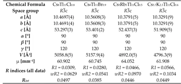
Table 1. Selected data reduction and refinement details.
Chemical Formula Cs
8Tl
11Cl
0.8Cs
8Tl
11Br
0.9Cs
5Rb
3Tl
11Cl
0.5Cs
5.7K
2.3Tl
11Cl
0.6Space group R3c R3c R3c R3c
a [Å] 10.4697(4) 10.5608(3) 10.3791(5) 10.3291(9) b [Å] 10.4691(4) 10.5608(3) 10.3791(5) 10.3291(9) c [Å] 53.297(3) 53.401(2) 52.437(3) 51.909(5)
α [°] 90 90 90 90
β [°] 90 90 90 90
γ [°] 120 120 120 120
V [Å
3] 5058.8(5) 5157.9(4) 4892.0(5) 4796.3(9) μ [mm
−1] 60.902 60.745 64.052 61.908 R indices (all data) R1 = 0.0309,
wR2 = 0.0629
R1 = 0.0280, wR2 = 0.0541
R1 = 0.0466, wR2 = 0.0970
R1 = 0.0566, wR2 = 0.1034
R
int0.0497 0.0385 0.0446 0.0449
With only one cation being present in the Cs
8Tl
11Cl
0.8and Cs
8Tl
11Br
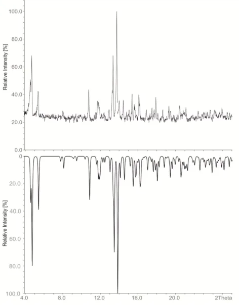
0.9, phase pure materials could be obtained according to the powder diffraction pattern of the bulk material (refined cell contstants at room temperature for Cs
8Tl
11Cl
0.8: a = 10.566(5), c = 53.67(3), R3c, 17 single indexed lines, Figure 1). Additionally the unit cells were checked for several single crystals which confirmed phase pureness.
The quality of the crystals is significantly improved for Cs
8Tl
11X compared to the mixed alkali
metal compounds, and in these cases we were able to obtain better resolved data which allowed for
the determination of split positions of one alkali metal according to the site occupany factor (s.o.f.) of
the halide atom. For the reported single crystals with mixed alkali metal positions the data quality is
worse compared to Cs
8Tl
11X phases, therefore the splitting of the alkali metal position could not be
observed due to the lower resolution of the data sets. In this case, we refined the s.o.f. of the halide
and for Cs
5Rb
3Tl
11Cl
0.5this resulted in an improvement of the F
o/F
calcratio and the residual electron
density, therefore we consider the value of 0.50(4) to be true. In contrast, the same treatment of the
halide in the data set of Cs
5.7K
2.3Tl
11Cl
0.6(refined s.o.f.: 0.60(4)) did not allow for a significant
improvement of the model, therefore the amount of halide incorporation cannot be determined reliably in this case, but the s.o.f. value of the halogen atom fits the s.o.f. for Cs amount of the split position.
Figure 1. Powder diffraction patterns of Cs
8Tl
11Cl
0.8: Measured (top) and calculated (bottom;
calculated from single crystal data of Cs
8Tl
11Cl
0.8).
3. Discussion
3.1. How Does the Geometry of the Thallide Cluster Change on Halide Incorporation?
All A
8Tl
11and A
8Tl
11X
xcompounds include Tl
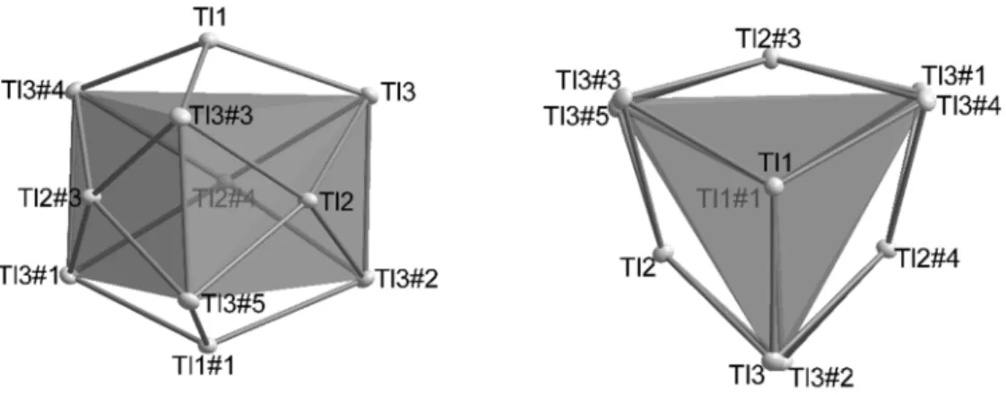
117−clusters, which are best described as a very
compressed, pentacapped trigonal prism [2]. Three symmetry independent thallium atoms are
located on three different Wyckoff positions of space group R-3c: Tl1(12c; 3-fold rotational axis), Tl2
(36f; general position) and Tl3 (18e; 2-fold rotational axis) and build up a cluster consisting of 11 Tl
atoms in point group D
3. The deviations from point group D
3hare very small (Figure 2) and are
represented by a distortion of the height of the trigonal prism built by Tl3-atoms. This distortion is
also reflected in the distances of Tl2-Tl3 (d(Tl2-Tl3): =cd) as there are two crystallographically
independent distances present. The degree of distortion decreases with increasing similarity of the
capping distances (cd). In Tables 2 and 3 the distances as well as the distortion angles are listed and
the dependence on the amount of halide incorporation is clearly evident. In contrast, the height of
the trigonal prism (Tl3-Tl3) as well as the distance of the capping atom Tl2 to the mean plane built by
Tl3 atoms [d(Tl2-plane) = 0.56 Å] and also the Tl1-Tl3 distances do not significantly change. Based on
these observations we introduce a cdd/cd
avratio (cdd: capping distance difference; cd
av: average capping distance; (1)) which allows for a quick estimation of the degree of distortion.
Table 2. Selected distances (numbering scheme according to Figure 2, values taken from [1,2]), tilt angle and cdd/cd
avvalue for K
8Tl
11and Rb
8Tl
11.
K
8Tl
11Rb
8Tl
11Tl2 Tl3 3.0476(4) 3.060 Tl2 Tl3
33.1396(4) 3.157 Tl1 Tl3
13.1304(4) 3.147 Tl3 Tl3
33.2054(7) 3.219
Tilt 4.69(2)° 4.90°
cdd/cd
av[%] 3.0 3.1
1, 3