A Framework for Dynamic Changes in Workflow Management Systems
Manfred Reichert, Peter Dadam
Abteilung Datenbanken und Informationssysteme, University of Ulm D-89069 Ulm, Germany
{reichert, dadam}@informatik.uni-ulm.de
Abstract
Current workflow management systems (WFMSs) are only applicable in a reliable and secure manner, if the business process (BP) to be supported is well- structured. As ad hoc deviations from preplanned BPs are rather the norm and form a key part of process flexibility, this limits the applicability of today's work- flow (WF) technology significantly. In this paper we present a framework for the support of ad hoc structural changes of WFs. Basic to our approach is a conceptual, graph-based WF model which has a formal foundation in its syntax and operational semantics. Based upon this model we have developed a complete and minimal set of change operations which support users in modifying the structure of WFs at runtime, while preserving their cor- rectness and consistency.
1. Introduction
WF technology offers a promising approach for the realization of process-centered application systems. A characteristic feature of "real" WFMSs (as opposed to e.g., Lotus Notes) is the separation of the application's control structures from the implementation of its task components. Maybe one of the most challenging po- tentials offered by this approach is the improved adapt- ability of application systems to changes of the BPs they support. Ideally, process-centered applications should reflect such changes without delay. This applies to the evolution of process schemes due to organizational and functional adaptations of the BP model itself [2, 3], as well as to ad hoc changes and dynamic extensions of individual BPs [1, 4, 6, 7, 9], e. g., due to unplanned events or exceptional situations [8, 10]. This paper deals with the latter type of dynamic change.
Current process-oriented WF technology is pretty good in supporting well-structured BPs, i.e., well-de- fined set of tasks, showing little variations in their pos- sible execution sequence. It does only provide rudimen- tary support with respect to dynamic structural changes
and dynamic extensions of WFs. Unfortunately, the majority of BPs is not static in the above sense. In many application domains, BPs show a high variability and dynamics in their possible task sequences [7, 9]. It is therefore not always cost-effective and possible to capture all valid task sequences in advance [10].
The applicability of WFMSs will therefore be limited, if they are too rigid or intolerant of deviations from the standard processes, set out by their designers.
A basic step towards more flexibility is the integral support of ad hoc modifications and well-aimed extensions of WFs during runtime. So a WFMS must provide functions for dynamically adding or deleting tasks resp. task blocks and for changing predefined task sequences. Dynamic changes may also concern single attributes (e.g., a deadline) of a WF object (e.g., a task).
Unrestricted changes of a WF, however, would make it difficult to have the system behave in a predict- able and reliable manner. For this reason, allowing ad hoc deviations from premodelled WFs should not mean that the responsibility for the avoidance of consistency problems (e.g., unintended lost updates) or runtime er- rors (e.g., invocation of task modules with invalid or missing input parameters) is now completely shifted to the (naive) end user. Instead, convenient rules must be defined in order to avoid an improper and uncontrolled use of change operations.
This requires that all types of structural depen- dencies between tasks are taken into consideration. As an example, consider the interdependence between the control and data flow of a WF model. Dynamic modifi- cations of premodelled task sequences are uncritical, as long as the application components (i.e., the task pro- grams) would be encapsulated and autonomous, so that they might be executed in an arbitrary order. As this is not very realistic for process-oriented application sy- stems, the data flow between the application compo- nents must be explicitly modelled. Otherwise the run- time system is unable to decide which adaptations must be made – regarding the flow of data – when the pro- cess is restructured. Furthermore, change operations must consider the state of the WF. For example, users
Copyright 1997 IEEE. Published in the Proceedings of DEXA'97, September 1-2, 1997 in Toulouse, France. Personal use of this material is permitted. However, permission to reprint/republish this material for advertising or promotional purposes or for creating new collective works for resale or redistribution to servers or lists, or to reuse any copyrighted component of this work in other works, must be obtained from the IEEE. Contact: Manager, Copyrights and Permissions / IEEE Service Center / 445 Hoes Lane / P.O. Box 1331 / Piscataway, NJ 08855-1331, USA. Telephone: + Intl. 908-562-3966.
should not be allowed to delete a task or to change its attributes, after it was completed. Finally, for security reasons it must be possible to restrict the use of change operations to selected users, to specific WF types, to specific regions of a WF graph (e.g., a single task), to certain states of a WF, or to any combination of them.
In this paper we present a conceptual and opera- tional framework for the support of ad hoc structural changes of WFs. Basic to our approach is a conceptual, graph-based WF model (ADEPT) which has a formal foundation in its syntax and operational semantics.
Based upon this model, we have developed a complete and minimal set of change operations which support users in modifying the structure of WFs at runtime, while preserving their correctness and consistency (ADEPTflex) [7]. If a change leads to the violation of correctness properties, it is either rejected or the cor- rectness of the WF graph (e.g., concerning the flow of data) must be restored by handling the exceptions (e.g., missing parameter data) resulting from the change.
This, in turn, may require concomitant changes.
Section 2 gives an overview of the ADEPT WF model. In section 3 we give some insights into the ADEPTflex model, taking the dynamic insertion of tasks into a WF graph as an example. Section 4 discusses related work and concludes with a summary, an overview of related issues not addressed within this paper and an outlook on future work.
2. Fundamentals of the ADEPT WF Model
To operationally support dynamic structural changes of a WF, a formal specification of its different aspects and of its behaviour is needed. Essential for the modelling and the execution of WFs in ADEPT is the concept of symmetrical control structures. Task sequen- ces, branchings and loop backs are specified as symme- trical blocks with well-defined start and end nodes.
These blocks may be arbitrarily nested, but are not allowed to overlap. In addition, ADEPT supports the synchronization of tasks from different execution bran- ches. The use of symmetrical control structures pro- vides the basis for the efficient analysis of the control and data flow of a WF, which has proved as crucial for the support of complex ad hoc changes. Furthermore, ADEPT defines a set of formal correctness criteria (e.g., regarding the progress of a WF or the correctness of the WF's data flow schema), that should guarantee a correct execution of WFs. The correctness properties of a WF model must be preserved in case of dynamic structural changes.
2.1 Workflow Modelling
A detailed description of the ADEPT model [cf. 7]
is beyond the scope of this paper. We only sketch some of the basic concepts, to which we refer in the following section. Simplistically, we assume that a WF schema comprises a set of tasks and control as well as data de- pendencies between them.
Flow of Control: The control flow of a WF schema is represented as a directed, structured graph (N, E).
Tasks are abstracted as a set of nodes N (of different types NT) and control dependencies between them as a set of directed edges E (of different types ET). Each WF schema has a unique start and a unique end node.
The sequential execution of tasks is modelled by linking them with control edges (ET= CONTROL_E).
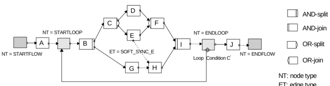
Branchings start with a split node and are synchronized symmetrically at a unique join node. ADEPT supports different types of branchings, among those are parallel processings (AND-split, AND-join), conditional rou- tings (OR-split, OR-join) and parallel branchings with final selection (AND-split / OR-join) [7]. The repeti- tive execution of a set of tasks is modelled by the use of loops. Like branchings a loop corresponds to a symme- trical block with a unique start node and a unique end node, which are connected by a loop edge (ET = LOOP_E). In addition, the end node is associated with a loop condition, which is evaluated each time the loop's end node is triggered. Finally, for the synchroni- zation of tasks from different execution branches two types of synchronization (sync) edges are supported:
• ET = SOFT_SYNC_E: A "soft" synchronization n1→ n2 is used to specifiy a delay dependency between n1 and n2, i.e., n2 may only be executed if n1 is either completed or if it cannot be triggered anymore. An example is given in Fig. 1, where H is triggered when G is completed and E is either completed or skipped (i.e., the corresponding branch is not selected for execution).
• ET = STRICT_SYNC_E: A "strict" synchroni- zation n1→ n2 requires that n1 must be successfully completed before n2 is allowed to start [cf. 7].
The use of sync edges has to meet several con- straints in order to avoid redundant control dependen- cies between tasks, cycles, or even termination prob- lems of the WF. In any case, only nodes from different branches of a parallel processing may be synchronized by the use of sync edges. Furthermore, a sync edge may not connect a node from inside a loop body B with a node not contained within B.
Flow of Data: A WF schema may be associated with a set D of global data elements (resp. variables).
Each element d ∈ D has a unique identifier idd and a domain domd. The data flow between tasks is defined by connecting their input resp. output parameters with elements from D. In this context, the input (resp.
output) data of the WF are logically treated as the output (resp. input) data of its start (resp. end) node.
Furthermore, each task n ∈ N may be associated with a set of auxiliary services (ASs), whose execution is closely connected to the task's one. An AS is either triggered when its corresponding task is started or when it is terminated, and does not appear as a separate work item in any worklist. ASs may be used, for example, to request input data for a task from the user initiating it.
In the following, we assume that for the correct execution of an action (i.e., a task resp. an AS) all input parameters must be supplied and that after its successful completion all output parameters are written. The data flow schema DF of a WF then comprises the set of all data links, connecting task resp. AS parameters with data elements from D (cf. Fig. 2.). ADEPT imposes a set of restrictions which govern the nature of a correct data flow schema. For each data link df ∈ DF we re- quire that the domains of the data element ddf and the parameter pardf it connects are type compatible. In addi- tion, each input resp. output parameter of an action must appear in exactly one data link df ∈ DF. To avoid the invocation of application components with missing input data, we further require that before a specific action may be executed, its input parameters must be supplied; i.e., all data elements to which the action's in- put parameters are connected must be written at least once within all valid task sequences leading to the exe- cution of that action. Trivially, for a given task which reads a data element d, this rule is satisfied when d is written by the start node of the WF or by a preceding AS. Note, that this rule also guarantees that the input parameters of the end node, i.e., the output parameters of the WF, are supplied. Finally, in order to avoid unin-
tended lost updates we do not allow tasks from different branches of a parallel processing (with AND-join) to have write access to the same data element, unless they are synchronized by a sync edge.
Due to lack of space, we omit the presentation of algorithms for analysing a data flow schema with re- spect to these rules. For a basic understanding an ex- ample is more suitable. In the WF graph depicted in Fig. 2 the task G may read the data elements d1 and d2, but is not allowed to access d3 as this data element is not written within all valid action sets leading to the execution of G – valid action sets are {STARTFLOW, A, B, D, F} and {STARTFLOW, A, B, F}. The task H, however, may read the data elements d1, d2 and d3 as each of them is written within all task sets leading to the execution of H. Furthermore, G is not allowed to write d3 as d3 might be concurrently written by task C.
The presented rules constitute the basis for detect- ing exceptions resulting from a dynamic structural change and for adjusting the data flow schema when the WF is restructured. Note, that changes of a WF may violate the presented rules if no further precautions are made. The deletion of a task, for instance, is accompa- nied by the deletion of the data links connecting its out- put parameters with elements from D. This, in turn, may lead to missing parameter data for succeeding tasks and therefore to an invalid data flow schema. On the other hand, the dynamic insertion of a task and the
NT = STARTFLOW NT = ENDFLOW
NT: node type ET: edge type
Loop Condition C* ET = SOFT_SYNC_E
B C
G E
H F
I D
A
NT = STARTLOOP NT = ENDLOOP
ET = LOOP_E
J
AND-split AND-join OR-split OR-join
Figure 1. Example of a simple WF model.
data elements
data-link
ET = SOFT_SYNC_E B
F D
G E
H C
NT = STARTFLOW NT = ENDFLOW
d1 d2 d3
Figure 2. Example of a data flow schema.
addition of data links connecting its output parameters with elements from D may lead to lost updates.
2.2 Workflow Execution
Whether a dynamic change may be applied to a WF instance or not depends on the state of the WF, too. A WF's state is defined by the current state of the nodes and edges of the WF graph, the values of its data ele- ments (possibly stored in different versions) and infor- mation about its previous execution history. The state of a task n is described by the current state NSn of its node – NOT_ACTIVATED, ACTIVATED, RUNNING, COMPLETED or SKIPPED – and the total number Itn of its previous executions. Finally, the state ESe of an edge e of a WF graph is either NOT_SIGNALED, FALSE_SIGNALED or TRUE_SIGNALED.
Each time an edge (of arbitrary type) is signalled, the state of its destination node is re-evaluated accor- ding to the execution rules defined by ADEPT. These rules define the conditions under which a node may be activated (i.e., routed to worklists). A node representing an AND-join, for instance, is activated, if it is in the state NOT_ACTIVATED and all ingoing control edges are in the state TRUE_SIGNALED. Furthermore all strict sync edges must be signalled as true and all soft sync edges as either true or false. On the other hand, a node is skipped if at least one of its ingoing control edges is signalled as false. Comparable execution rules are defined for all node types of a WF (incl. the start / end nodes of loops).
The completion of a node, in turn, leads to the si- gnalling of its outgoing edges. Upon successful comple- tion of an AND-split node, for example, its outgoing control and sync edges are signalled as true, which may lead to the activation of succeeding tasks, and so on. On the other hand, if a task is skipped (e.g., when its corresponding branch is not selected for execution) all outgoing edges are signalled as false, which may lead to the skipping of succeeding tasks. In summary, the marking of edges follows well-defined signalling rules, which are based on the operational semantics of the ADEPT model. We omit further details and refer the interested reader to [7].
As we will see in the following section, execution and signalling rules play an important role in connec- tion with the reevaluation of the state of a WF graph after structural changes have been applied to it.
3. Supporting Dynamic Changes of WFs
Based upon the ADEPT model we have developed a complete and minimal set of operations which serve
as the framework for dynamic structural changes of WFs (ADEPTflex). The main emphasis in designing these operations was put on consistency and correctness is- sues. The application of a change operation to a specific WF must result in a WF with a syntactically correct schema and with a "legal" state, i.e., the change should not cause inconsistencies and runtime errors. Further- more each operation should be applicable to any WF in- stance with arbitrarily structured schemes. Finally, the provided change operations should be complete and minimal in the sense of being able to realize each possible form of restructuring of a WF graph.
In summary, ADEPTflex comprises operations for in- serting and deleting tasks (resp. task blocks) into resp.
from a WF graph, for fast forwarding the progress of a WF by skipping the execution of tasks (with our with- out finishing them later), for jumping to currently inac- tive parts of a WF graph, for serializing tasks that were previously allowed to run in parallel (and vice versa) and for the dynamic iteration resp. rollback of a WF region (incl. the undoing of temporary structural chan- ges). Based upon these operations higher-level services such as the replacement of a specific WF region by a new one can be implemented. The insert operation shall serve as an illustrative example and will be discussed in more detail. For an overview of the other change opera- tions the interested reader is refered to [7].
3.1 Dynamic Insertion Of Tasks
When a new task is inserted into a WF graph, new nodes and edges (incl. data links) must be added, while preserving the correctness and consistency of the WF.
Current WFMSs do not provide a sufficient level of fle- xibility and consistency with respect to this operation.
Typically they only allow the addition of an activity upon completion of a task and before the activation of its successors [e.g., 5, 6]. Important aspects, e.g., con- cerning data integrity, are left aside. To be broadly ap- plicable, an insert operation must be complete in the sense of being able to realize each possible form of insertion. Generally, it must be possible to add new tasks to a WF at any point of time during its execution, to work on an inserted task concurrently to other tasks, to synchronize the execution of an inserted task with those of other tasks, to insert tasks into WF regions that have not yet been entered, to dynamically map the para- meters of the inserted task to existing or to newly ge- nerated data elements, and so on.
In the ADEPTflex model, a new task X – together with associated auxiliary services SX, data elements DX and data links DFX – may be inserted into a WF graph by synchronizing its execution with two node sets Mbefore
and Mafter. The execution semantics of X is then as fol- lows: X is activated as soon as all tasks from Mbefore are either completed or cannot be triggered anymore, i.e., the tasks defined by Mbefore delay the execution of X. On the other hand, tasks from Mafter may only be activated after X has been completed. This generic approach allows us to synchronize X with tasks from different execution branches.
Preconditions: To ensure that the application of the insert operation leads a WF graph with a syntactically correct schema and with a legal state, the following constraints must be satisfied: (P1) Firstly, for all na∈ Mbefore , nb ∈ Mafter the node na must precede nb in the flow of control. (P2) Secondly, to avoid unnecessary synchronizations, nodes from Mbefore (resp. Mafter) should not succeed each other in the flow of control. (P3) Finally, the region covered by the nodes between Mbefore and Mafter may only contain complete loop control structures. Besides structural constraints, the applicabi- lity of the insert operation may depend on the state of the WF graph, too. We require that all nodes from Mafter must be in one of the states NOT_ACTIVATED or ACTIVATED, i.e., the insertion of a new task X as a predecessor of an already running or terminated task is disallowed. If X is inserted as a predecessor of an acti- vated task, i.e., the task has already been routed to worklists, the insertion may only take place after the corresponding work items have been removed. The nodes from Mbefore may be in an arbitrary state.
Insert Algorithm: First of all, we concentrate on the restructuring of the control flow graph (N, E). If
Mbefore and Mafter satisfy the above constraints, a task X is
added to the graph by applying the following steps:
1. Find the minimal, closed subgraph B ⊆ (N,E) that contains all nodes from Mbefore∪ Mafter (excl. the start/
end node of the WF graph). Let nbegin denote the start node and let nend denote the end node of B.
2. Insert an AND-split n1 preceding the node nbegin and a corresponding AND-join n2 succeeding nend – Both, n1 as well as n2 are supposed to be null tasks (i.e., tasks without associated actions); n1 / n2 takes over the input / output firing behaviour and the ingoing /outgoing control edges of nbegin / nend
3. Insert X as a new branch between n1 and n2 and synchronize it with the tasks from Mbefore and Mafter, i.e., for each B ∈ Mbefore (excl. the start node of the WF graph) add a sync edge B®X and for each
A ∈ Mafter (excl. the end node of the WF graph) add a
sync edge X®A (with ET = SOFT_SYNC_E) We omit further details and present two examples instead. The first one is depicted in Fig. 3 and shows how a task X is inserted between two sets of nodes. The example shows that nodes and edges might be added to the WF graph, that are not necessarily required to achieve the desired execution semantics. Such unneces- sary graph elements may be removed from the resulting WF graph by applying a set of well-defined reduction rules [cf. 7]. The effect of these rules to the WF graph
1. Find the minimal block, containing C, D and F
A
X
B C
D
F
E G
Insert task X between {C, D} and {F}
⇒ Mbefore = {C, D}, Mafter = {F}
3. Apply reduction rules
2. Insert n1 and n2 before resp. after the block. Insert X between n1 and n2 and synchronize it with C, D and F.
a)
b) A B
C
D
F
E G
nbegin nend
c)
X
A B
C
D
F
E G
n1 nbegin nend n2
d)
X
B C
D
F
E G
A
ET=SOFT_SYNC_E
NT= EMPTY
Figure 3. Insertion of a new task between two sets of nodes.
from Fig. 3c) is shown in Fig. 3d). A second example is given in Fig. 4 where a new task is inserted between an AND-split and its corresponding AND-join.
On the whole, the insert operation substitutes a block B of the WF graph by a symmetrical block, namely a parallel branching with the inserted task X and B as its branches. The symmetrical structuring is therefore preserved and the insertion of the null tasks does not influence the termination behaviour of the WF.
The restrictions for the use of sync edges (cf. section 2.1) are further satisfied as the added edges do only synchronize tasks from different branches of a parallel branching – namely the task X with tasks from B –, do not link a node contained within a loop body with X (cf. P3) and do not lead to cycles resp. termination problems. The latter is guaranteed by the ordering of the tasks from the sets Mbefore and Mafter (cf. P1).
State Reevaluation: After a task has been added to a WF graph, the state of its nodes and edges (incl. the newly inserted ones) must be re-evaluated. This reeval- uation is based on the execution and signalling rules de- fined by the ADEPT model (cf. section 2.2). Whether the newly inserted task is activated immediately or not depends on the current state of the WF graph. The for- mer is the case, if at insertion time all nodes from Mbefore are in a finite state. As a simple example consider the WF graph shown in Fig. 4b), whose reevaluation yields to the graph depicted in Fig. 4c). Note, that the addition of a new task does not necessarily mean that it will be activated at all. If a task is inserted into the region of a WF graph that has not yet been entered, its execution may depend on future routing decisions.
Adjusting the Flow of Data: A task X may be
"plugged" into a WF graph, together with associated data elements DX, auxiliary services SX and data links DFX. It must be ensured that the resulting data flow schema meets the correctness properties defined in sec- tion 2.1. A simple approach to guarantee the supply of X's input parameters, for instance, would be to request them from the user initiating X, e.g., by assigning a pre- ceding AS to X whose output parameters correspond to X's input parameters [cf. 7]. In practice, this simple ap- proach would not always yield to a satisfactory solu- tion, since redundant data entries may result in the course of a WF, potentially leading to data inconsisten- cies. For a more intelligent support it must also be pos- sible to dynamically map the parameters of the inserted task to already existing data elements from D. This rai- ses a variety of challenging issues with respect to dyna- mic parameter mapping, which can only be sketched here. First of all, the data elements CX⊆ D to which X's input parameters may potentially be mapped is CX = {d ∈ D | ∀ V ∈ VX: ∃ n* ∈ V: n* writes into d)}, where VX denotes the set of all valid task sets, leading to the execution of X. A specific input parameter of X may only be linked to a data element d ∈ CX if their domains correspond to each other. Of course, this purely syntactical approach would be insufficient in practice and would leave significant complexity to the user. A more sophisticated approach, which aims at the semi-automatic mapping of parameters to data elements, is sketched in [7]. Basic to this approach is a controlled vocabulary which is used for the naming of data elements and task parameters. Finally, the set CX may be extended by considering the state of the WF,
1. Find the minimal block containing D and G
2. Insert n1 and n2 before rsp. after the block. Insert X as a new branch between n1 and n2 and synchronize it with D and G.
3. Apply reduction rules and re-evaluate the state of the nodes and edges
ES = TRUE_SIGNALED ES = FALSE_SIGNALED Insert task X between D and G:
⇒ Mbefore = {D}, Mafter = {G}
ü ü
C B A
ü D
F E
G ü
✖ H
a)
F E ü ü
D G H
X D
c)
b) ü
D F E
G ü
H X
n1 nbegin nend n2
X
NS = ACTIVATED NS = COMPLETED ü
NS = SKIPPED
✖
NS = RUNNING
Figure 4. Adding a new task X between the AND-split D and the AND-join G.
too. As an example, take the insertion shown in Fig. 4 and assume that B is the only task that writes a specific data element d ∈ D. Since B is completed at the time X is added, X may read the value of d, although it is not contained within CX. Following this approach, it might become necessary to undo the insertion of X in case of a backward operation [cf. 7].
Similar reflections must be made regarding link- ages of the output parameters of inserted tasks to exis- ting resp. newly inserted data elements (cf. section 2.1)
3.2 Further Issues
With increasing complexity and expressive power of the used WF meta model, it becomes more and more difficult to handle dynamic changes of WFs – together with the resulting exceptions – in a proper and secure manner. As an example, consider the use of loops.
When a loop enters a new iteration, the control of the WF is passed back to a previous point of the flow. For ad hoc changes, this means that whenever they affect a loop's body, it must be clear whether the change should only be valid for the current iteration (temporary change) or for following iterations, too. In the former case, the change must be undone before the loop may enter its next iteration [cf. 7].
For security reasons, ADEPTflex allows WF de- signers to restrict the use of a change operation to speci- fic users, WF types, regions of a WF graph, states of a WF, or to any combination of them. Basic to this is a powerful meta model for capturing organizational enti- ties and relationships between them. Finally, for the implementation of flexible client applications a set of API calls is offered to programmers. This API also provides functions for querying information about the context in which the change takes place.
4. Summary and Outlook
Several approaches exist which aim at the support of dynamic changes of WFs at runtime. The proposals made by ProMInanD [6], ObjectFlow [5], MOBILE [4], and many others [e.g., 1, 9] are worth mentioning. In summary, current proposals are rather based on "ad hoc" WF models, which lack a clear theoretical basis.
This, in turn, makes it difficult for the runtime system to handle ad hoc changes in a proper and secure man- ner. There are only few approaches which address cor- rectness issues in connection with dynamic structural changes. Notable exceptions are presented in [2, 3]. In contrast to ad hoc changes applied to individual WF in- stances, these approaches deal with schema changes and their propagation to WFs whose execution started with
the old schema. As ADEPTflex both approaches are based on a conceptual WF model. However they restrict their considerations to dynamic changes of the control flow while other relevant aspects are left aside.
Our paper has illustrated that the dynamic change problem has many facets. We have introduced basic concepts of the ADEPT WF model, which offers a good compromise for the trade-off between the expressive power of a WF model and the complexity of its algorithms for model checking. We believe that this is crucial for the efficient support of complex dynamic structural changes. The ADEPTflex model which is based upon ADEPT has been presented and its adequacy with respect to dynamic changes has been demonstrated.
Taking the dynamic addition of tasks as an example, we have shown that the correctness properties of ADEPT and the preconditions defined for each type of change operation constitute a good basis for this.
Besides the issues addressed in this paper, there are numerous areas that warrant further attention. The sup- port of simultaneous changes, the interplay of dynamic changes at the schema level with ad hoc changes at the instance level and the provision of "intelligent" user interfaces name just a few examples.
References
[1] P. Barthelmess, J. Wainer: Workflow Systems: a few Definitions and a few Suggestions. Proc Conf on Organizational Comp Sys, 1995, pp. 138 - 147.
[2] F. Casati, S. Ceri, B. Pernici, G. Pozzi: Workflow Evolu- tion. Proc 15th Int'l Conf on Conceptual Modelling, Cottbus, Germany, 1996, pp. 438-455
[3] C. A. Ellis, K. Keddara, G. Rozenberg: Dynamic Change Within Workflow Systems. Proc Conf on Organizational Comp Sys, 1995, pp. 10 - 21
[4] P. Heinl, H. Schuster, K. Stein: Behandlung von Ad-hoc- Workflows im MOBILE Workflow-Modell. Proc Softwaretechnik in Automation und Kommunikation, Munich, 1996, pp. 229 - 242.
[5] M. Hsu, C. Kleissner: ObjectFlow: Towards a Process Management Infrastructure. Distributed and Parallel Databases, Vol. 4, 1996, pp. 169-194
[6] B. Karbe et al.: Support of Cooperative Work by Electronic Circulation Folders, SIGOIS Bulletin, Vol.
11, No. 2,3, 1990, pp. 109-117
[7] M. Reichert, P. Dadam: ADEPT – Supporting Dynamic Changes of Workflows Without Loosing Control.
Technical Report No. 97–07, University of Ulm, 1997.
[8] H. Saastamoinen: On the Handling of Exceptions in Information Systems. Ph.D. Thesis, University of Jyvaskyla, Finland, 1995.
[9] R. Siebert: Adaptive Workflow for the German Public Administration. Proc 1st Int'l Conf on Practical Aspects of Knowledge Management, Basel, Switzerland, 1996.
[10] D. M. Strong, S. M. Miller: Exceptions and Exception Handling in Computerized Information Processes. ACM Trans on Inf Sys, Vol. 13, No. 2, 1995, pp. 206 - 233.