CO
2-microemulsions with additives:
Phase behaviour, microstructure and pressure-induced kinetics
Inaugural-Dissertation zur
Erlangung des Doktorgrades
der Mathematisch-Naturwissenschaftlichen Fakultät der Universität zu Köln
vorgelegt von
Yvonne Pütz
aus Bad Soden
Köln, Februar 2015
Berichterstatter: Prof. Dr. Reinhard Strey Prof. Dr. Annette M. Schmidt
Tag der mündlichen Prüfung: 10. April 2015
Meiner wunderbaren Familie
„There are times in life when people must know when not to let go.
Balloons are designed to teach small children this.“
- Terry Pratchett
ABSTRACT
Improved building insulation is an important part of today´s efforts on energy saving. Here, nano- insulation materials promise especially low thermal conductivity. Therefore, an easy and cost-efficient production of these materials is an aim of present material research. One approach towards these materials is the expansion and fixation of polymerisable microemulsions of supercritical blowing agents. However, the nano-sized bubbles are found to undergo undesired coarsening processes. In order to reduce the increasing interfacial tension emerging during expansion and therewith the coarsening it was suggested to add low-molecular hydrophobic substances to the supercritical microemulsion. And indeed, the addition of cyclohexane to a microemulsion of the type brine – CO2 – fluorinated surfactants was found to reduce the fluorinated surfactant content – a measure for the interfacial tension - considerably. In this work a systematic small-angle neutron scattering (SANS) contrast variation was performed and the data were analysed by model-independent Fourier analysis. It was found that a concentration gradient of cyclohexane inside the CO2/cyclohexane microemulsion droplets forms. Interestingly, the analysis reveals a depletion zone close to the amphiphilic film which presumably develops due to the known repulsive interactions of cyclohexane and the fluorinated surfactant tails. Using a specially designed high pressure SANS cell to perform stroboscopic pressure jumps, the influence of cyclohexane on pressure-induced elongation of microemulsion droplets as well as the early state of foaming after expansion was studied. Here, the pressure-dependent thermodynamic stability of such microemulsions allows for a fast repeatability of the pressure cycles.
It turned out that cyclohexane systematically slows down the structural changes in all processes.
Parallel pressure jump experiments with poly-(N-isopropylacrylamide) (PNIPAM) particles revealed that hydration and dehydration kinetics can be studied with the same experimental setup. The first kinetic experiments which combine a CO2-microemulsion mixed with PNIPAM particles indicate that PNIPAM acts as a stabiliser for the microemulsion and further reduces the thermodynamic driving force of the demixing process.
Die Gebäudeisolation stellt einen wichtigen Teil der Bemühungen zur Energieeinsparung dar, wobei nano-Isolationsmaterialien besonders niedrige Wärmeleitfähigkeiten versprechen. Eine einfache und kosteneffiziente Produktion solcher Materialien steht daher im Fokus aktueller Forschung. Eine Möglichkeit zur Herstellung solcher Materialien besteht aus Expansion und Fixierung einer polymerisierbaren Mikroemulsion mit überkritischem Treibmittel, wobei bei der Expansion allerdings durch Zunahme der Grenzflächenspannung Vergröberungsprozesse der nano-skaligen Tröpfchen auftreten können. Ein Ansatz, diese Alterung zu verringern, besteht aus dem Zusatz niedermolekularer hydrophober Substanzen zu der überkritischen Mikroemulsion. Durch Zugabe von Cyclohexan zu einer Mikroemulsion des Types Salzlösung – CO2 – fluorierte Tenside konnte eine deutliche Reduzierung des Tensidgehaltes – ein Maß für die Grenzflächenspannung – erzielt werden. In dieser Arbeit wurde eine systematische Kontrastvariation mit Kleinwinkelneutronenstreuung (SANS) durchgeführt, wobei die Daten mit einer modelunabhängigen Fourier-Analyse ausgewertet wurden. Es stellte sich heraus, dass ein Konzentrationsgradient an Cyclohexan innerhalb der mit CO2 und Cyclohexan gefüllten Mizellen gebildet wird. Dies macht deutlich, dass es zu einer Verarmung an Cyclohexan in der Nähe des amphiphilen Films kommt, welche auf die bekannten repulsiven Wechselwirkungen zwischen Cyclohexan und den fluorierten Tensidschwänzen zurückzuführen ist.
Unter Verwendung einer speziell entwickelten Hochdruck-SANS-Zelle wurde bei stroboskopischen Drucksprüngen beobachtet, dass Cyclohexan die Kinetik von druckinduzierten Elongationen und die frühen Stadien des Schäumprozesses deutlich verlangsamt. Parallel dazu durchgeführte Drucksprungexperimente mit poly-(N-isopropylacrylamid) (PNIPAM) Partikeln zeigten, dass die Hydratations- und Dehydratationskinetiken ebenfalls mit diesem experimentellem Aufbau untersucht werden konnten. Erste kinetische Experimente, welche CO2-Mikroemulsionen mit PNIPAM Partikeln kombinieren, deuten an, dass PNIPAM als Stabilisator für die Mikroemulsion fungiert und die thermodynamische Triebkraft zur Entmischung weiter reduziert.
DANKSAGUNG
Die vorliegende Arbeit wurde im Zeitraum Juni 2012 bis Februar 2015 am Institut für Physikalische Chemie der Universität zu Köln unter der wissenschaftlichen Anleitung von Herrn Prof. Dr. Reinhard Strey angefertigt. Ihnen, Herr Strey, möchte ich für die Möglichkeit danken, diese Arbeit in Ihrer Arbeitsgruppe anzufertigen, dass Sie mich immer unterstützt haben und mit Ihrer steten Diskussionsbereitschaft viele wertvolle Anstöße für diese Arbeit geliefert haben. Einen besonderen Dank möchte ich dafür aussprechen, dass Sie mir stets großes Vertrauen entgegen gebracht haben und ich auch eine Vielzahl von eigenen Ideen verfolgen durfte, die nicht von Anfang an geplant waren.
Darüber hinaus bin ich Ihnen sehr dankbar, dass Sie mir immer wieder die Gelegenheit gegeben haben, internationale Erfahrungen zu sammeln – sei es durch Messreisen nach Grenoble, durch den Besuch internationaler, wissenschaftlicher Tagungen oder durch den Forschungsaufenthalt in London.
Frau Prof. Dr. Annette M. Schmidt möchte ich für die Übernahme des Korreferats dieser Arbeit danken. Auch für Ihre Unterstützung für mögliche zukünftige Projekte bin ich Ihnen sehr dankbar.
Ihre Vorlesung und die Diskussionen im Rahmen einer Bachelorarbeit haben einige wichtige Denkanstöße besonders für den PNIPAM Teil geliefert!
Ein ganz besonderer Dank geht an Herrn PD Dr. Thomas Sottmann. Du hast mich von Beginn an unterstützt und in die Neutronenstreumessungen einbezogen, wofür ich Dir sehr dankbar bin. Deine stete Bereitschaft, meine zahlreichen Fragen zu beantworten, die vielen wissenschaftlichen Diskussionen über meine Daten und die viele Zeit, die Du in Proposals, Paper, verschiedene Anträge und nicht zuletzt in die Durchsicht meiner Arbeit gesteckt hast, haben entscheidend dazu beigetragen, dass diese Arbeit so möglich war. Die vielen Schichten, die wir zusammen in Grenoble verbracht haben, werden mir mit Sicherheit in Zukunft fehlen!
Für stets exzellente und erfolgreiche Zusammenarbeit möchte ich mich bei allen Mitarbeitern der Feinmechanischen Werkstatt, besonders aber bei Herrn Herbert Metzner bedanken. Ohne Ihre vielen Ideen und Ihren Glaube an das Projekt wäre die Weiterentwicklung der SANS-Zelle nicht möglich gewesen. Darüber hinaus möchte ich mich bei Herrn Viktor Clippert bedanken, für das Engagement und die vielen interessanten technischen Diskussionen. Außerdem gilt mein Dank Herrn Thomas Michaelis, für die vielen Stunden, die Sie an der Zelle herumgeschraubt haben. Und vielen Dank dafür, dass Sie immer so große Geduld aufgebracht haben, mir die technischen Zeichnungen und das Innenleben einiger Geräte und Bauteile zu erklären. Darüber hinaus möchte ich mich bei Frau Leyla Balici für die Anfertigung der technischen Zeichnungen bedanken.
Für die stets gute Zusammenarbeit während der Neutronenstreumessungen möchte ich mich bei den Local Contacts des D22, Herrn Dr. Albrecht Wiedenmann und Herrn Dr. Lionel Porcar, bedanken.
Diskussionen zur Verfügung gestanden habt! Auch den Local Contacts vom D11, Herrn Dr. Ralf Schweins und Herrn Dr. Peter Lindner, möchte ich herzlich für die Zusammenarbeit danken.
Besonders Dir, Ralf, außerdem ein herzlicher Dank für die Unterstützung des geplanten Projekts.
Dabei möchte ich auch Herrn Kenneth Honniball (D22) und Herrn David Bowyer (D11), Techniker am ILL, nicht vergessen. Vielen Dank für die Besorgung der Vielzahl an Gasflaschen und die Spezialanfertigungen während der Messzeit!
Ebenfalls im Zusammenhang mit Neutronenstreumessungen möchte ich mich bei den Mitgliedern der SANS Teams bedanken. Besonders die TISANE Messzeiten mit Herrn Dr. Nils Becker, Frau Lena Grassberger, Herrn Dr. Alexander Müller, Herrn Dr. Roland Oberhoffer und Herrn PD Dr. Thomas Sottmann waren immer ein ganz besonderes Erlebnis! Mit exzellenter Teamarbeit haben wir alle zusammen so manch scheinbar unlösbares Problem gelöst! Von den vielen Dichtungen, die wir zusammen gewechselt haben, Thomas, werde ich bestimmt eine als Erinnerung aufheben. Vielen Dank für die tatkräftige Unterstützung, die hervorragende Zusammenarbeit und die zwar anstrengenden, aber auch oft sehr lustigen Nachtschichten, in denen besonders Du, Lena, mich mit einem geklatschtem „Hopp, hopp!“ öfter wieder auf Trab gebracht hast! Ganz besonders bedanken möchte ich mich an dieser Stelle bei Dir, Alex, dafür, dass Du mir Neutronenstreuung und TISANE mit großer Geduld erklärt hast. Auch die Messzeiten mit Frau Carola Harbauer, Herrn Dr. Helge Klemmer, Herrn Stefan Lülsdorf, Frau Ji-Yoon Yang und Frau Diana Zauser waren sehr lehrreich für mich und auch an euch vielen Dank für die gute Zusammenarbeit und die vielen interessanten Diskussionen! Für die Unterstützung im Zusammenhang mit dem GIFT Verfahren möchte ich mich darüber hinaus herzlich bei Herrn Prof. Dr. Otto Glatter und bei Herrn Dr. Michael Klostermann bedanken.
Einen kurzen aber besonderen Teil meiner Doktorarbeit habe ich in der „Polymer and Microfluidics group“ von Dr João T. Cabral am Imperial College in London verbracht. João, ich möchte Dir noch einmal ganz herzlich danken, dass ich, wenn auch nur für ein paar Wochen, Mitglied Deiner Gruppe werden durfte, und auch für die vielen interessanten Diskussionen über die gesammelten Daten. In dieser Zeit habe ich nicht nur viel gelernt, sondern auch viele neue Freunde gewonnen! Den Mitgliedern dieser Gruppe, ganz besonders aber Herrn Carlos Garcia-Lopez und Herrn Dr. Andreas Stavros Poulos, möchte ich einen herzlichen Dank aussprechen für die Unterstützung bei den SLS Messungen und des Microfluidic-Projektes! An dieser Stelle ist ein Dankeschön an den Fonds der Chemischen Industrie passend für die finanzielle Unterstützung, die diesen Forschungsaufenthalt ermöglicht hat.
Für die sorgfältige Durchsicht dieser Arbeit möchte ich mich zudem bei Frau Lena Grassberger, Frau Carola Harbauer, Herrn Dr. Helge Klemmer (besonders bei Dir), Herrn Dr. Alexander Müller, Herrn
Dr. Thomas Sottmann und Herrn Dr. Andreas Stavros Poulos ganz herzlich bedanken! Bei Herrn Dr.
Lhoussaine Belkoura bedanke ich mich für die Unterstützung beim Aufbau der HPDLS Anlage. Ohne Sie, Herr Belkoura, wäre dieses Projekt so nicht möglich gewesen!
Natürlich gebührt auch den Mitgliedern des Arbeitskreises ein großer Dank für die stets angenehme, konstruktive Arbeitsatmosphäre und die ständige Diskussionsbereitschaft. Dabei besonders hervorheben möchte ich meine Laborkollegen Frau Lena Grassberger, Frau Melissa Hermes, Herrn Dr. Alexander Müller, Herrn Dr. Roland Oberhoffer und Frau Kavita Singh-Ghotra. Besonders, wenn es um SANS Ergebnisse ging, warst auch Du, Helge, immer für Diskussionen zu haben. Für die vielen Phasendiagramme und DLS-Messungen möchte ich mich außerdem sehr herzlich bei Frau Melissa Hermes bedanken. Gerade in Zeiten vor Grenoble weiß ich nicht, wie ich die Vorbereitung ohne Dich geschafft hätte! Auch bei Frau Vanessa Rauch möchte ich mich bedanken, für Dein Engagement während Deiner Bachelorarbeit, deren Ergebnisse auch in meine Doktorarbeit beeinflusst haben. Den Herren Dr. Jan-Hubert Wittmann und Tim Schreiner bin ich für sehr kompetente Hilfe bei allen IT- Problemen sehr dankbar!
Zusätzlich zu all jenen namentlich nicht genannten Freunden und Bekannten in der Chemie der Uni Köln möchte ich mich natürlich auch bei meinen Freunden außerhalb der Universität bedanken, die stets für ein gutes Gleichgewicht zwischen Arbeit und Freizeit gesorgt haben. Nicht nur meine Freunde, sondern natürlich auch meine großartige Familie ist mir immer eine verlässliche Stütze.
Dabei besonders bedanken möchte ich mich vor allem bei meinen vier Großeltern, die mich bereits mein ganzes Leben lang unterstützt haben und ausnahmslos und immer für mich da waren und sind.
Ich bin sehr stolz, solche Großeltern wie Euch zu haben! Auch meinen Eltern, Frau Susanne Pütz- Hebel und Herrn Peter Pütz möchte ich danken. Wann immer ich Dich besucht habe, Mama, habe ich bestimmt ein Kilo zugenommen und noch genug Essen für eine Woche mit nach Köln zurück genommen! Bei Dir, Papa, möchte ich mich neben der allgegenwärtigen Unterstützung vor allem für die Radtouren im Kölner Umland bedanken, die meine Ortskenntnisse erheblich verbessert haben!
Ein ganz besonderer Dank geht an Herrn Stefan Reimann. Du weißt selbst am besten, wie wichtig Deine Unterstützung nicht nur in den stressigen Zeiten vor Grenoble und vor der Abgabe für mich war. Ich bin sehr froh, Dich an meiner Seite zu haben!
1 Introduction ... 1
2 Fundamentals ... 7
2.1 Microemulsions ... 7
2.1.1 Phase behaviour of binary mixtures ... 7
2.1.2 The phase prism – ternary mixtures ... 8
2.1.3 Curvature of the amphiphilic film and microstructure ... 12
2.2 Microemulsions with supercritical carbon dioxide ... 16
2.2.1 Flourinated surfactants and their impact on CO2-microemulsions ... 16
2.2.2 CO2-microemulsions as templates for nanoporous foams ... 17
2.2.3 Aging phenomena and the concept of anti-ageing agents ... 19
2.3 Thermoresponsive polymers ... 23
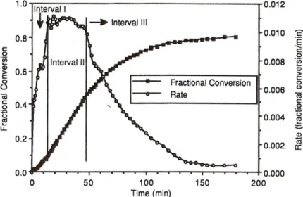
2.3.1 Emulsion polymerisation ... 23
2.3.2 Swelling of poly-(N-isopropyl)acrylamide ... 27
2.3.3 Microgel applications ... 29
2.4 Neutron scattering ... 31
2.4.1 Small angle neutron scattering ... 32
2.4.2 Neutron contrast variation ... 34
2.4.3 Raw data treatment and data recording for static measurements ... 36
2.4.4 Data analysis: Description of scattering curves ... 38
2.4.5 The stroboscopic high pressure SANS cell ... 51
2.4.6 Data recording for kinetic measurements ... 55
2.4.7 Time Involved Small Angle Neutron Scattering Experiments (TISANE) ... 58
2.5 Light scattering ... 64
2.5.1 Dynamic light scattering ... 65
2.5.2 Dynamic light scattering under high pressure ... 68
2.5.3 Static Light Scattering ... 69
3 Cyclohexane as hydrophobic additive to supercritical fluorinated microemulsions ... 70
3.1 Microstructure of CO2/cyclohexane-microemulsions with flourinated surfactants ... 70
3.1.1 Phase behaviour ... 70
3.1.2 Systematic SANS contrast variation ... 72
3.1.3 Data evaluation I: Model-dependent analytical fitting functions ... 76
3.1.4 Data evaluation II: Model-independent Fourier transformation ... 78
3.1.5 Measurements at elevated temperature and wB ... 85
3.1.6 Conclusion ... 87
3.2 Kinetics of structural changes of CO2-microemulsions... 89
3.2.1 Phase behaviour and microstructure ... 89
3.2.2 Pressure jumps within the thermodynamically stable state ... 98
3.2.3 Influence of cyclohexane on changes of microstructure ... 107
3.2.4 Pressure jumps to thermodynamically unstable states... 109
3.2.5 Influence of cyclohexane on kinetics of demixing processes ... 113
3.3 The TISANE option ... 117
3.3.1 TISANE experiments: State of the art ... 117
3.3.2 Improvements of the SHP-SANS cell ... 117
3.3.3 Applying the TISANE option to microemulsions ... 120
3.4 Conclusion ... 124
4 Influence of hydrostatic pressure on PNIPAM particles ... 127
4.1 PNIPAM particles at elevated hydrostatic pressure ... 127
4.1.1 Dynamic light scattering ... 128
4.1.2 Small Angle Neutron Scattering ... 132
4.1.3 Static light scattering ... 138
4.2 Swelling and deswelling kinetics induced by sudden pressure jumps ... 142
4.3 Microfluidics ... 149
4.3.1 Newly developed microfluidic setup for temperature jumps ... 149
4.3.2 Results of temperature jump experiments ... 150
4.3.3 Discussion ... 153
4.4 Conclusion ... 154
5 Microemulsions and PNIPAM under mutual confinement ... 155
5.1 Phase behaviour ... 155
5.2 Light and neutron scattering ... 157
5.3 First kinetic experiment with microemulsions and PNIPAM ... 161
5.4 Conclusion ... 161
6 Summary ... 163
7 Appendix ... 167
7.1 Abbreviations and Symbols ... 167
7.2 Experimental methods ... 172
7.2.1 Determination of the Phase Boundaries of Microemulsions ... 172
7.2.2 Neutron Scattering ... 174
7.2.3 Light Scattering ... 176
7.2.4 Emulsion polymerisation ... 177
7.2.5 Microfluidics ... 178
7.3 Chemicals and Substances ... 179
7.4 Tables ... 179
8 Bibliography ... 183
1
1 Introduction
Polymer foams are an aspect of modern life. Disposable packaging of fast food, building insulation, cushioning of furniture, running shoes and bicycle helmets are a few examples [1]. The properties of the foams differ considerably with the polymer and its processing. While polystyrene (PS) is a common example for insulation applications, polymethylmethacrylate (PMMA) is often used in automotive industry and civil engineering because of its exceptional resistance to weathering [2].
In recent years the prospect of foams with a pore size in the submicron range has achieved increasing attention. These materials exhibit a high application and market potential due to a high-performance thermal insulation capacity which can be improved by a factor of at least 3 if the pores are smaller than 100 nm [3]. A high sound absorption, optical transparency and a uniquely high stability against applied forces are further benefits [4, 5]. The reasons for these improved features are based on the nanostructure. Optical transparency is achieved because light scattering is negligible if the pore size is much smaller than the wavelength of visible light. The Knudsen effect predicts that heat transfer over the cell gas collapses if the pore size of the foam pore which encloses the gas is smaller than the mean free path length of the gas [6-8], explaining the improvement of heat insulation. This is valid for foams with pore sizes smaller than 100 nm [9].
Motivated by these promising characteristics different approaches to nanoporous materials were developed. To date, the only nano-porous bulk materials realised are aerogels [4]. They can consist of organic, inorganic or organic-inorganic hybrid networks which form a highly porous solid material [4, 10-13]. Preparation of aerogels according to the sol-gel-process invented by Kistler [14, 15] starts from a precursor substance dissolved in an adequate solvent. The addition of a catalyst induces formation of sol particles with a size of a few nanometres. These particles aggregate to a network structure which builds the foundation of the future aerogel. The solvent removal, i.e. drying, further shrinks the characteristic size of the solid aerogel by about two orders of magnitude. In order to keep the network structure intact the use of supercritical fluids is necessary. These enable a continuous and steady process without many capillary forces if the pressure and thus the density of the supercritical fluid is reduced carefully. This process is gentle but slow which makes aerogels expensive and limits their use to special applications like space engineering [16, 17].
A promising two-step process to nano-porous foams was presented in 1987 by Colton and Suh [18- 22]. The first step consists of the saturation of a glassy thermoplastic polymer with an inert blowing agent like CO2 which diffuses into the polymer. In a second step the temperature is raised above the glass transition temperature TG. Releasing the pressure leads to a foaming due to the blowing agent inside the polymer. Thereby, the morphology of the resulting material depends on saturation pressure, foaming time and temperature. This concept was successfully applied by Krause et al. to, for example, polyetherimides, resulting in foams with an open cell porosity down to 100 nm [23-27]. Since,
Introduction
2 however, already thin films of a few millimetres require saturation times of several hours this technique is not appropriate for bulk materials.
Another approach to nanoporous materials was developed by Strey and Müller in 2011 [28, 29]. The
“Nano-Foams by Continuity Inversion of Dispersion” (NF-CID) principle utilises the voids in a close- packed colloidal polymer nano-lattice. They are filled with super- or near-critical fluid at appropriate pressure and at a temperature below TG. Since the filling is not diffusion-limited it is finished within seconds. The lower interfacial tension of polymer and fluid compared to the higher polymer-air interfacial tension further promotes this process. Traversing TG, which is lowered by the presence of supercritical fluids like CO2 [30], induces a “continuity inversion”. Now, the former discrete polymer particles melt into one continuous material in which the former voids develop nano-sized spherical inclusions. Diameter and number density of the inclusions are directly proportional to the size of the polymer particles. Releasing the pressure leads to a foaming of the material and a simultaneous fixation of the foam due to an increase of TG. Compared to the procedure by Krause et al. the important advantage of the NF-CID principle is that no saturation times are necessary, resulting in considerably lower preparation times. Applying this procedure PS as well as PMMA foams with pore diameters in the submicron range were realised [29].
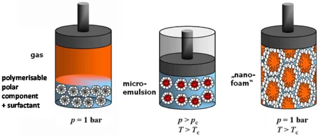
The “Principle of Supercritical Microemulsion Expansion” (POSME) [31, 32] was presented by Schwan, Sottmann and Strey in 2003. Here, thermodynamically stable, nanostructured microemulsions are used as a template. In microemulsions an amphiphilic surfactant film mediates the mixture of two otherwise immiscible components by separating them on the nanoscale. The driving force behind that process is the dramatically decreased interfacial tension. The POSME procedure suggests the use of compressed near- or supercritical fluids which function as hydrophobic component and simultaneously as blowing agent. Thereby, a detailed knowledge of phase behaviour and microstructure of supercritical microemulsions [33-40] is crucial. Fixation, i.e. polymerisation [41-44], and expansion, i.e. an increase of volume, are known to induce demixing process. These are accompanied by coarsening like Ostwald ripening [45] and coagulation with subsequent coalescence [46]. POSME foams display pore sizes in the range of 100 µm [29, 47, 48].
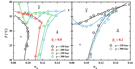
In order to prevent or slow down ageing processes the concept of “Anti-Ageing Agents (AAA) for Nanoporous foams” was developed by Strey et al. [47, 49]. This concept is based on the addition of a low-molecular hydrophobic additive to supercritical microemulsions. It is supposed to accumulate at the thermodynamically unfavourable contact sites of CO2 and the polar component, lowering the interfacial tension. These contact sites emerge due to an increase of volume upon expansion. The influence of the cyclohexane mass fraction in the hydrophobic phase cyclohexane on balanced microemulsions of the type brine – CO2 – fluorinated surfactants has been systematically studied previously as shown in Figure 1.1 left. Note that the efficiency of the system without cyclohexane, i.e.
at cyclohexane = 0.0, strongly depends on pressure. The weight mass fraction needed to formulate a
3 one-phase microemulsion can be considerably reduced by increasing the pressure from 150 to 300 bar.
This is due to an increase of density of CO2 which leads to a reduced interfacial tension with water [50, 51] and an improved surface-to-volume ratio.
Figure 1.1: Left: Plot of the surfactant mass fraction at the point of maximum efficiency against the mass fraction cyclohexane of cyclohexane in the hydrophobic phase, for the balanced microemulsion system H2O/NaCl – CO2/ cyclohexane – Zonyl FSO 100/ Zonyl FSN 100 ( = 0.4, FSN = 0.75, = 0.01). The efficiency increases to a pressure-specific cyclohexane mass fraction but decreases if this concentration is exceeded [52, 53]. Right:
Graphic illustration of the hypothesis of a concentration gradient of cyclohexane in a micelle with fluorinated surfactants. Taken from [52].
Surprisingly, it was found that the partial replacement of CO2 by cyclohexane enables a reduction of fluorinated surfactant by a factor 2 at p = 300 bar and even 5 at p = 150 bar. Here, the higher efficiency at cyclohexane = 0.0 and 300 bar offers less potential improvement than at 150 bar. The repulsive interactions between fluorinated surfactants and protonated substances such as cyclohexane [54, 55] likely reduce the monomeric solubility of fluorinated surfactants in the CO2/cyclohexane mixture, which is rather high (11 wt%) in case of pure CO2 [34].
However, the decreased monomeric solubility and hence increased interfacial area is not sufficient to explain the enormous and unexpected efficiency increase. Thus, a hypothesis to explain this effect was postulated [52] which is shown graphically in Figure 1.1 right. Based on the repulsive cyclohexane/ fluorinated surfactant tails interactions the formation of a depletion zone of cyclohexane close to the surfactants and a cyclohexane-enriched zone at the centre of the domains was postulated. This would result in a concentration gradient of cyclohexane within the respective microemulsion domains. The observed trend of with Figure 1.1 left
might be discussed as follows: Increasing the mass fraction cyclohexane of cyclohexane in the CO2-swollen domains leads to the formation of a depletion zone, which becomes more and more pronounced and causes a considerable decrease of , i.e. an increase of efficiency. This may be caused by improved CO2/ surfactant interactions triggered through repulsive interactions of cyclohexane and the fluorinated surfactant chains. Above a certain (pressure
0.0 0.1 0.2 0.3 0.4
0.0 0.1 0.2 0.3 0.4 0.5 0.6
p = 150 bar p = 200 bar p = 250 bar p = 300 bar
surfactant mass fraction
cyclohexane
˜
Introduction
4 dependent) concentration of cyclohexane, a spatially avoidance of repulsive interactions is no longer possible, causing a decrease of efficiency. At the outset of this work, however, this was only a postulation.
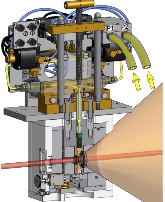
In the context of supercritical microemulsions the investigation of the kinetics of structural changes is a challenge which has so far only been met by Müller et al. [29, 56]. A high-pressure cell for small- angle neutron scattering (SANS) which provides stroboscopic pressure jumps with adjustable amplitude was developed by the mechanical workshop of the University of Cologne within the frame of the BMBF project TISANE [57, 58]. A schematic drawing of this cell is shown in Figure 1.2.
Therein, the key component is a metal bellow (green) which is inserted into the sample volume (orange). By pumping hydraulic oil (yellow) in or out of the bellow it can extend or shrink, respectively, and thus transfer different pressures. Pressure jumps can be performed with a maximum frequency of 5 Hz (status as of March 2013) whereby the maximum pressure is 300 bar. Since the bellow provides nearly unlimited repeatability of pressure jumps this stroboscopic high-pressure SANS cell (SHP-SANS cell) is a unique setup.
Figure 1.2: Cross section of the SHP-SANS cell, prepared by the internal mechanical workshop. The sample volume, which is sealed by two sapphire windows, is marked in orange, where the neutron beam (red) is partly scattered. The pressure jump is performed by means of a metal bellow (green) which can shrink or extend in order to transfer the desired pressure.
Using the SHP-SANS cell the demixing kinetics of a CO2-microemulsion were investigated, showing that they strongly depend on the depth of the pressure jump [29]. In the frame of the anti-ageing project Müller also formulated a diluted microemulsion with 20 wt% cyclohexane in the mixture of cyclohexane and CO2 and found an increase of microemulsion efficiency similar to the one described for balanced microemulsions (see Figure 1.1 left). The reason for this effect, however, was not yet explained. It turned out that the substitution of CO2 by cyclohexane decelerates the demixing process
5 by one order of magnitude. The TISANE option itself, an instrumental setup to investigate kinetic processes with a time resolution < 5 ms, was not yet applied successfully in combination with the SHP-SANS cell. This is due to the fact that the achieved pressure jump frequency (5 Hz) was too slow for the TISANE requirements [29].
Kinetic processes, however, are also important in the area of biomedical applications. Here, understanding drug-release kinetics is of fundamental interest. In this field especially Poly-(N- isopropylacrylamide) (PNIPAM) microgel particles have attracted much attention in recent years.
Their lower critical solution temperature is located around 32°C and therefore very close to the temperature of the human body [59-61]. At this temperature PNIPAM particles undergo a change from swollen microgel to dehydrated spheres due to a change of miscibility with the solvent [62-64]. Co- nonsolvency, which means that PNIPAM particles are soluble in two different solvents (such as water and methanol) but not necessarily in mixtures of both, has also been thoroughly investigated [65, 66].
Besides that other stimuli like pH, salt concentration, solvent composition and also the effect of hydrostatic pressure on the swelling behaviour of microgels were tested [67-69].
However, there are hardly any publications on the kinetics of the volume transition so far, which are crucial for biomedical applications. Admittedly, kinetics according to a change of temperature are difficult to determine. While a rapid heating of the particles can be performed applying for example a Joule-heating temperature jump [70], fast and precise cooling is a challenge. To date, such measurements were only possible by modifying the particles [71, 72]. Utilising small iron oxide particles at the PNIPAM surface rapid magnetic heating can be induced [73]. However, these techniques do not feature a fast repetition as the rebuilding of the initial structure, e.g. by external cooling, is slow. Using co-nonsolvency to induce the structural changes, for example in stopped-flow devices, allows a fast repetition of the experiment [74]. However, since the structural changes are induced by a change of composition the correlation to temperature-induced kinetics is vague.
Recently, it turned out that the transition temperature of thermoresponsive materials can be shifted to higher temperatures by hydrostatic pressure [29, 75]. Consequently, both swelling and deswelling kinetics can be investigated using the SHP-SANS cell. The benefit of hydrostatic pressure is that it can be changed rapidly and reversibly and occurs homogeneously throughout the sample without any gradients like in temperature-changing setups. Such measurements will provide completely new insights into the kinetics of structural changes of thermoresponsive polymers.
The intersection of these two soft-matter systems are consequently microemulsions with polymer particles in the hydrophilic phase. Comparable systems are known as orthogonal self-assembled systems, describing independently coexisting structures [76]. While the most obvious example for such systems are the complex mixtures of structures present in living cells, a variety of systematic studies on less complex systems exists [77-79]. Recently Laupheimer et al. identified a gelled bicontinuous microemulsion as an orthogonal self-assembled system and investigated its phase
Introduction
6 behaviour and microstructure [80, 81]. Unifying articles on both microemulsions and polymer particles commonly deal with particle synthesis using either the high interfacial area or the nanostructure of microemulsions [82-86]. The only study concentrating on the coexistence of microemulsions and PNIPAM particles (Zhou and Wu, 1995) is on the influence of PNIPAM particles on water – hexane – SDS/AOT microemulsions, finding that PNIPAM acts as a stabiliser [87].
Here, the SHP-SANS cell enables not only a detailed investigation of such coexisting structures by means of SANS. It also permits studying the influence of polymer particles on the kinetics of pressure- induced structural changes on microemulsions. Applying appropriate contrast conditions this can also be studied vice versa.
OBJECTIVES
Cyclohexane was found to considerably increase the efficiency of balanced microemulsions of the type brine – CO2 – fluorinated surfactants [29, 52] which is unexpected due to repulsive interactions of hydrophobic protonated and fluorinated substances. The hypothesis of a concentration gradient of cyclohexane with a depletion zone close to the amphiphilic film was postulated but not yet proven [52]. Thus, performing a systematic SANS contrast variation with subsequent detailed analysis of the scattering data was the first goal of this work. The Generalised Indirect Fourier Transformation was to be applied to elucidate the distribution of cyclohexane in such micelles.
Furthermore, a systematic study on the influence of cyclohexane on phase behaviour and microstructure of diluted microemulsions of the same type was planned. It was intended to systematically investigate pressure-induced elongation processes within the thermodynamically stable state at different cyclohexane concentrations. Furthermore, the demixing properties of microemulsions with different cyclohexane contents upon a pressure jump to 70 bar, at which a CO2-in-water microemulsion coexists with a CO2-excess phase, was to be examined.
Besides microemulsions the influence of hydrostatic pressure on different PNIPAM particles was to be studied. Using the SHP-SANS cell should also reveal kinetic aspects of pressure-induced structural changes at temperatures close to the volume phase transition temperature.
Since the focus was on both microemulsions and PNIPAM particles it reasonably follows to also investigate both systems under mutual confinement, i.e. study phase behaviour and microstructure.
Again provided by means of the SHP-SANS cell first SANS experiments regarding kinetic processes under confinement of the respective structure were planned.
Since the SHP-SANS cell is the main tool of this work the improvement of this unique sample holder was an important aspect throughout this work. Especially regarding the possible application of the cell for TISANE measurements it was important to perform faster pressure jumps in order to meet the TISANE principle requirements.
7
2 Fundamentals 2.1 Microemulsions
The first time that a mixture of water – soap – oil was described in dependence of temperature and composition was by Schulman and Hoar in 1943 [88], although the term “microemulsion” was not used until 1959 [89]. Using ionic surfactants, Winsor performed a systematic study of the three-phase region with ionic surfactants [90] and classified four different phase equilibria [91]. The temperature sensitivity of the one-phase microemulsion with non-ionic surfactant was described 1967 by Shinoda [92-95]. Starting from there, the most significant work regarding phase behaviour and microstructure of microemulsions with non-ionic surfactant was performed by Kahlweit and co-workers [96, 97].
Microemulsions are by definition thermodynamically stable, macroscopically homogeneous and isotropic but nano-structured mixtures of at least three components [97-99]. Two of these three components are mutually immiscible, for example a polar one (water, A) and a hydrophobic one (alkane, B). The third, amphiphilic component (C), a surfactant, mediates the mixing by adsorbing at the interface between the immiscible components due to its amphiphilic nature and thus reducing the interfacial tension by several orders of magnitude. For the system water – octane is reduced from 50 mN m-1 [100] to 4.9 · 10-3 mN m-1 upon addition of the surfactant C10E5 [101]. The amphiphilic nature of the surfactant is due to its ambivalent structure. It is composed of the hydrophilic head group which is soluble in polar substances and the hydrophobic tail which is soluble in non-polar oils.
Surfactants can be non-ionic, cationic, anionic, zwitterionic or amphotheric depending on the nature of the polar head group. In this work, only non-ionic surfactants were used. Common commercially available non-ionic surfactants are n-alkyl-polyglycol ether which consist of a tail with i CH2 units and have j glycol units in the polar head group. Thus, they are commonly abbreviated with CiEj.
Although macroscopically a microemulsion is isotropic and homogeneous, on a microscopic scale the two immiscible components are still separated from each other by an extended film of a monolayer of surfactant. Depending on parameters like composition, temperature and, in the case of compressible components, hydrostatic pressure one finds a number of different equilibrium states, and among these occur numerous different structures like spherical droplets or bicontinuous phases. In order to investigate kinetics of structural changes in microemulsions, it is crucial to understand the phase behaviour of microemulsions first.
2.1.1 Phase behaviour of binary mixtures
The binary systems water (A) – oil (B), water (A) – non-ionic surfactant (C) and oil (B) – non-ionic surfactant (C) display characteristic miscibility gaps depending on temperature and composition. A schematic drawing of these systems is shown in Figure 2.1. For the two immiscible components (A) and (B) the miscibility gap can be found over the whole temperature range with the critical point far
Fundamentals
8 above the boiling point of the single components. In the mixture of the hydrophobic component and the non-ionic surfactant only a lower miscibility gap occurs, with an upper critical point cp with its corresponding temperature T which is usually below the freezing point of the mixture [102]. cp and T, however, depend strongly on the nature of the surfactant.
The mixture (A) – (C) also has a lower miscibility gap which is usually well below the melting point of the mixture, and is therefore difficult to measure. More important for microemulsions is the upper miscibility gap which is closed for thermodynamic reasons. Consequently, there is an upper and a lower critical point. The upper critical point usually lies above the boiling point and is therefore not of interest for the phase behaviour of microemulsions. The lower critical point cp, however, is normally in a temperature range which is relevant to microemulsions. The location of this miscibility gap depends on the amphiphilic features of the surfactant and the composition of the polar phase. Between the upper and the lower miscibility gap the surfactant is monomerically dissolved in the polar phase at very low surfactant concentrations. Increasing the surfactant concentration leads to surfactant micelles above the critical micelle concentration (cmc) [103]. If the surfactant concentration is increased further, lyotropic mesophases (´liquid crystals´) occur with almost all types of amphiphiles [104].
Figure 2.1: Schematic drawing of the three binary systems (A)-(B), (A)-(C) and (B)-(C). While (A) and (B) are immiscible over almost the whole temperature range, B and C only have a lower miscibility gap which is often below 0°C. (A) and (C) show a lower miscibility gap, which is lower than the miscibility gap of the system (B)-(C) , and an upper miscibility gap which is relevant to microemulsions. Redrawn from [97].
2.1.2 The phase prism – ternary mixtures
Starting from the triangle shown in Figure 2.2 with the three components at the edges and using the temperature as the ordinate perpendicular to this base triangle, i.e. flipping up the side systems, the Gibbs phase prism is generated. At ternary mixtures, i.e. at compositions between the binary systems
9 at the sides of the prism, many different phases can be observed. The phase behaviour is quite complex and mainly depends on the interplay of the upper miscibility gap of water and non-ionic surfactant and the lower miscibility gap of oil and non-ionic surfactant. Furthermore, the change of solubility of the surfactant from soluble in water at low temperature to soluble in oil at high temperature is a determining factor. This change of solubility can be explained by the partial dehydration of the surfactant head group at high temperature [105].
Figure 2.2: Schematic phase prism of a ternary mixture containing water (A), oil (B) and non-ionic surfactant (C). Highlighted in grey is the three-phase region, in light blue the one-phase region. The test tubes on the right illustrate the different states of 2, 3 and . Redrawn from [106].
The test tubes shown in Figure 2.2 next to the phase prism indicate different possible equilibrium states of the mixture at three different temperatures. Starting at low temperatures, a surfactant-rich oil- in-water (o/w)-microemulsion (ca) coexists with an oil excess phase (b) (lowest test tube). Surfactant molecules are monomerically dissolved in both phases. Since the interactions between water and surfactant are much stronger than the ones between surfactant and oil, the amphiphilic film is curved around the oil. The surfactant-rich microemulsion phase is usually of higher density, so that it is below the oil excess phase. This state is termed 2 to indicate that the lower phase is the surfactant-rich microemulsion.
By increasing the temperature (middle test tube) the interactions of surfactant and polar phase are weakened, which leads to a partial dehydration of the polar head groups of the surfactant. This lowers the solubility of surfactant in the polar phase, until at the temperature Tl the oil-in-water microemulsion splits up to a surfactant-rich microemulsion (ca) and a water excess phase (a) because
Fundamentals
10 the surfactant interacts about equally well with water and oil. The volume of the oil excess phase (b) decreases because more oil can be dissolved in the microemulsion phase (c), which in turn grows in volume. Therefore, three phases coexist at ambient temperatures. Because the surfactant interacts well both with water and oil at ambient temperature the curvature of the microemulsion phase (c) is zero.
By increasing the temperature further (upper test tube) the hydrophobic interactions of surfactant and oil become stronger, and thus the microemulsion phase dissolves more oil until at a certain temperature Tu the microemulsion phase (c) merges with the oil excess phase (b) to a surfactant-rich water-in-oil (w/o)-microemulsion (cb) and a water excess phase (a). As the density of the microemulsion is now usually lower than the one of the water excess phase, the surfactant-rich microemulsion is the upper phase, which is indicated by .
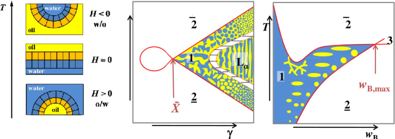
The determination of all phase boundaries in a three-dimensional Gibbs phase prism is complicated and a lot of work. Therefore, it is convenient to use different sections through the phase prim by keeping one ratio constant [99]. Examples are the T() section and the T(wB)-section which are both shown schematically in Figure 2.3.
Figure 2.3: T()-section (left) and T(wB)-section (right) through the upright phase prism. The T()-section shows a variation of temperature and surfactant mass fraction at a constant water-to-oil ratio, whereas the water- surfactant ratio is kept constant in a T(wB)-section. Here, the oil mass fraction wB is varied.
Figure 2.3 left shows a schematic drawing of a T()-section [97, 107]. Here, ratio alpha
Eq. 2-1
of oil in the mixture of water and oil is kept constant and the surfactant concentration is varied, with
being the mass fraction of surfactant in the overall mixture
Eq. 2-2.
Note that it is also common to use volume fractions in order to describe the composition of the sample.
C (non-ionic
surfactant)
C (non-ionic
surfactant)
A (water)
B (oil) 2
1
2 3
T
B (oil)
2
1 2
3 T
wB
A (water) X
wB,max
11 An extended three phase region can be found at low -values and intermediate temperatures. At temperatures below and above the three phase region the two different two phase regions 2 and occur. The three-phase region meets the one-phase region at the so-called optimum point at which the microemulsion is at the optimum state [99] or balanced (from an HLB point of view) [108, 109].
This point is correlated to the optimum temperature T , at which the surfactant has the highest solubilisation properties, and the lowest surfactant mass fraction with which it is possible to formulate a one-phase microemulsion. As is used to characterise the efficiency of the surfactants in the system under investigation, is also called the efficiency point.
As microemulsion changes from oil-in-water to water-in-oil at the temperature T , this temperature is also called phase inversion temperature (PIT) [110, 111]. The phase inversion is founded in the change of solubility of the surfactant. Increasing temperature leads to weaker hydrogen bonds due to more molecular erratic movement [105].
The optimum state is a unique feature for every individual microemulsion composition. The location of the -point is influenced by the hydrophobicity of the oil as well as by the amphiphilic properties of the surfactant. As can be seen in Figure 2.4 left, increasing the hydrophobic chain length from i = 6 to 12, the solubilisation efficiency of the surfactant increases. Furthermore, the higher hydrophobicity leads to a decrease of Tm so that lower temperatures are needed to change the solubility of the surfactant from water-soluble to hydrophobic. On the other hand, an increase of the hydrophilic chain length by varying the number of ethoxy units j between 2 and 7, leads to an increase of Tm which is accompanied by a slight decrease of m.
Figure 2.4: Left: Xm points of various H2O – n-octane – CiEj microemulsions with equal volumes of water and octane as a function of the mean temperature Tm and the surfactant mass fraction m [106]. The numbers in brackets indicate the chain length of the hydrophobic part i and the number of ethoxy units j in the hydrophilic chain in the form of (i, j). Right: Influence of alkanes (CnH2n+2) with different chain lengths on the Xm point in various microemulsions H2O – alkane - CiEj [106]. For all three surfactants, an increase of the chain length of the alkane leads to a shift of the Xm point to higher temperatures Tm and surfactant mass fractions m.
0.0 0.1 0.2 0.3 0.4 0.5
0 10 20 30 40 50 60 70 80
(6,2) (6,4)
(6,3) (8,5)
(8,4)
(10,4) (10,5)
(10,6)
(8,3) (12,6)
(12,7)
(12,5)
Tm[°C]
m (12,4)
0.0 0.1 0.2 0.3 0.4 0.5
0 10 20 30 40 50 60 70 80
14 12 8
10
C8E3 C10E
4
C12E
5
T m[°C]
m 8
10 12
14 8
10 12
14
Fundamentals
12 Figure 2.4 right illustrates the influence of the chain length of the hydrophobic component.
Increasing the length of the alkane (which is indicated by the numbers below the points) leads to a shift of the Xm point to higher temperatures as well as to higher surfactant mass fractions
m. This is mainly due to the fact that longer oils are harder to solubilise. Since the lower miscibility gap within the binary system B-C shifts to higher temperatures with increasing alkane chain length higher temperatures are necessary to drive the surfactant from the water to the oil phase. A similar effect can also be seen for the binary mixture of alkane and surfactant [112].
In contrast to the T()-section, the ratio a
Eq. 2-3
of surfactant in the water-surfactant mixture is kept at a constant value in a T(wB)-section (Figure 2.3 right). Here, the mass fraction of oil is varied. Accordingly, the composition of the sample is given by the mass fraction
Eq. 2-4
of oil (mB) in the overall mixture. At low wB the whole amount of oil can be solubilised by the water- surfactant mixture and the one-phase region stretches over a wide range of temperature. At higher oil mass fractions, the two different two-phase regions also occur, whereby the phase sequence is similar to the one already mentioned for T() sections. The point of maximum efficiency here is wB,max at Tl
and characterises the maximum amount of oil which can be solubilised by the given water-surfactant mixture. The lower phase boundary which separates the one-phase microemulsion from the 2 state is called oil emulsification failure boundary (oefb) [113, 114]. The upper phase boundary very often runs through a minimum at low wB which is caused by the miscibility gap of the binary mixture water- surfactant for surfactants with high amphiphilic strength [98, 115]. Because of its proximity to the critical point of the binary mixture the upper phase boundary is also called the near critical boundary (ncb). In this case, a closed loop miscibility gap causes an unstable microemulsion which separates.
The reasons for this closed loop are discussed in the following chapter.
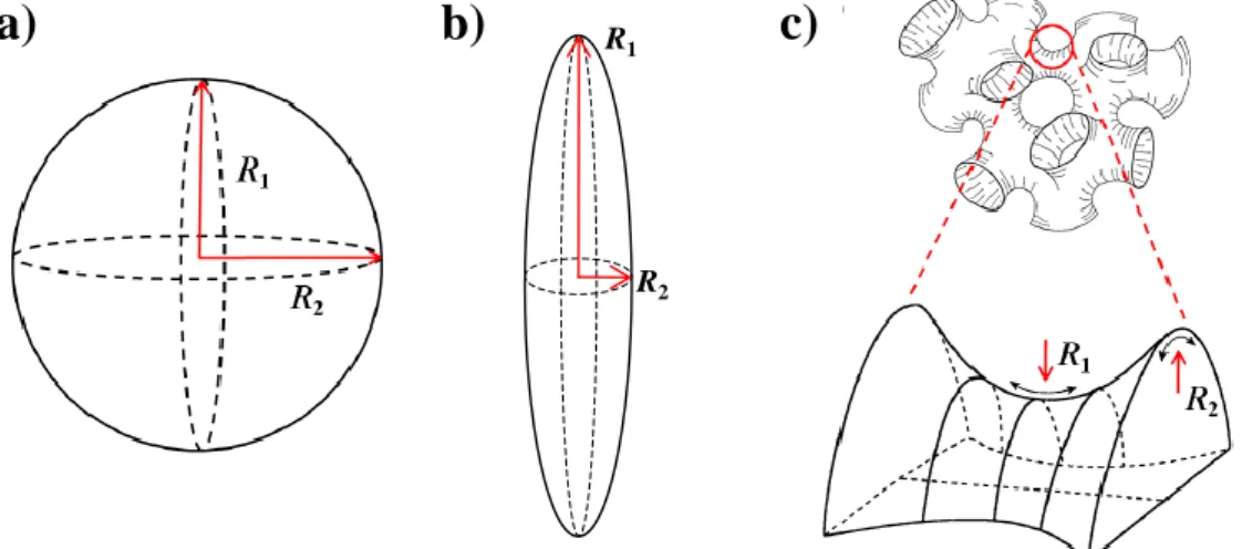
2.1.3 Curvature of the amphiphilic film and microstructure
The most crucial point to predict the phase behaviour is the nature of the surfactant. Depending on the strength of its interactions with the hydrophilic and the hydrophobic phase a local curvature of the amphiphilic film develops [98]. Starting from the two principle radii R1 and R2 the curvatures ci can be described by
and Eq. 2-5