High-Rate Performance of Muon Drift Tube Detectors
von
Philipp Schwegler
eingereicht an der
Fakultät für Physik
der
Technischen Universität München
erstellt am
Max-Planck-Institut für Physik (Werner-Heisenberg-Institut)
München
Juni 2014
Max-Planck-Institut für Physik (Werner-Heisenberg-Institut)
High-Rate Performance of Muon Drift Tube Detectors
Philipp Schwegler
Vollständiger Abdruck der von der Fakultät für Physik der Technischen Universität München zur Erlangung des akademischen Grades eines
Doktors der Naturwissenschaften (Dr. rer. nat.) genehmigten Dissertation.
Vorsitzender: Univ.-Prof. Dr. A. Ibarra Prüfer der Dissertation:
1. Priv.-Doz. Dr. H. Kroha 2. Univ.-Prof. Dr. L. Oberauer
Die Dissertation wurde am 30.06.2014 bei der Technischen Universität München eingereicht und durch
die Fakultät für Physik am 10.07.2014 angenommen.
collides protons with an unprecedentedly high centre-of-mass energy and luminosity.
The collision products are recorded and analysed by four big experiments, one of which is the ATLAS detector. In parallel with the first LHC run from 2009 to 2012, which culminated in the discovery of the last missing particle of the Standard Model of particle physics, the Higgs boson, planning of upgrades of the LHC for higher instantaneous luminosities (HL-LHC) is already progressing. The high instantaneous luminosity of the LHC puts high demands on the detectors with respect to radiation hardness and rate capability which are further increased with the luminosity upgrade.
In this thesis, the limitations of the Muon Drift Tube (MDT) chambers of the ATLAS
Muon Spectrometer at the high background counting rates at the LHC and performance
of new small diameter muon drift tube (sMDT) detectors at the even higher background
rates at HL-LHC are studied. The resolution and efficiency of sMDT chambers at high
γ-ray and proton irradiation rates well beyond the ones expected at HL-LHC have
been measured and the irradiation effects understood using detailed simulations. The
sMDT chambers offer an about an order of magnitude better rate capability and are
an ideal replacement for the MDT chambers because of compatibility of services and
read-out. The limitations of the sMDT chambers are now in the read-out electronics,
taken from the MDT chambers, to which improvements for even higher rate capability
are proposed.
Abstract v
Contents vii
Introduction xi
1 The ATLAS Experiment at the Large Hadron Collider 1
1.1 Introduction . . . . 1
1.2 The Large Hadron Collider . . . . 2
1.3 The ATLAS Experiment . . . . 4
1.3.1 Detector Components . . . . 6
1.3.2 Trigger and Data Acquisition System . . . . 12
1.3.3 Data Taking and Analysis . . . . 13
1.4 Towards Higher Luminosity . . . . 14
1.4.1 LHC Upgrades . . . . 14
1.4.2 ATLAS Upgrade Projects . . . . 15
2 The ATLAS MDT and sMDT Chambers 17 2.1 Introduction . . . . 17
2.2 Monitored Drift Tube Chambers . . . . 18
2.2.1 Mechanical Design and Functionality . . . . 18
2.2.2 Front-End Electronics . . . . 21
2.2.3 Performance of the ATLAS MDT Chambers . . . . 27
2.2.4 Performance in the Presence of Radiation Background . . . . 30
2.3 Small-Diameter Muon Drift Tube Chambers . . . . 31
2.3.1 Technical Implementation . . . . 32
2.3.2 The sMDT Prototype Chamber . . . . 35
2.3.3 Application of sMDT Chambers in ATLAS . . . . 36
vii
3.4.1 Signal Characteristics . . . . 48
3.4.2 Dead Time Effects . . . . 51
3.4.3 Signal Pile-Up Effects . . . . 53
4 Calibration and Data Analysis Methods 55 4.1 Background Rate Measurement . . . . 55
4.2 Gas Amplification Measurement . . . . 56
4.3 Drift Tube Calibration Methods . . . . 57
4.3.1 Drift Time Measurement . . . . 57
4.3.2 Calibration of the Space-to-Drift Time Relationship . . . . 58
4.3.3 Time Slewing Correction . . . . 59
4.4 Spatial Resolution . . . . 59
4.5 Drift Tube Efficiency . . . . 63
5 MDT Chambers Under Photon Irradiation 65 5.1 Introduction . . . . 65
5.2 Experimental Setup . . . . 66
5.3 Measurements Under Photon Background Radiation . . . . 67
5.3.1 Dead Time Measurement . . . . 67
5.3.2 Afterpulsing . . . . 68
5.3.3 Counting Rate Measurement . . . . 70
5.3.4 Spatial Resolution . . . . 73
5.3.5 Efficiency . . . . 74
6 sMDT Chambers Under Photon Irradiation 77 6.1 Introduction . . . . 77
6.2 Experimental Setup . . . . 78
6.3 Data Acquisition and Ambient Condition Monitoring . . . . 80
6.3.1 Front-End Electronics . . . . 80
6.3.2 Irradiation Conditions . . . . 81
6.3.3 Monitoring of Ambient Conditions and Slow Control . . . . 82
6.4 Data Preparation . . . . 84
6.4.1 Time and Drift Distance Calibration . . . . 84
6.4.2 Time Slewing Correction . . . . 85
6.4.3 Spatial Resolution . . . . 87
6.5 Performance Under Irradiation . . . . 88
6.5.1 Gas Gain Drop . . . . 90
6.5.2 Spatial Resolution . . . . 91
6.5.3 Muon Efficiency . . . . 98
7 sMDT Chambers Under Proton Irradiation 101 7.1 Introduction . . . . 101
7.2 Experimental Setup . . . . 102
7.3 Irradiation Conditions . . . . 103
7.4 Drop of the Gas Amplification . . . . 106
7.5 Data Analysis . . . . 108
7.5.1 Proton Rate . . . . 108
7.5.2 Spatial Resolution and Efficiency . . . . 109
7.6 Results . . . . 110
8 Simulation of High-Rate E ff ects 115 8.1 Introduction . . . . 115
8.2 Simulation Chain . . . . 115
8.2.1 Recorded Signals . . . . 117
8.2.2 Electronics Response . . . . 121
8.3 Simulation of Resolution and Efficiency Under Irradiation . . . . 123
8.3.1 Comparison with Measurements Under Photon Irradiation . . . . 123
8.3.2 Comparison with Measurements Under Proton Irradiation . . . . 123
8.3.3 Simulation of Other Chamber Geometries Under Photon Irradiation . . 126
8.4 Improvements of Signal Processing for High Rates . . . . 127
9 Comparison of the MDT and sMDT Drift Tube Performance 133 9.1 Loss of Gas Amplification . . . . 133
9.2 Spatial Resolution . . . . 134
9.3 Drift Tube Efficiency . . . . 136
Summary 141
Since its start-up in 2009, the Large Hadron Collider (LHC) has delivered integrated luminosities of 5.5 fb
−1at a centre-of-mass energy of 7 TeV and of 22.8 fb
−1at 8 TeV to the ATLAS and CMS experiments. With the recorded data sets, the Standard Model of particle physics has been confirmed in the new energy regime, culminating in the discovery of the last missing Standard Model particle, the Higgs boson, with a mass of about 125.5 GeV.
Evidence for physics beyond the Standard Model has not yet been found despite a huge variety of searches. These will continue with the next LHC run starting in spring 2015 at an increased centre-of-mass energy of 13 TeV and an instantaneous luminosity reaching at least the design value of 1 · 10
34cm
−2s
−1. After a decade of operation, an upgrade of the LHC to the High- Luminosity LHC (HL-LHC) is planned, starting operation in 2025 at an instantaneous luminosity of 7 · 10
34cm
−2s
−1. The high instantaneous luminosity of the LHC results in harsh background radiation conditions and puts tight requirements to the detectors and read-out electronics with respect to radiation hardness and rate capability. At HL-LHC luminosity, the rate capability and lifetime of many detector and read-out electronics components of the LHC experiments will be exceeded, requiring replacement of the components.
In this thesis, the performance of the ATLAS Monitored Drift Tube (MDT) chambers with 30 mm tube diameter and of newly developed drift tube detectors with smaller diameter of 15 mm, called sMDT chambers, at high background rates is studied. The reduced tube diameter of the sMDT chambers yields a significant improvement of the rate capability, while compatibility with the detector services and with the read-out system of the MDT chambers is maintained, which makes the sMDT chambers ideal substitutes for the MDT chambers at HL-LHC.
After an introduction about the LHC and the ATLAS experiment and about the planned luminosity upgrades in chapter 1, the principles of the MDT and sMDT chambers and their technical implementation are described in chapter 2. In chapter 3, the expected background radiation rates in the ATLAS detector and the high-rate phenomena caused by it in the MDT and sMDT drift tubes, including their read-out electronics, are discussed. Chapter 4 describes the calibration and analysis methods used for the tests of the MDT and sMDT chambers under irradiation discussed in chapters 5 to 7. In chapter 8, the simulation of the high-rate effects in the sMDT chambers is discussed. Finally, measurements and simulation are compared and summarised in chapter 9.
xi
1
The ATLAS Experiment at the Large Hadron Collider
1.1 Introduction
This chapter introduces the Large Hadron Collider (LHC) and its experiments, in particular the ATLAS detector. The LHC is a hadron accelerator and collider with a circumference of 27 km located at the European centre for particle physics, CERN. Four big experiments, ALICE, ATLAS, CMS and LHCb, study the products of proton and heavy ion collisions.
ATLAS is a multipurpose high-luminosity experiment which addresses a wide range of physics topics. One of its main goals was the search for the last missing particle of the Standard Model of particle physics, the Higgs boson. Now it is the measurement of the properties of the Higgs boson as well as the search for physics beyond the Standard Model like, for instance, for new particles predicted by supersymmetric extensions of the Standard Model.
This chapter describes the layout of the LHC and of the ATLAS detector mainly based on references [1, 2] and gives a brief outlook on planned high-luminosity upgrades.
1
The tunnel is ring-shaped, consisting of eight straight sections and eight arcs, and is located 45 to 170 m below the surface on a slightly (1.4 %) inclined plane. Two 2.5 km long transfer tunnels connect it to the rest of the CERN accelerator complex (see Figure 1.1) which is used for beam injection.
As proton–proton collider, the LHC contains two separate vacuum pipes with oppositely oriented magnetic fields for the counter-rotating beams. A “twin bore design” was chosen for the superconducting dipole magnets that keep the beams on circular orbits. In this compact design, the two rings are integrated into the superconducting magnets in the same cryostat. The dipole magnets generate a field strength of up to 8.33 T allowing for a maximum proton beam energy of 7 TeV. The proton beams are not continuous but divided into 2808 bunches of 1.15 · 10
11protons each with 25 ns spacing resulting in a collision rate of 40 MHz at design operation of the LHC.
The instantaneous design luminosity of the LHC is L = 1 · 10
34cm
−2s
−1. The event rate of a specific process is given by
dN
dt = σ ( √ s) · L ,
where σ( √ s) is the cross-section of the process which depends on the centre-of-mass energy √ s of the proton beams. The total number of expected events in a time period is given by
N = σ( √ s)
L dt = σ( √ s) · L,
where L denotes the integrated luminosity.
Four of the eight straight sections of the LHC house the big experiments: ALICE, ATLAS, CMS and LHCb. ATLAS [2] and CMS [3] are multipurpose detectors designed to operate at the design centre-of-mass energy of √
s = 14 TeV and luminosities of up to L = 1 · 10
34cm
−2s
−1.
After the achievement of the main goal, the discovery of the Higgs boson [4, 5] as the last missing
particle of the Standard Model, they search for any accessible physics beyond the Standard Model
perform measurements of the properties of the Higgs boson like coupling strengths to fermions
and bosons, CP quantum numbers and total decay width.
CMS
ATLAS
LHC-b
ALICE LHC
PS
SPS
BOOSTER AD
LINAC 2 CTF3
LINAC 3
CNGS
ISOLDE West Area
East Area North Area
Towards Gran Sasso
n-TOF TI2
TT10
TT60
TT2
TI8
protons ions neutrons
antiprotons electrons
neutrinos LHC Large Hadron Collider
SPS Super Proton Synchrotron PS Proton Synchrotron
CNGSCERN Neutrinos Gran Sasso n-TOFNeutron Time Of Flight AD Antiproton Decelerator
CTF3 CLIC TestFacility 3
©CopyrightForthommel/WikimediaCommons/CC-BY-SA-3.0
Figure 1.1: The CERN accelerator complex.
LHCb [6] is an experiment dedicated to b-hadron physics designed for a lower luminosity of L = 1 · 10
32cm
−2s
−1. It performs precision measurements of CP-violation that may help to explain the matter–antimatter asymmetry in the universe and searches for rare B meson decays.
In addition to protons, the LHC can collide lead ions (
208Pb
+82) in lead–lead and lead–proton operating modes at a centre-of-mass energy of √
s = 2.76 TeV per nucleon. At the high energy densities reached in lead–lead collisions, quarks and gluons are expected to form a colour- deconfined state called quark–gluon plasma. The ALICE experiment [7] is devoted to the study of heavy ion collisions at a luminosity of L = 1 · 10
27cm
−2s
−1.
The four big LHC experiments share their interaction points with three additional smaller experiments: LHCf, TOTEM and MoEDAL. LHCf [8] consists of two detectors 140 m from the interaction point on either side of the ATLAS detector and aims for a better understanding of the origin of ultra-high-energy cosmic rays. TOTEM [9] shares the interaction point with CMS and consists of detectors 147 m and 220 m from the collision point. Its goal is the measurement of the total proton–proton interaction cross section and elastic and diffractive scattering processes.
MoEDAL [10], approved in 2010, is the youngest of the LHC experiments. Its goal is the search
for magnetic monopoles and other strongly ionising massive particles.
Figure 1.2: The ATLAS experiment at the Large Hadron Collider [2].
1.3 The ATLAS Experiment
The ATLAS detector is a multipurpose detector designed to explore a wide range of physics topics.
The unprecedented energy and luminosity of the LHC allow for both precision measurements of the Standard Model on QCD, electroweak interactions and flavour physics and searches for any conceivable new physics processes beyond the Standard Model.
The high interaction rate puts, however, strong demands on the detectors and electronics in terms of radiation tolerance and spatial and time resolution. The production cross-sections of most interesting processes are many orders of magnitude smaller than the total inelastic proton–proton cross-section of about 80 mb which is dominated by dijet production. At design luminosity, with 40 MHz bunch crossing rate, each interesting event is accompanied by on average 23 inelastic events. Highly granular, radiation hard detectors and electronics are needed to cope with the high radiation levels and track density to control the effects of overlapping events. As the read-out and storage capacity is limited, a very selective and efficient trigger system is required to arrive at a manageable data volume without discarding interesting rare events.
High resolution electromagnetic calorimetry is important for efficient electron and photon
identification and precise energy measurement. Hermetic hadronic calorimetry is essential for
accurate jet and missing transverse energy measurements which are fundamental for many studies.
Figure 1.3: The superconducting solenoid (blue) and toroid (red) magnet coils [2].
The ATLAS detector, depicted in Figure 1.2, is forward–backward symmetric with respect to the interaction point. The individual sub-detectors are arranged cylindrically around the beam pipe in the central barrel region and in discs in the so-called end-caps, typical for many collider experiments.
The superconducting magnet system consisting of a thin solenoid coil surrounding the inner tracking detector with a length of 5.3 m and a diameter of 2.5 m and three large air-core toroids (one for the barrel and one for each end-cap) in the Muon Spectrometer determines the size and geometry of the detector. The layout of the magnet system is shown in Figure 1.3.
ATLAS uses a right-handed coordinate system with its origin at the nominal interaction point
in the centre of the detector and the z-axis along the beam line. The x-axis points from the
interaction point to the centre of the LHC ring and the y-axis is directed upwards. Cylindrical
coordinates (r , θ, φ) are used in the transverse plane, where φ is the azimuthal angle around
the beam line, θ the polar angle and r the radius measured from the beam line. Transverse
observables (index “T ”) are projections into the x– y plane perpendicular to the beam line. For
many applications, the pseudorapidity is used as replacement of the polar angle θ given by
η = − ln tan
θ/
2.
E
⊕ ≤
forward σ
E/E = 100 %/ √
E ⊕ 10 % 3.1 < | η | < 4.9 Muon spectrometer σ
pT/p
T= 10 % at p
T= 1 TeV ≤ 2.7 ( ≤ 2.4)
= 3 % at p
T= 100 GeV
1.3.1 Detector Components
This section describes the sub-detectors of the ATLAS experiment. The performance specifica- tions of the individual subsystems in terms of energy and momentum resolution and pseudorapid- ity coverage are summarised in Table 1.1.
The Inner Tracking Detector
About 1000 particles emerge from a proton collision at the LHC leading to a high density of tracks in the detector. ATLAS uses a combination of three technologies in the Inner Detector (ID)
— silicon pixel and micro-strip (SCT) detectors and a Transition Radiation Tracker (TRT) — to achieve the required momentum and vertex resolutions. The ID is immersed in a 2 T magnetic field created by the central solenoid. The overall layout of the ID is illustrated in Figure 1.4.
The innermost component is the Pixel Detector arranged around the interaction point in three concentric cylinders in the barrel region and disks perpendicular to the beam line in the end-cap regions. The spatial resolution provided by the Pixel Detector is 10 µm in the transverse plane and 115 µm in the longitudinal direction with respect to the beam line. The innermost detector layer is at a distance of only 5 cm from the beam line and is especially important for the measurement of decay vertices needed for b-quark and τ-lepton identification as well as for searches for new long-lived particles. The Pixel Detector has approximately 80.4 million read-out channels.
In a similar layout but with four layers, the Semiconductor Tracker SCT (Semiconductor Tracker) surrounds the Pixel Detector. It uses silicon micro-strip sensors with an average strip pitch of 80 µm assembled back-to-back with a stereo angle of 40 mrad in each layer to measure track coordinates with a resolution of 17 µm in transverse and 580 µm in longitudinal direction.
Both the Pixel and the SCT detectors cover the pseudorapidity range | η | < 2.5.
Figure 1.4: The ATLAS Inner Detector [2].
The outermost component of the ID is the TRT consisting of 4 mm diameter straw drift tubes made of 35 µm thick Kapton with 31 µm diameter gold-plated tungsten anode wires operated with Xe/CO
2/O
2(70/27/3) gas at 5 to 10 mbar over-pressure. The TRT provides on average 36 coordinates per track with a resolution of 130 µm in transverse direction over a pseudorapidity range of | η | < 2.0. Transition radiation photons from electrons traversing the polypropylene fibres and foils with which the straws are interleaved ionise the Xenon gas yielding much larger signals than minimum-ionising particles and thus providing electron identification. The large number of hits per track allows for robust pattern recognition.
The Calorimeters
The ATLAS calorimeter system consists of electromagnetic and hadronic sampling calorime- ters covering the pseudorapidity range | η | < 4.9. The total thickness of the electromagnetic calorimeters is more than 22 radiation lengths. Approximately 11 nuclear interaction length of the whole calorimeter system sufficiently reduce the punch-through into the Muon Spectrometer.
The high containment of hadrons together with the large η-coverage enables high jet and missing
transverse energy resolution which are crucial for a hadron collider experiment. An overview of
the calorimeter system is given in Figure 1.5.
Figure 1.5: The ATLAS calorimeter system [2].
Electromagnetic Calorimeters The electromagnetic calorimeter uses liquid argon (LAr) as active medium and lead absorber material in a barrel part and two end-cap parts, each housed in their own cryostats. The barrel part shares the vacuum vessel with the superconducting solenoid magnet it surrounds minimising the amount of dead material which deteriorates the energy resolu- tion. Each end-cap consists of two coaxial wheels. All parts consist of radially accordion-shaped lead absorber plates and Kapton electrodes. The accordion geometry provides homogeneous azimuthal response and electronics connections at the outer diameter. The absorber plate thick- ness is optimised for energy resolution as a function of η . For | η | < 2.5, the electromagnetic calorimeter is segmented into three sections in depth, while in the more forward regions there are only two sections in depth and also the lateral granularity is reduced. In the range | η | < 1.8, a highly segmented LAr presampler is used to correct for energy loss upstream of the calorimeter.
Hadronic Calorimeters The hadronic calorimeter consists of a barrel and two end-cap parts
supplemented by a forward calorimeter. The barrel Tile Calorimeter with its extensions uses
steel as absorber and scintillating tiles as active medium and covers the ranges | η | < 1.0 and
0.8 < | η | < 1.7, respectively. Both the barrel and the extended barrels are segmented into 64
modules azimuthally and three sections in depth. The scintillating tiles are read out on two sides
by photomultiplier tubes via wavelength shifting fibres. The hadronic end-cap LAr calorimeter
is located directly behind the electromagnetic end-cap calorimeter and shares the same cryostat.
It consists of two wheels on each side, each consisting of 32 wedge-shaped modules. Copper plates, 25 mm thick in the inner and 50 mm thick in the outer wheel, are used as absorber material, separated by 8.5 mm wide LAr gaps.
The forward calorimeter shares the cryostats with the end-cap calorimeters and covers the range 3.1 < | η | < 4.9. It is recessed by about 1.2 m with respect to the front of the electromagnetic calorimeter in order to reduce neutron albedo into the inner detector. It also uses LAr as the active medium and consists of three modules in longitudinal direction. The innermost module optimised for electromagnetic measurements uses copper absorbers, the other two optimised for measurements of hadronic interactions use tungsten absorbers. A matrix of longitudinal channels filled with LAr as active medium is embedded into the absorber materials.
The Muon Spectrometer
The main characteristic of the ATLAS detector is the Muon Spectrometer which defines the overall size of the detector with 44 m in length and 25 m in diameter. It measures the deflection of muon tracks in the magnetic field generated by large superconducting air-core toroid magnets and is designed to provide a highly efficient muon trigger and high-precision muon momentum measurement up to the TeV scale. The air-core magnet design minimises the degradation of the momentum resolution due to multiple scattering. An overview of the Muon Spectrometer is given in Figure 1.6.
The Muon Spectrometer is subdivided into the barrel part ( | η | < 1.4), where the toroidal magnetic field is provided by the eight 20 m long superconducting coils and two end-caps (1.6 < | η | < 2.7), where the magnetic field is provided by two separate superconducting toroid magnets. In the transition region between the barrel and the end-caps (1.4 < | η | < 1.6), there is a superposition of the barrel and end-cap toroid fields. While the eight barrel toroid coils are housed in individual cryostats assembled symmetrically around the beam line, the end-cap toroid coils on either side of the detector share a common cryostat. The eight end-cap toroid coils are rotated by 22.5° with respect to the barrel toroid coils in order to provide radial overlap and improve the bending power in the transition region (see Figure 1.3). The magnetic field is mostly perpendicular to the muon trajectories and provides a bending power in the range from 1 to 7.5 T m.
Dedicated detectors for precision tracking and triggering are arranged in three cylindrical
layers around the beam axis in the barrel and in three wheels in the end-cap regions. The
majority of the precision tracking chambers are Monitored Drift Tube (MDT) chambers which
are described in detail in the following chapter as they form the framework of this thesis. Only
Figure 1.6: The ATLAS Muon Spectrometer [2].
in the inner end-cap layer at large pseudorapidity (2.0 < | η | < 2.7), where the particle flux is too high for the MDT chambers, Cathode Strip Chambers (CSC) with higher granularity and faster response are used. In total, 1150 MDT chambers with 350 000 drift tubes and 32 CSCs with 31 000 channels cover the pseudorapidity range | η | < 2.7.
Resistive Plate Chambers (RPC) are used as trigger detectors in the barrel region while Thin Gap Chambers (TGC) are used in the end-caps. Besides providing a fast trigger decision, the trigger chambers provide bunch crossing identification and measurement of the second coordinates of the muon tracks in the direction of the drift tubes of the MDT chambers. The spatial resolution is only on the order of 1 cm.
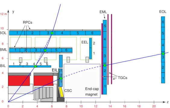
Figure 1.7 illustrates the principle of the muon trigger. The muon momentum measurement
of the trigger chambers is based on the angular deviation between a straight line connecting a
hit in the so-called pivot or reference plane with the nominal interaction point and a straight line
connecting the hit in the pivot plane with a hit in one of the other two detector layers. In the barrel
region, the pivot plane is the middle RPC layer (RPC2) while in the end-caps it is the outermost
TGC layer (TGC3). Depending on whether the second hit is in the close or in the distant layer,
one obtains a low- or a high-p
Ttrigger. An additional fourth TGC layer in front of the end-cap
toroid magnet is used to reduce the number of fake triggers from tracks not originating from the
Figure 1.7: Illustration of the Level-1 muon momentum trigger in one quadrant of the detector cross section containing the beam line, three layers of RPCs in the barrel and 3 layers of TGCs in the middle end-cap wheel. The p
T-thresholds are defined by deviations of the track from a straight line connecting the track point in a reference or pivot plane and the interaction point.
The pivot plane in the barrel is the middle RPC layer and in the end-caps the outermost TGC
layer. The other two layers, RPC1 or RPC3 and TGC1 or TGC2, are used for low-p
Tand high-p
Ttrigger thresholds, respectively [2].
2 4 6 8 10 12 14 16 18 20 2
4
0 BIL
CSC
1 2
0
1 2 3 4 5 6
TGCs 1
2 1
2
3
z End-cap
magnet EIL
Figure 1.8: Illustration of the muon momentum measurement in the ATLAS Muon Spectrometer.
interaction point.
Figure 1.8 illustrates the precision muon momentum measurement. In the barrel region it is based on the measurement of the track sagitta from hits in three muon detector layers while in the end-cap regions a point in the inner layer (EI) and a polar angle measurement are used for each track.
Precise knowledge of the magnetic field and of the relative chamber positions is essential to achieve the desired momentum resolution of σ
pT/p
T= 10 % for 1 TeV muons. The alignment of the precision tracking chambers, both internally and with respect to each other, relies on an optical alignment monitoring system combined with chamber position measurement using straight muon tracks while the magnetic field is turned off. The magnetic field is measured with approximately 1800 Hall probes in the muon spectrometer volume.
1.3.2 Trigger and Data Acquisition System
ATLAS uses a three-level trigger system to reduce the event rate from the 40 MHz bunch crossing rate to approximately 200 Hz written to tape. The first trigger level (L1) is implemented in custom- made electronics. The second (L2) and third (Event Filter) levels use commercial computer farms.
The L1 trigger (see Figure 1.9) takes decisions within 2.5 µs and reduces the event rate to
about 100 kHz. It searches for high transverse momentum muons, electrons, photons, jets and
Calorimeter triggers EM Jet
ET
Muon trigger
Detector front-ends L2 trigger Central trigger
processor
Timing, trigger and control distribution
Calorimeters Muon detectors
DAQ L1 trigger
Regions- of-Interest ETmiss
τ µ
Figure 1.9: Schematic of the first level (L1) trigger [2].
τ-leptons decaying into hadrons as well as for events with large transverse energy or large missing transverse energy using information from the RPC and TGC muon trigger chambers and from the calorimeters with reduced granularity. The L1 decision is taken by the Central Trigger Processor (CTP) which also provides selection criteria like passed thresholds and regions-of-interest (RoI) information to the L2 trigger.
The L2 trigger uses the RoI information provided by the L1 trigger as seeds for the processing of the full detector information with simplified reconstruction programs within the RoIs. It reduces the event rate to about 3.5 kHz with an average processing time of 40 ms.
The final event selection is performed by the third stage, the “Event Filter”, which uses the full ATLAS event reconstruction software. It reduces the event rate to 200 Hz with a typical processing time of four seconds per event. With an average event size of 1.3 MB, the average output bandwidth is almost 300 MB/s.
1.3.3 Data Taking and Analysis
During the first period of operation from 2010 to 2012, now called Run 1, the LHC has delivered integrated luminosities of L = 5.5 fb
−1at a centre-of-mass energy of √
s = 7 TeV and of L = 22.8 fb
−1at √
s = 8 TeV to the ATLAS and CMS experiments [11].
With the recorded data sets, the Standard Model (SM) of particle physics has been confirmed
in the new energy regime culminating in the discovery of the last missing SM particle, the Higgs
LHC b b b b b b b b b b b bo o o o o oo o o o o o o o oo o o o o o o o oo o o o o o o o o o o o o o o o o o oo o o o o o o o oo o o o o o o o oo o o o o o o o o o o o o o o o o oo o o o o o o o oo o o o o o o o oo o o o o o o o o b b b b b b b b b b b bo o o o o oo o o o o o o o oo o o o o o o o oo o o o o o o o o o o o o o o o o oo o o o o o o o oo o o o o o o o oo o o o o o o o o
Injectors b b b b b b b b b b b bo o o o o oo o o o o o o o oo o o o o o o o oo o o o o o o o o o o o o o o o o o o oo o o o o o o o oo o o o o o o o oo o o o o o o o o o o o o o o o o o oo o o o o o o o oo o o o o o o o oo o o o o o o o o b b b b b b b b b b b bo o o o o oo o o o o o o o oo o o o o o o o oo o o o o o o o o o o o o o o o o o oo o o o o o o o oo o o o o o o o oo o o o o o o o o
2029 2030 2031 2032 2033 2034
Q2 Q3 Q4 Q1 Q2 Q3
2035 Q1 Q2 Q3 Q4 Q1 Q2 Q3 Q4 Q1 Q4 Q1 Q2 Q3 Q4 Q1 Q2 Q3 Q4 Q1 Q2 Q3 Q4
LS 4 Run 5 LS 5
Figure 1.10: CERN LHC and HL-LHC schedule [15].
boson, in 2012 [4, 5] with a mass of m
H≈ 125.5 GeV [12, 13] and rate compatible with the SM prediction.
Despite a huge variety of searches, no evidence for physics beyond the Standard Model has been found yet. The searches will continue with LHC Run 2 in 2015 at an increased centre-of- mass energy of 13 TeV.
Whether or not new physics will be found in Run 2, an increase of the integrated luminosity is desirable to study the still open questions of the Standard Model like the naturalness or hierarchy problems or the origins of dark matter and of the matter–antimatter asymmetry.
1.4 Towards Higher Luminosity
1.4.1 LHC Upgrades
During Run 2, which is planned to last from mid 2015 to mid 2018, the LHC will reach the design luminosity and energy. After the so-called Phase-I upgrades of the LHC with improvements to the injectors including a new linear accelerator LINAC4 [14] replacing the current LINAC2 (see Figure 1.1), the instantaneous luminosity will be doubled to 2 · 10
34cm
−2s
−1. In this configuration, the LHC will be operated until 2023 and deliver at least 300 fb
−1of proton–proton collisions to the ATLAS and CMS experiments.
After Phase-II upgrades from 2023 to 2025, the LHC will reach an instantaneous luminosity of
7 · 10
34cm
−2s
−1(High-Luminosity LHC or HL-LHC) and deliver 3000 fb
−1within the following
ten years.
1.4.2 ATLAS Upgrade Projects
With the increase of the instantaneous luminosity beyond the design value and extended running time, the LHC experiments need to adapt to the higher demands on rate capability, radiation hard- ness, particle multiplicities and trigger selectivity in order to benefit from the higher luminosity.
This section gives an overview of planned ATLAS upgrade projects in the coming decade. The goal of the upgrades is to at least maintain and even improve upon the design performance at the higher luminosity.
Detector Consolidation Phase-0
The biggest upgrade project during the first long LHC shutdown (2013–2014) is the installation of the “Insertable B-Layer” (IBL), a fourth layer added inside the present pixel detector on a new beam pipe [16]. The IBL improves the decay vertex reconstruction and hence the b-hadron and τ-lepton identification and compensates for deterioration of present pixel detector due to radiation damage.
The other important upgrade project is the installation of additional muon tracking chambers to improve the momentum resolution in a so far poorly instrumented region of the barrel Muon Spectrometer [17]. A new type of smaller diameter drift tube (sMDT) chambers is used which will be described in the next chapter.
Phase-I Upgrades
The Phase-I upgrades of the Muon Spectrometer in 2018–2019 anticipate necessary improvements for HL-LHC [18]. The main project is the replacement of the inner end-cap layer of the Muon Spectrometer, the so-called Small Wheel, by the New Small Wheel (NSW) using detector technologies with higher rate capability and spatial trigger detector resolution [19].
Phase-II Upgrades
The Phase-II upgrades are planned for 2022–2024 and enable efficient operation at HL-LHC conditions for additional ten years to collect collision data corresponding to 3000 fb
−1[20].
Complete replacement of the inner tracking detector, which reaches the end of its lifetime after 400 fb
−1, is required. The new tracker has to deal with a much higher track multiplicity from up to 200 interactions per bunch crossing and tolerate more than an order of magnitude higher radiation doses.
To limit the trigger rate without discarding interesting events, the selectivity of the L2
trigger has to be reached already at L1. With trigger latencies above 30 µs, inner detector
2
The ATLAS MDT and sMDT Chambers
2.1 Introduction
This chapter introduces the ATLAS Monitored Drift Tube (MDT) chambers used as precision tracking detectors in the current ATLAS Muon Spectrometer and a new type of drift tube chambers with smaller tube diameter called sMDT chambers developed for upgrades of the muon detector.
MDT and sMDT chambers consist of several layers of drift tubes operated in proportional mode with low gas amplification in order to prevent ageing. Knowing the time when a muon passes the detector, the drift time of the primary ionisation electrons can be measured in each drift tube and translated into a drift radius. The chambers are designed to provide a spatial resolution of 35 µm in order to achieve the desired muon momentum resolution in the Muon Spectrometer.
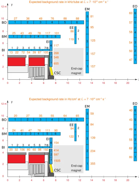
The ATLAS MDT chambers are exposed to unprecedentedly high photon and neutron background irradiation with counting rates of up to 500 Hz/cm
2. The chamber resolution and efficiency degrade due to the background radiation rates which increase with the LHC luminosity.
Hence, a new type of MDT chambers with reduced tube diameter and, therefore, higher rate capability, the sMDT chambers, has been developed. In addition, the sMDT chambers are more compact allowing for the instrumentation of confined detector regions.
17
The basic components of the MDT chambers are aluminium drift tubes with 29.970 mm outer diameter and 400 µm wall thickness filled with Ar/CO
2(93/7) gas at 3 bar absolute pressure
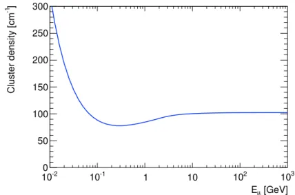
∗. Electrons created by ionisation of the Argon atoms by traversing charged particles drift towards a gold-plated tungsten-rhenium anode wire with 50 µm diameter which is kept at a potential of +3080 V with respect to the tube walls (see Figure 2.1). The ionisation is a stochastic process.
Clusters of electron–ion pairs are created along the muon path with a density of around 100 cm
−1(cf. Figure 2.2) and a typical size of 3 electron–ion pairs.
Within about 150 µm of the wire, the drifting ionisation electrons gain enough kinetic energy in the radial electric field between collisions that they ionise further Argon atoms in an avalanche multiplying the primary ionisation charge by a factor of 2 · 10
4, the gas amplification or gas gain. With the knowledge of the time when the muon passed the tube from an external source
— in the case of ATLAS this is the bunch crossing time delivered by the LHC corrected for the time-of-flight of the muon from the interaction point to the detector and propagation times
— one can determine the electron drift time by measuring the avalanche arrival time at the wire. The drift time can be translated into the drift radius at which the muon crossed the tube, once the space-to-drift-time relationship r (t) has been determined using dedicated calibration algorithms [24–26].
The tube gas volume is sealed by end-plugs consisting of insulating plastic (Noryl) and a central brass insert that holds the anode wire concentrically with respect to the aluminium reference rings with an accuracy of 10 µm (see Figure 2.1). The wire tension is adjusted with high accuracy to (350 ± 15) g during the tube assembly to define the wire sag and the wire position over the whole tube length with an accuracy of 10 µm. The metal inserts also facilitate gas inlet and outlet and the electrical signal and high-voltage connections on opposite tube ends. The main MDT chamber parameters are summarised in Table 2.1
With few exceptions, the MDT chambers are composed of two multilayers of drift tubes separated by support frames (see Figure 2.3) consisting of three cross plates interconnected
∗About 500 ppm of water are added to the gas mixture to increase the high-voltage stability and avoid cracking of the end-plugs due to drying out. The influence on the drift properties is negligible.
Ground pin
O-ring 10 × 1.5
Reference ring
Stopper Wire locator O-ring 23.47 × 2.62 End-plug body
Central insert Gas jumper
O-ring 10 × 1.5 Crimp tubelet
Signal cap
(a)
µ
29.970 mm Anode wire Cathode tube
Rmin
(b)
Crimp wire-fixation (copper)
Plastic insulator (Noryl)
Aluminum tube
O-ring seal
Aluminum ring (external reference)
Ground connection Precision wire-locator
(brass)
(c)
Figure 2.1: Exploded view of the MDT end-plug (a) and cross sections of an MDT drift tube in (b) transverse and (c) longitudinal direction [2].
Table 2.1: MDT chamber parameters [2]
Parameter Design value
Tube material Aluminium
Outer tube diameter 29.970 mm
Tube wall thickness 0.4 mm
Wire material Gold-plated W/Re
Wire diameter 50 µm
Gas mixture Ar/CO
2/H
2O (93/7/ ≤ 1000 ppm)
Gas pressure 3 bar (absolute)
Gas gain 2 · 10
4Wire potential +3080 V
Maximum drift time 760 ns
Average drift tube spatial resolution 80 µm
(with time slewing correction)
[GeV]
Eµ
10-2 10-1 1 10 102 103
0 50
Figure 2.2: Cluster density as a function of the muon kinetic energy at nominal MDT operating parameters (see Table 2.1)
by two long beams in tube direction. An optical alignment system mounted on the support frame is used to monitor deviations from planarity under gravitational sag, mechanical stress and thermal gradients [27]. The MDT chambers in the barrel region are rectangular while they have trapezoidal shape in the end-caps.
The drift tubes are glued together in the multilayers with a wire positioning precision of better than 20 µm. The chambers in the middle and outer layer of the Muon Spectrometer have three drift tube layers per multilayer, while the chambers in the inner layer consist of four tube layers per multilayer to cope with the higher radiation background.
The middle cross plate can be moved with respect to the outer ones to compensate for the gravitational sag of the chambers and adjust it to the sag of the anode wires in order to maintain concentricity with the tube wall over the whole tube length.
To achieve a stand-alone muon momentum resolution of the Muon Spectrometer of σ
pT/p
T≈ 10 % for transverse momenta of p
T= 1 TeV, the MDT chambers have been designed to reach a spatial resolution of 35 µm, which requires knowledge of the wire positions within a chamber of better than 20 µm and an average single-tube resolution of 80 µm. The drift tube resolution will be discussed in more detail below.
In order to achieve this resolution, variations of the operating parameters, like temperature,
gas pressure and composition and the magnetic field strength, have to be monitored with high
precision and taken into account in the calibration of the r (t) relation.
RO
HV
Drift tube layers
Length: 1–5 m
Width : 0.7–2
.2 m
Alignment rays
Figure 2.3: Schematic view of an ATLAS MDT chamber in the barrel region [2].
2.2.2 Front-End Electronics
The MDT front-end electronics comprises passive signal and high-voltage distribution boards, active read-out boards and detector control and monitoring units. A photograph of the MDT on-chamber electronics components is shown in Figure 2.4.
Passive Electronics Boards
Figure 2.5 gives an overview of the services connected to the drift tubes. The electrical connections to the anode wires and the tube walls are provided by passive so-called hedgehog boards via signal caps and ground pins on the end-plugs (see Figure 2.1). Each hedgehog board connects to 3 × 8 tubes in three-layer multilayers, and to 4 × 6 tubes in four-layer multilayers.
On the chamber end, the high-voltage hedgehog boards connect the tubes to the high-voltage supply via a 383 Ω terminating resistor matching the tube impedance and a low-pass filter composed of a 1 MΩ resistor and a 470 pF capacitor cutting off noise with frequencies >500 Hz.
The 1 MΩ resistor also limits the current in case of a short, e.g. caused by a broken wire, until the
high-voltage has been switched off. Additional low-pass noise filters with a cut-off frequency
of approximately 725 Hz are installed close to the chamber in the high-voltage supply lines
connecting each tube layer individually to further suppress pick-up noise. The circuit diagram is
shown in Figure 2.6.
(3) (4) (6) (5)
Figure 2.4: Photograph of the read-out end of an 2 × 3 layer MDT elx where the different electronics components are visible in sections of 3 × 8 tubes. In section (1) the bare tube ends with signal caps screwed on the end plugs and the gas supply tubelets are visible. Section (2) shows a signal hedgehog board attached to the tube ends via pins on the signal caps. In section (3) a mezzanine board is plugged onto the hedgehog board shielded by the inner Faraday cage cover In section (4) the mezzanine board is enclosed in its own Faraday cage and connected via the blue shielded twisted-pair cable to the Chamber Service Module (CSM) (5), which collects the data from the drift tubes of a chamber and transmits it via an optical fibre cable to the data acquisition system. The red box (6) is the Muon Detector Control Module (MDM) [28].
n
Figure 2.5: Electrical connections to an MDT drift tube. On the high-voltage side, the wire
is terminated with the drift tube impedance of 383 Ω to avoid signal reflections. All electrical
contacts between the tubes and the hedgehog boards (marked by dots) are gold-plated to ensure
long-term stability [28].
In Out 25 kΩ
25 kΩ
2×2200 pF/6 kV DC +
−
Figure 2.6: Circuit diagram of the noise filters used in the high-voltage connections to suppress pick-up noise [29].
Table 2.2: ASD analog specifications [30]
Input impedance Z
in= 120 Ω
Noise σ
ENC= 6000 e
−equiv. to 5 primary e
−(pe
−) (at gas gain 2 · 10
4)
Shaping function bipolar
Shaper peaking time t
p= 15 ns
Sensitivity at discriminator input 1.65 mV/pe
−(at gas gain 2 · 10
4) equiv. to 8.9 mV/fC Linear response range 1.5 V or 900 pe
−Nominal discriminator threshold 40 mV or 24 pe
−(equiv. to 5 σ
ENC)
On the signal hedgehog boards on the opposite chamber end, a 470 pF capacitor decouples the read-out boards from the high-voltage. Two resistors form a protection network for the attached mezzanine boards carrying the active front-end electronics.
Active Front-End Electronics
Each signal hedgehog board is connected to a mezzanine board containing the ASD (Ampli- fier/Shaper/Discriminator) and TDC (Time-to-Digital Converter) chips.
The ASD [30] contains fully differential preamplifier, shaper and discriminator stages for 8 channels with the main specifications summarised in Table 2.2. Each mezzanine board contains 3 ASD chips for in total 24 drift tubes. Bipolar shaping was chosen in order to avoid baseline shift at high counting rates (see section 3.4). Figure 2.7 shows a block diagram of one ASD channel.
After passing the amplification and shaping stages, the signals pass a discriminator (DISC1) with programmable threshold. The first threshold crossing time defines the arrival time of the signal.
The ASD can be operated in charge measurement (ADC) or time-over-threshold (ToT) mode.
In ToT mode, the ASD digital (LVDS) output signal length corresponds to the time the analogue
signal exceeds the threshold while in ADC mode it corresponds to the signal charge. The
main application of the charge measurement is correction for time slewing, the dependence of
the threshold crossing time on the signal amplitude. Smaller signals cross the discriminator
threshold later than large signals resulting in a systematic variation in the drift time. Time slewing
corrections using the charge measurement are described in section 4.3.3.
Calibration System Control Logic (JTAG Interface)
Charge
2
Figure 2.7: Block diagram of one ASD channel [28] (see text). The ASD chip can be operated (1) in time-over-threshold or (2) charge measurement mode.
The signal amplitude is measured by the charge in the rising edge with a Wilkinson ADC (Analogue-to-Digital Converter), hence a short integration gate with default width of 18.5 ns is used. The MDT signals can have a complicated shape and extend up to the maximum drift time of the tubes of 760 ns due to afterpulses of subsequently arriving ionisation clusters (see below).
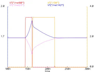
Figure 2.8 shows the response of the Wilkinson ADC. A holding capacitor is charged during the integration time window, which is opened when the discriminator threshold is crossed.
At the end of the integration gate, the rundown gate is opened and the holding capacitor is discharged with constant current until it falls below the threshold of a second discriminator (DISC2) terminating the rundown gate. The ADC digital output is the logic OR of the integration and rundown gate lengths.
Figure 2.9 shows the simulated response of the ASD to delta pulses with different integral charge. On purpose the response is not linear over the whole dynamic range in order to optimise the resolution of the charge measurement for small signals that are subject to stronger time slewing. The calibration curve translating the Wilkinson ADC response into signal charge is depicted in Figure 2.10. The smaller slope for low ADC counts improves the charge resolution for small signals.
The bipolar shaping together with the length of the MDT signals of up to 760 ns can cause
multiple threshold crossings per hit increasing the required buffer size and read-out bandwidth. As
only the first threshold crossing is of interest, adjustable additional dead time is implemented in the
ASD chip. In ATLAS the maximum dead time setting is used which corresponds approximately
to the maximum drift time of 760 ns. The overall dead time value depends on the operation mode
and is the sum of the programmable dead time and the pulse length. In ToT mode the pulse length
Figure 2.8: Response of the Wilkinson ADC of the ASD chip to a typical muon pulse. The digital signals are the integration gate (red) and the rundown gate (yellow). The integration gate is opened when the main discriminator threshold is crossed and has a programmable width (default value 18.5 ns) during which a holding capacitor (blue and purple) is charged up. At the end of the integration gate, the rundown gate is started and the holding capacitor discharged with a programmable constant current until the charge is zero which is sensed by another discriminator with programmable threshold. The output signal is formed as logic OR of the integration and rundown gate lengths [30].
Time [ns]
0 50 100 150 200 250
ASD output [mV]
-200 0 200 400
600 1 fC
2 fC 5 fC 10 fC 20 fC 50 fC
Figure 2.9: Simulated delta pulse response of the ASD chip.
ADC counts 80 100 120 140 160 180 200 220
Charge [fC]
50 100 150 200 250 300 350 400
Figure 2.10: Calibration curve for the charge
measurement of the Wilkinson ADC.
Wilkinson discharge current 4.5 2.4–7.3 µA
Dead time
1820 220–820 ns
Channel mode ON ON, HI, LO —
Operation mode ADC ADC, ToT —
1
The actual dead time varies between chips and also depends on the signal shape as well as on the operation mode and other operating parameters like the Wilkin- son ADC integration gate, the rundown current and the DISC2 threshold. The specified values are measured ones (see section 5.3.1).
is the time-over-threshold while in ADC mode it is the length of the integration and run-down gates. The programmable dead time varies between chips, the ASD user’s manual specifies a maximum value in the neighbourhood of 600 ns. The overall dead time measured in chapter 5 is 220 ns for the minimum and 820 ns for the maximum dead time settings. The programmable ranges of the ASD operating parameters and the nominal values used in ATLAS are summarised in Table 2.3.
The digital (LVDS) output signals of each of 3 ASD chips on a mezzanine board are fed to a TDC chip designed specially for the ATLAS MDT chambers, the AMT-3
∗chip [32]. The AMT chip contains a 24-channel time-to-digital converter with 0.78125 ns time resolution for both the leading and trailing edges of the ASD digital signals. The leading edge corresponds to the electron arrival time, the time between leading and trailing edge to the time-over-threshold or the signal charge depending on the operation mode used with the ASD. Besides the time digitisation functionality it contains several buffer stages and a trigger matching mechanism that allow for keeping all hit information for several milliseconds until a trigger decision is taken by the central trigger processor and the information is read out or discarded from the buffers. At nominal parameter settings, each of the 24 channels can be operated without relevant data loss up to counting rates of 400 kHz and a trigger rate of 200 kHz without relevant data loss.
The digital data of each MDT chamber are collected by the chamber service module (CSM) and transmitted to the data acquisition system via an optical fibre. The CSM is connected by
∗Atlas Muon TDC, version 3
Figure 2.11: Schematic diagram of the MDT readout electronics [2].
a cable to each individual mezzanine card of a chamber, passes on trigger and global timing information from the Trigger and Control (TTC) system as well as the detector control (DCS) signals, serialises the data of the AMT-3 chips and supplies the mezzanine boards with low- voltage.
A schematic diagram of the MDT on- and off-chamber electronics is shown in Figure 2.11.
The CSM is connected to the read-out driver (ROD) in the service cavern by an optical fibre while another fibre connects it to the TTC system. A third data path is used for the lower-speed detector control system (DCS). Each MDT chamber is equipped with an MDT-DCS Module (MDM) which initialises and monitors the on-chamber electronics settings via a JTAG protocol and reads the temperature and magnetic field sensors on the chamber. Communication with the MDMs is provided by the CAN bus
∗system.
2.2.3 Performance of the ATLAS MDT Chambers
The performance of the MDT chambers has been studied extensively in beam tests prior to their operation in ATLAS [33–36]. Figure 2.12 shows the MDT single-tube resolution as a function of the drift radius with and without time slewing correction (see section 4.3.3). The spatial resolution improves from approximately 200 µm in the vicinity of the wire to approximately 60 µm for drift radii r & 7 mm.
The dependence of the spatial resolution on the drift radius can be explained by simple
∗Controller Area Network
(mm)
track
0 2 4 6 8 10 r 12 14
0 0.02
0.04 without time−slewing correction with time−slewing correction
Figure 2.12: Dependence of the single-tube spatial resolution on the drift radius determined from an external reference measurement with and without time slewing correction [35].
s
Figure 2.13: The improvement of the spatial resolution with increasing drift radius can be understood from simple geometrical consider- ations (see text).
geometrical considerations illustrated in Figure 2.13. Let s be the length of the section of the ionisation path containing the necessary number of primary ionisation electrons n for crossing the discriminator threshold. The difference in the distance of the first and the last ionisation cluster of this section to the wire is
∆ r = r
′− r = r s
24 + r
2− r −−−→
r→0s 2 ,
increasing steeply to
s/
2towards the wire. For s ≪ r , ∆ r becomes negligible. With a cluster density of ∼ 100 cm
−1, an average cluster size of ∼ 3 primary electrons and a discriminator threshold equivalent to n = 20 primary electrons, s is about 0.67 mm. For larger drift radii, fluctuations ∆ s of s become important. The drift radius of the n
thionisation cluster,
r
′= r s
24 + r
2, fluctuates by
∆ r
′= s ∆ s 2 √
s
2+ 4r
2= s ∆ s 4r
′which translates into fluctuation a of the drift time by
∆ t = ∆ r
′v (r
′) = s ∆ s 4r
′1
v (r
′) .
r (mm)
0 2 4 6 8 10 12 14
efficiency
0 0.2 0.4 0.6 0.8 1
tube efficiency hits) efficiency (1
st3 σ
hits) and 2
ndefficiency (1
st3 σ
track
Figure 2.14: Dependence of the hit and the 3σ-efficiency of the drift tubes on the drift radius depending on the number of hits taken into account in the read-out window [35].
µ δ
r rδ
φ
µFigure 2.15: Illustration of the effect of δ- electrons knocked out of atoms in the tube wall by the muons on the tube efficiency (see text).
If r ≫ s, then r ≈ r
′and hence
∆ t ≈ s ∆ s 4r
1 v (r )
In the range 0.5 mm . r . 5 mm, where the electron drift velocity v (r ) is approximately constant (cf. Figure 3.6). This implies a r
−1behaviour of the time and, therefore, spatial resolution.
For r & 5 mm the drift velocity is approximately proportional to r
−1(compare Figure 3.6),
such that ∆ t is independent of r . The expected behaviour of the spatial resolution,
• approximately constant for r & 5 mm,
• proportional to r
−1in the range 0.5 mm . r . 5 mm and
• approaching
s/
2≈ 0.3 mm near the wire,
agrees very well with the measurement shown in Figure 2.12.
Figure 2.14 shows the dependence of the drift tube efficiency on the drift radius. Two different efficiency measures are shown, the hit efficiency and the so-called 3σ-efficiency. While the hit efficiency is defined as the probability of detecting a hit independent of the measured drift radius, the 3σ-efficiency requires in addition that the detected hits have a drift radius matching the expected value from an external reference measurement within 3 times the spatial resolution as a function of r , which is relevant for the track reconstruction efficiency in the Muon Spectrometer.
The hit efficiency is 100 % for r . 14 mm and drops slightly in the vicinity of the tube wall
where the ionisation path becomes very short. The 3σ-efficiency is only 100 % close to the wire
ǫ (r ) = 1 − P
δ· P
mask= 1 − P
δπ arcsin r
µr
max,
with the probability for δ-electron emission P
δwhich is on the order of 10 % according to simulation [37]. The overall 3σ-efficiency of the MDT tubes is, therefore, about 95 %.
2.2.4 Performance in the Presence of Radiation Background
The majority of the hits in the ATLAS MDT chambers does not originate from muons but from radiation background. The Muon Spectrometer is permeated by a high background of photon and neutron radiation with energies on the order of 1 MeV created in secondary reactions of the proton collision products in the beam pipe, the shielding and the detector material. The overall background rate scales with the instantaneous LHC luminosity.
The background hits cause a degradation of the spatial resolution and 3σ-efficiency of the MDT drift tubes due to effects described in detail in the following chapter. Figure 2.16 shows the measured dependence of the average MDT drift tube resolution and 3σ-efficiency on the photon background flux. The measurements have been performed at the Gamma Irradiation Facility [38]
which simulates the radiation background in the ATLAS cavern.
At the highest expected rates of 500 Hz/cm
2, the average single-tube spatial resolution
degrades from 80 µm to about 120 µm and the 3σ-efficiency from 95 % to about 88 % at the
maximum electronics dead time setting. With the upgrade of the LHC to HL-LHC, the background
flux is expected to increase by a factor of 5 proportional to the luminosity. In the following section,
new drift tube chambers with reduced tube diameter are discussed which are characterised by a
much higher rate capability than the MDT chambers sufficient for operation at HL-LHC even in
detector regions where the background flux is too high for MDT chambers already at nominal
LHC luminosity.
2
![Figure 1.2: The ATLAS experiment at the Large Hadron Collider [2].](https://thumb-eu.123doks.com/thumbv2/1library_info/4016718.1541466/16.892.175.763.181.523/figure-atlas-experiment-large-hadron-collider.webp)
![Figure 1.3: The superconducting solenoid (blue) and toroid (red) magnet coils [2].](https://thumb-eu.123doks.com/thumbv2/1library_info/4016718.1541466/17.892.214.614.158.500/figure-superconducting-solenoid-blue-toroid-red-magnet-coils.webp)
![Figure 1.9: Schematic of the first level (L1) trigger [2].](https://thumb-eu.123doks.com/thumbv2/1library_info/4016718.1541466/25.892.254.583.158.473/figure-schematic-level-l-trigger.webp)
![Figure 2.3: Schematic view of an ATLAS MDT chamber in the barrel region [2].](https://thumb-eu.123doks.com/thumbv2/1library_info/4016718.1541466/33.892.163.647.159.509/figure-schematic-view-atlas-mdt-chamber-barrel-region.webp)
![Figure 2.7: Block diagram of one ASD channel [28] (see text). The ASD chip can be operated (1) in time-over-threshold or (2) charge measurement mode.](https://thumb-eu.123doks.com/thumbv2/1library_info/4016718.1541466/36.892.169.781.150.411/figure-block-diagram-channel-operated-threshold-charge-measurement.webp)
![Figure 3.4: Radial dependence of the MDT spatial resolution for different photon irradiation rates [35]](https://thumb-eu.123doks.com/thumbv2/1library_info/4016718.1541466/56.892.307.641.175.477/figure-radial-dependence-spatial-resolution-different-photon-irradiation.webp)
