1
Integration, Installation, and Commissioning of Large Monitored Drift Tube Chambers of the
ATLAS Barrel Muon Spectrometer
J¨org Dubbert, Manfred Groh, Oliver Kortner, Hubert Kroha, J ¨org von Loeben, Robert Richter, Jens Schmaler, Hans von der Schmitt, Otmar Biebel, Doris Merkl, Felix Rauscher, and Arnold Staude
Abstract— The ATLAS experiment at the Large Hadron Col-
lider (LHC) at CERN is currently being assembled to be ready to take data in 2007. Its muon spectrometer is designed to achieve a momentum resolution of better than 10% at 1 TeV. The barrel part of the muon spectrometer consists of a toroidal air-core magnet which is instrumented with three layers of Monitored Drift Tube (MDT) chambers as precision tracking detectors. The installation of the muon detectors has started in January 2005. The Max- Planck-Institut f ¨ur Physik and the Ludwig-Maximilians-University in Munich have built 88 MDT chambers for the outermost barrel region, each covering an area of 8 m
2. To ensure their proper operation in the experiment, the MDT chambers have to pass a set of stringent tests both at the production site and after their delivery to CERN; at CERN, the MDT chambers are also integrated with Resistive Plate Chambers (RPCs) of the trigger system to form muon stations. After their installation in the detector, the muon stations are further tested and commissioned with cosmic rays. We report on our experience with the chamber tests, the integration procedure and installation of the muon stations in the experiment. First results of their commissioning in the ATLAS detector will be presented, as well as results of the MDT chamber calibration and alignment studies performed with cosmic rays with and without magnetic field.
Index Terms— ATLAS, LHC, CERN, Monitored Drift Tube
Chambers, Commissioning, Installation, Calibration
I. I
NTRODUCTIONT He ATLAS (A Toroidal LHC ApparatuS) experiment is one of the two multi-purpose detectors at the Large Hadron Collider (LHC) at CERN (see fig. 1). Its muon spec- trometer [1] is based on a superconducting air core toroid mag- net system, divided into a barrel part and two endcaps, with an average field strength of 0.4 T and a typical path length of about 5 m. The instrumentation consists of 788 trigger chambers—
Resistive Plate Chambers (RPCs) in the barrel and Thin Gap Chambers (TGCs) in the endcaps—and a total of 1226 precision drift chambers—Monitored Drift Tube (MDT) chambers or, in the extreme forward region, Cathode Strip Chambers (CSCs).
An active area of more than 5500 m
2is covered. The muon
J. Dubbert, M. Groh, O. Kortner, H. Kroha, J. von Loeben, R. Richter, J. Schmaler, and H. von der Schmitt are from Max-Planck-Institut f¨ur Physik, F¨ohringer Ring 6, 80805 M ¨unchen, Germany
O. Biebel, D. Merkl, F. Rauscher, and A. Staude are from Ludwig- Maximilians-Universit¨at, Department f ¨ur Physik, Am Coulombwall 1, 85748 Garching, Germany
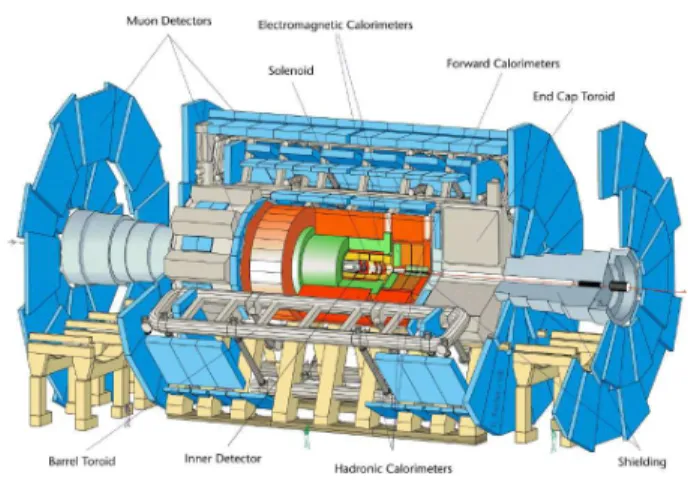
Fig. 1. Cut away view of the ATLAS detector. The muon spectrometer (blue) consists of a barrel part and two endcap regions. The detector measures 44 m in length and has a diameter of 22 m.
spectrometer has been designed to be capable of stand-alone operation (i.e. it does not require information from the inner detector or calorimeters to reconstruct muon tracks) with a resolution of better than 10% for muon momenta up to 1 TeV.
In the barrel part of the muon spectrometer three layers of MDT chambers are employed for tracking. Two layers are located at the inner and outer edge of the toroidal magnet, one layer inside the magnetic field. The chambers are arranged in projective towers with respect to the interaction point.
To achieve the desired momentum resolution with the three point sagitta measurement, each MDT chamber must reach a resolution of better than 50 µm—requiring a knowledge of the chamber geometry with an accuracy of 20 µm and including uncertainties of the chamber alignment across distances of up to 10 m. The trigger signal for the MDTs is provided by an independent system of fast—and therefore low occupancy—
trigger chambers (Resistive Plate Chambers) mounted on the middle and outermost MDT chamber layers.
Drift tubes are long, cylindrical, gas filled ionization detec-
tors with a single centered sense wire. The determination of
the impact radius of a charged particle within a tube is based
on the measurement of the drift time of the primary ionization
electrons to the anode wire with respect to an external trigger
signal; a so-called r(t)-relation is then used to convert drift
Longitudinal beam In−plane alignment
Multilayer Cross plate
Fig. 2. Schematic view of an ATLAS Barrel Monitored Drift Tube chamber.
time information to a radius prediction. In the case of MDT chambers this r(t)-relation can be determined by an iterative self-calibrating algorithm, the so-called auto-calibration [2].
ATLAS MDT chambers [1] consist of two multilayers, each built of 3 or 4 layers of densely packed drift tubes mounted on an aluminum support frame (compare fig. 2); the chamber sizes vary from about 1 m
2to 11 m
2while tube lengths range from 1 to 6 m. The individual drift tubes are also made of aluminum, have an outer diameter of 30 mm and a wall thickness of 400 µm. A goldplated W-Re anode wire with a diameter of 50 µm is stretched with a wire tension equivalent to 350 g in the center of the tube. The anode wire is fixed only at the tube ends using precision endplugs for centering; the sag of the wires in the tubes can be compensated by bending the chamber with respect to the support frame. The tubes are operated with an Ar/CO
2=93/7 gas mixture at 3 bar absolute pressure at a gas gain of 2 × 10
4(corresponding to a high voltage of 3080 V). An average single tube resolution of 80 µm can be achieved. The maximum drift time for electrons from hits near the tube wall to the anode wire is about 700 ns.
The geometry of the drift tube chamber is constantly mon- itored by optical alignment systems mounted in the support structure. These so-called RasNik [3] sensors consist of a backlit mask which is projected by a lens onto a CCD camera.
Analysis of the chessboard-like pattern of the mask image allows the determination of shifts of the sensor components perpendicular to the optical axis with a precision of 1 µm.
The MDT chambers also carry additional precision platforms on which optical components of the chamber-to-chamber align- ment monitoring system are mounted. During operation, the positions of the precision chambers and their deformations are constantly monitored to allow for misalignment corrections in the offline analysis.
The Max-Planck-Institut f¨ur Physik (MPI) and the Ludwig- Maximilians-University (LMU) at Munich have built 88 MDT chambers [4]–[6] for the outermost barrel layer of the ATLAS muon spectrometer. These so-called BOS (Barrel Outer Small) chambers are the second largest chamber type, most of them consisting of 432 drift tubes arranged in 2 × 3 layers and measuring 4 m × 2.2 m × 0.5 m and are mounted on the
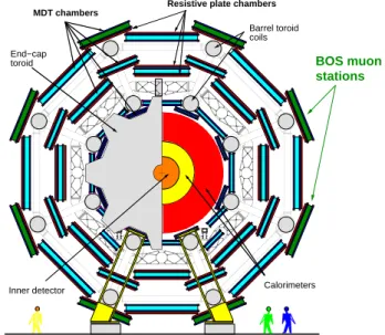
End−cap toroid
Barrel toroid coils
BOS muon stations
Calorimeters MDT chambers Resistive plate chambers
Inner detector
Fig. 3. Schematic cross section of the ATLAS detector.
outside of the toroid magnet coils (cp. fig. 3).
For detector control data, the BOS MDT chambers are equipped with 18 temperature sensors distributed on the mul- tilayers and the support structure, an inplane alignment mon- itoring system of 4 RasNik sensors and usually 4 precision platforms for the chamber-to-chamber alignment system along the detector axis; 32 chambers are equipped with 2 additional alignment platforms each, connecting these chambers to cham- bers in the next φ-sector.
The BOS MDT chambers are fully tested and commissioned at the production site [7]–[9] before being transported to CERN.
II. T
ESTS ANDI
NTEGRATION OFATLAS B
ARRELMDT C
HAMBERSUpon their arrival at CERN, the MDT chambers are subjected to a test programme—gas tightness, high voltage stability, tests of the read-out electronics and the optical and temperature sensors—to discover any damage which might have occurred during the transport from the production site and to ensure their proper operation in the experiment. The requirements to be fulfilled are defined in [10]. The MDT chambers of the middle and outer layer of the muon spectrometer are then mechanically integrated with their RPCs of the trigger system to single physical units, so-called muon stations, to simplify the installation in the detector. The completed muon station—
MDT, trigger chamber and Level 1 trigger electronics—is commissioned with cosmic rays. An overview on the test and integration procedures and a summary of the obtained results for the middle and outer muon stations is given in [11]. In this paper we focus on the test results for the BOS MDT chambers and their unique integration procedure.
The leak rate is determined for both multilayers separately
from the temperature corrected pressure drop over time. Due to
the short time interval (usually about 2 days) and the missing
temperature stabilization of the test area at CERN, the allowed
0 1 2 3 4 5 6 7 8
0 20 40 60 80
0 1 2 3 4 5 6 7 8
0 20 40 60 80
MDT Chamber
Leak Rate / (mbar/d)
Error: 2 mbar/d
0 0.02 0.04 0.06 0.08 0.1 0.12 0.14
0 20 40 60 80
0 0.02 0.04 0.06 0.08 0.1 0.12 0.14
0 20 40 60 80
MDT Chamber
Noise Rate / kHz
HV on HV off
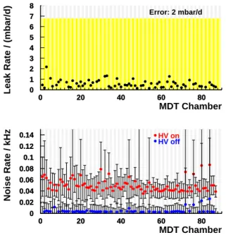
Fig. 4. Top: Mean leak rate of the two multilayers of BOS MDT chambers. The yellow area marks the allowed region. The measurement error is 2 mbar/day.
Bottom: Mean noise rate of BOS MDT chambers with (red) and without (blue) high voltage. The error bars denote the RMS of the distribution of the noise rate of the individual drift tubes. The allowed limit with applied high voltage is at 5 KHz.
leak rate for the BOS MDT chambers is 7 mbar/day, 10 times its nominal value. Fig 4 top summarizes the results for the 88 BOS MDT chambers. All chambers fulfill the requirements.
The high voltage stability at the nominal operating point is tested by measuring the dark current of each tube layer.
The noise rate is determined by randomly triggering the MDT chamber read-out electronics and scaling the number of hits by the inverse of the integral active time window of the data acquisition. The test is performed both without and with high voltage to allow a differentiation between electronic noise and discharges occurring inside the drift tubes (see fig. 4 bottom). At the same time the control interface of the front- end electronics is checked as well. All chambers fulfill the requirements of a maximum noise rate of 5 KHz for the individual tubes and 5 KHz for the mean value of all tubes.
After the initial tests the MDT chamber is equipped with B- field and chamber-to-chamber alignment sensors whose proper operation is then verified. Table I summarizes the failure rates of all components found at the production site and during the tests at CERN, which are below expectation in all areas.
The MDT chamber is then integrated with its RPC trigger chamber to form the muon station. The BOS muon stations require a special common support frame to carry the RPC and the MDT chamber (cp. fig 5) due to their position on the outside of the ATLAS toroid magnet coils. The RPC is inserted in the support frame and the MDT chamber is mounted on three kinematical bearings on top. The mechanical adjustment accuracy is 0.5 mm, fulfilling the requirements on the chamber
Category Total number Number of Number of Failure
of components Faults at Prod. Site Faults at CERN Rate / %
Leaky O-Ring Seals 289712 0 0 0
Disconnected Tubes 36192 18 1 0.05
Broken Wires 36192 11 3 0.04
Frontend-Elx Cards 4876 50 40 1.85
HV Splitter Boxes 88 0 3 3.41
DCS Boxes 88 0 4 4.55
T-Sensors 1584 2 3 0.32
Alignment-Sensor comp. 1056 0 3 0.28
B-Field Sensors 176 — 3 1.70
TABLE I
SUMMARY OF THE TOTAL NUMBER AND NUMBER OF FAULTY COMPONENTS OF THE88 BOS MDTCHAMBERS TESTED AT THE PRODUCTION SITE IN
MUNICH AND ATCERN.
Common Support Frame with RPC inside
Storage and Transport Feet x
y Drift Tube z
Layers
RPC Trigger Electronics Rail Bearings
MDT Chamber
Fig. 5. Schematic drawing of a BOS muon station.
alignment in the detector.
The completed muon station—which weights approx. 1 t—
is lifted into a rotator frame to check the adjustment under the angle at which it will be installed in the ATLAS detector. In the rotator, the MDT chamber is also bend to follow the wire sag of ± 74 µm or ± 179 µm, depending on the installation angle.
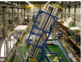
The precision and repeatability of the sag adjustment is better than 10 µm. Fig. 6 shows a photograph of a BOS muon station in the rotator frame at CERN.
A complete system test of the muon station is performed with cosmic muons. The drift time spectra and pulse height distributions for each tube of the MDT chamber are recorded and the chamber hit profile is measured to allow a check of the correct channel assignment. Similar tests ensure the proper operation of the RPC trigger chamber and the Level 1 trigger electronics.
The integration and certification of the 88 BOS MDT cham- bers lasted from August 2005 to February 2006. A maximum rate of 10 muon stations per week was reached. All MDT chambers successfully passed all acceptance tests.
III. I
NSTALLATION ANDC
OMMISSIONING OFM
UONS
TATIONS IN THEATLAS D
ETECTORAt the surface above the ATLAS cavern a series of tests
of gas pressure, high voltage stability, functionality and noise
rate of each electronics channel and of the alignment system
is performed on each muon station to ensure that no damage
Fig. 6. Photograph of an integrated BOS muon station in the rotator frame at the area at CERN (center). At the left side, BOS stations in various states of integration are visible, in the background the cosmic ray test stand.
Fig. 7. Installation of a BOS muon station in the ATLAS detector.
occurred during transport from the integration site. The me- chanical integrity of the station is checked as well. The muon station is then placed into an installation frame and lowered into the underground experimental hall. There, the installation frame is supported by two cranes, rotated to the appropriate angle and docked to the rail system of the ATLAS muon spectrometer, see fig. 7. The muon station is slid onto the rails with the help of two winches, positioned with an accuracy of 1 mm in all three spatial directions and fixed at one bearing on the rail. As an example, fig. 8 shows the positions of the 12 MDT chambers of one complete sector of the detector.
The final service lines—gas distribution, low and high voltage cables, detector control system cables and read-out fibers—are being routed and connected to the muon stations. Installation of the BOS muon stations began in mid February 2006 and was
-4 -2 0 2 4
0 2 4 6 8 10 12
-4 -2 0 2 4
0 2 4 6 8 10 12
MDT Chamber (z - znom) / mm
Fig. 8. Example of the deviation of the longitudinal MDT chamber positions from their nominal values for one sector of BOS MDT chambers. The yellow region marks the allowed range.
0 0.25 0.5 0.75 1 1.25 1.5 1.75 2
0 20 40 60 80
0 0.25 0.5 0.75 1 1.25 1.5 1.75 2
0 20 40 60 80
MDT Chamber
Leak rate / (mbar/d)
0 2 4 6 8 10 12
-60 -40 -20 0 20 40 60
Deviation of Sag Compensation / µm
Entries / 1 µm
Rms Mean
17.39 -14.64 Upper Sectors
Rms Mean
11.42 13.20 Lower Sectors Rms
Mean 3.01 0.21 Readj. on Rails
Fig. 9. Top: Mean leak rate of the two multilayers of BOS MDT chambers after installation in the ATLAS detector. The error is estimated by assuming a stable temperature within 1 K. The yellow region marks the allowed range. Bottom:
Deviation of the sag adjustment from its nominal value after installation of the BOS MDT chambers in the ATLAS detector. The green histogram shows the results for chambers of the upper detector sectors, which were transported in an upright position, the blue histogram the results for chambers of the lower sectors, which were transported in an inverted position. A mean shift of the order of 10µm is observed. The red histogram shows the results from chambers which could be readjusted on the rails.
completed by end of June 2006; a maximum rate of 4 stations per day was reached.
The commissioning of the MDT chambers starts immediately
after their installation: A check of the gas pressure and a high
voltage test are performed and the correct sag adjustment is
verified with the on-chamber alignment system. No gas leaks
or deviations of the chamber geometry have been observed after
installation. Fig. 9 summarizes the results of the long term leak
rate (top) and sag adjustment measurement (bottom).
IV. C
OMMISSIONING WITHC
OSMICR
AYM
UONSData taking with cosmic ray muons offers the possibility to fully commission the installed muon stations, the trigger system and the ATLAS data acquisition system prior to LHC collisions. A setup with 3 projective towers (i.e. three stations of each layer) and 4 BOS MDT stations in the adjacent sectors is foreseen to take data with and without magnetic field of the barrel toroid—which will be operated full field for the first time—in November 2006. The data will also provide valuable input for the calibration and the alignment of the muon spectrometer. Other sectors will be commissioned with cosmic rays after their final services have been connected.
V. C
ONCLUSIONSThe Max-Planck-Institut f¨ur Physik and the Ludwig- Maximilians-University in Munich have built 88 MDT cham- bers for the ATLAS barrel muon spectrometer. All MDT cham- bers passed the acceptance tests at CERN and were integrated with their RPC trigger chambers. The 88 muon stations were successfully installed and in the ATLAS experiment. After connection of the final services, the stations will be fully commissioned with cosmic rays.
VI. A
CKNOWLEDGMENTSWe would like to thank all people involved in the build- ing, commissioning, integration and installation of our cham- bers, especially S. Leber, T. Haubold, P. Klemm, M. Lippert, R. Sedlmeyer, A. Varga, H. Wetteskind, A. Wimmer, and J. Zimmer and our colleagues from the RPC community, CEA DSM/DAPNIA Saclay, and from CERN.
R
EFERENCES[1] ATLAS Muon Collaboration, ATLAS Muon Spectrometer Technical Design Report, CERN/LHCC/97-22, CERN, 1997
[2] G. Viehhauser, Detector Physics of the ATLAS MDT Muon Precision Chambers, PhD thesis, University of Vienna, 1996
M. Deile, Optimization and Calibration of the Drift-Tube Chambers for the ATLAS Muon Spectrometer, PhD thesis, Ludwig-Maximilians-Universit¨at Munich, 1998
[3] H. van der Graaf et al., RasNiK, an Alignment System for the ATLAS MDT Barrel Muon Chambers - Technical System Description, NIKHEF/ET38110 (2000)
[4] F. Bauer et al., Construction and test of MDT chambers for the ATLAS muon spectrometer, Nucl.Instrum.Meth. A461 (2001) 17–20
F. Bauer et al., Construction and test of the precision drift chambers for the ATLAS muon spectrometer, IEEE Trans.Nucl.Sci 48 (2001) 302–307 [5] S. Horvat, Study of the Higgs Discovery Potential in the Process
pp→H→4µ, PhD thesis, Zagreb University and Max-Planck-Institut f¨ur Physik (2005)
[6] S. Horvat et al., Final Evaluation of the Mechanical Precision of the ATLAS Muon Drift Tube Chambers, IEEE NSS 2006, Talk N32-1, San Diego, 2006 [7] O. Biebel et al., A Cosmic Ray Measurement Facility for ATLAS Muon
Chambers, e-Print physics/0307147 (2003)
[8] O. Biebel et al., Test and Calibration of Large Drift Tube Chambers with Cosmic Rays, IEEE Trans.Nucl.Sci 1 (2004) 221–225
[9] F. Rauscher, Untersuchung des Verhaltens von Driftrohren bei starken Gamma-Bestrahlung sowie Vermessung von Driftrohrkammern mit Hilfe von Myonen der kosmischen H¨ohenstrahlung, PhD thesis, Ludwig- Maximilians-Universit¨at Munich (2005)
[10] The Commissioning Working Group, MDT Commissioning Procedures Guidelines for Certifying RFI Chambers, ATL-MUON-2004-022, CERN, 2004
[11] A. Di Girolamo et al. Cosmic Ray Certification of the ATLAS Muon Barrel Chambers, IEEE NSS 2006, Talk N24-4, San Diego, 2006