On the Formal Semantics of Change Patterns in Process-aware Information Systems
Stefanie Rinderle-Ma1, Manfred Reichert1, and Barbara Weber2
1 Ulm University, Germany,{stefanie.rinderle, manfred.reichert@uni-ulm.de}
2University of Innsbruck, Austria, Barbara.Weber@uibk.ac.at
Abstract. Due to a turbulent market enterprises should be able to adapt their business processes in a quick and flexible way. This requires adaptive process-aware information systems (PAISs) which are able to support changes at different levels and of different process aspects. As for process modeling languages, a multitude of approaches, paradigms, and systems for realizing adaptive processes have emerged. This variety makes it difficult for PAIS engineers to choose the adequate technology.
Therefore we introduced a set of commonly used process change patterns which facilitate the comparison between different approaches and tools.
In this paper, we provide the formal semantics of these change patterns to ground pattern implementation and pattern-based analysis of PAISs on a solid basis. As challenge, we want to describe the formal seman- tics of change patterns independent of a certain process meta model.
Altogether, our formalization will enable unambiguous and systematic comparison of adaptive PAISs.
1 Introduction
For several reasons enterprises should provide flexible IT support for their busi- ness processes and be able to adapt them in a quick and flexible way. Process- aware information systems (PAISs) offer promising perspectives in this respect based on a strict separation of process logic and application code. The need for flexible and easily adaptable PAISs has been recognized for years and several competing paradigms for addressing process changes and flexibility have been developed (e.g., adaptive processes [1–3], case handling [4], declarative processes [5], and late modeling [1, 6]). Still, there is a lack of methods for systematically comparing the change frameworks provided by existing process support systems.
This, in turn, makes it difficult to assess the maturity and the change capabilities of those technologies, often resulting in wrong decisions and bad investments.
To make PAISs better comparable,workflow patternshave been introduced [7]. These patterns enable analyzing the expressiveness of process modeling tools and languages. Though workflow patterns enable building more flexible PAISs, an evaluation of a PAIS regarding its ability to deal with changes needs a broader view. In addition to the ability to pre-model flexible execution behavior based on advanced workflow patterns), run-time flexibility has to be considered [2]. The latter is addressed by exception handling patterns [8], which describe different
ways for coping with the exceptions that occur during process execution (e.g., activity failures). In many cases, changing the observable behavior of a running instance is not sufficient, but the process structure has to be adapted as well [9].
In addition, exception handling patterns cover changes at the process instance level, but are not applicable toprocess schema changes.
We extend existing workflow patterns by a set of patterns suitable for evaluat- ing the run-time flexibility of PAISs. In [10, 11] we have introduced 14change pat- terns. Extensive case studies have shown that these change patterns are common and frequently applied in different domains [12]. Examples include the patterns Insert, Move, and Replace. Further, we have evaluated different approaches and tools with respect to their support of the different change patterns. As for workflow patterns, however, it is crucial to provide aformal semanticsfor change patterns; i.e., for each change pattern its effects must be precisely defined. Other- wise, ambiguities in the semantics of a change pattern (e.g., whether an activity is inserted in a serial or parallel manner) will hamper both their implementation and the comparison of existing change frameworks. Workflow patterns have been defined based on techniques with inherent formal semantics (e.g., Petri Nets [7]
or Pi-Calculus [13]). However, such formalisms cannot be used to define change pattern semantics since we have to specify formal semantics of high-level change operations instead of workflow constructs. Further, since change patterns can be applied to different process meta models, their formal semantics should be described independent of a certain meta-model.
This paper provides a formal semantics for the change patterns presented in [10, 12] to ground their implementation as well as pattern-based analysis of PAISs on a solid basis. First, we classify change patterns based on their se- mantics. To stay independent of a certain process meta model, we base change pattern semantics on execution traces (trace for short) of processes. Further, we illustrate it by examples and explanations. Together with workflow patterns, change patterns with precise and formal semantics will push the breakthrough of flexible PAISs in practice. Sect. 2 provides background information. In Sect.
3 we recall the change patterns presented in [10, 11] and classify them based on their semantics. Sect. 4 provides the formal semantics for all 14 change patterns.
Sect. 5 discusses related work and Sect. 6 concludes with a summary.
2 Backgrounds
This section introduces basic notions needed and recalls change patterns as pre- sented in [10, 11].
2.1 Basic Notions
Generally, for each business process to be supported (e.g., order handling), a process type represented by a process schema has to be defined. For one par- ticular process type several process schemes may exist representing the different versionsandevolutionof this type over time. In the following, a process schema
corresponds to a directed graph, which comprises a set of nodes representing process steps (i.e., activities) or control connectors (e.g, XOR-Split, AND-Join), and a set of control edges between them. The latter specify precedence relations.
Activities can either beatomicorcomplex. While an atomic activity is associated with an invokable application service, a complex activity contains a reference to a sub process (schema). This enables the hierarchical decomposition of process schemes. Most of the patterns considered in this paper are not only applicable to atomic or complex activities, but also to sub process graphs with single entry and single exit node contained within the process schema (also denoted as ham- mocks [11]). In this paper, we use the term process fragment as a generalized concept covering atomic activities, complex activities (i.e., sub processes) and hammocks. If a pattern is denoted as being applicable to a process fragment, it can be applied to all these objects.
2.2 Process Changes and Adaptation Patterns
Changes of a process schemacan be applied at the process type as well as the pro- cess instance level [2]. Process changes at the type level often necessitate change propagation to already running process instances. Ad-hoc changes of single pro- cess instances, in turn, are performed to deal with exceptional situations during runtime. In particular, ad-hoc changes result in an adapted instance-specific pro- cess schema [3]. The effects of such ad-hoc changes are usually instance-specific, and consequently do not affect any other ongoing process instance.
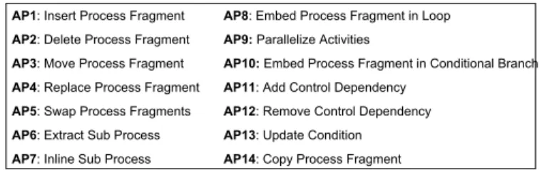
Change patterns(cf. Fig. 1) allow for the structural modification of a process schema at the type or instance level based on high-level change operations (e.g., to add an activity in parallel to another one). A high-level change operation, in turn, is based on a set of low-level change primitives (e.g., to add a single node or delete a single edge). Generally, change patterns can be applied to the whole process schema, i.e., the change region can be chosen dynamically. Therefore, change patterns are well suited for dealing with exceptions.
Design choicesenable the parametrization of change patterns by keeping the number of distinct patterns manageable. For example, whether an atomic activ- ity, a complex activity, or a hammock is deleted constitutes one design choice for the Delete Process Fragment pattern. Design choices which are not only relevant for a particular pattern, but for a set of patterns, are described only once for the entire pattern set. Typically, existing approaches only support a subset of the design choices in the context of a particular pattern. We denote the combination of design choices supported by a particular approach as a pattern variant. As discussed in [10, 14], general design choices valid for all change patterns are (A) the scope of the change pattern; i.e., whether it is possible to apply the
pattern at process type or process instance level
(B) the level of granularity the change pattern operates on:
atomic activity (1), sub process (2), and hammock (3).
In this paper, we abstract from design choices (A) and (B) since they do not affect the formal semantics of change patterns as defined by us. Regarding Design Choice (A), for example, change pattern AP2 (Delete Process Fragment)
AP1: Insert Process Fragment AP8: Embed Process Fragment in Loop AP2: Delete Process Fragment AP9: Parallelize Activities
AP3: Move Process Fragment AP10: Embed Process Fragment in Conditional Branch AP4: Replace Process Fragment AP11: Add Control Dependency
AP5: Swap Process Fragments AP12: Remove Control Dependency AP6: Extract Sub Process AP13: Update Condition AP7: Inline Sub Process AP14: Copy Process Fragment
Fig. 1.Adaptation Patterns Overview
could be implemented in a different way for the process type and the process instance level; e.g., replacing the activity to be deleted by a silent activity at the instance level, while physically deleting it at the type level. Furthermore, the applicability of change patterns at the instance level additionally depends on the state of the respective instances [2]. This, however, does not influence the formal semantics of pattern AP2 when defining it on basis of traces. Regarding Design Choice (B), we assume that sub processes as well as hammocks can be encapsulated within a complex activity. Then the formal semantics for applying change patterns to activities can be easily transferred to design choices B[2]
and B[3] as well. Thus, in this paper, the definition of formal pattern semantics refers to activities instead of process fragments. Exceptions are patterns AP6 (Extract Sub Process), AP7 (Inline Sub Process), and AP8 (Embed Process Fragment in Loop), since AP6 and AP7 are applied to sub processes and AP8 to process fragments respectively (Design Choice (B)). Pattern-specific design choices, however, influence the formal semantics of these patterns. Take the insert pattern AP1 applied to an atomic activity as an example. To be able to exactly decide on its semantics, it is necessary to specify whether the activity is inserted in a serial, parallel, or conditional manner; i.e., the semantics of this change pattern is determined by taking the respective design choice into account. Thus, we consider design choices when formalizing patterns.
3 Semantics-based Patterns Classification
To cluster formalization effects, we group change patterns according to their semantics; i.e., patterns with similar or related semantics (and therefore formal- ization) are summarized within one group.
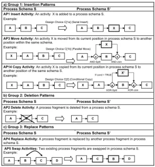
Group 1 (Insertion patterns):Our first group consists of change patterns AP1 (Insert Activity), AP3 (Move Activity), and AP14 (Copy Activity) (cf. Fig.
2a).These patterns are more or less based on the insertion of an activity at a certain position. How this position is determined constitutes pattern-specific design choice (C); i.e., the activity can be inserted serially (C[1a]), in parallel (C[1b]), or conditionally (C[2]). As example consider Fig. 2a. On the left side source schemes are depicted to which AP1, AP3, and AP14 are applied assuming
a particular design choice C. In this example a new activity is embedded between two single nodes. We generalize this later to activity sets as insertion patterns.
a) Group 1: Insertion Patterns
Process Schema S Process Schema S’
AP1 Insert Activity: An activity X is added to a process schema S.
Example:
AP3 Move Activity: An activity X is moved from its current position in process schema S to another position within the same schema.
Example:
AP14 Copy Activity: An activity X is copied from its current position in process schema S to another position of the same schema S.
Example:
b) Group 2: Deletion Patterns
Process Schema S Process Schema S’
AP2 Delete Activity: A process fragment is deleted from a process schema S.
Example:
c) Group 3: Replace Patterns
Process Schema S Process Schema S’
AP4 Replace Activity: A process fragment is replaced by another process fragment in process schema S.
AP5 Swap Activities: Two existing process fragments are swapped in process schema S.
Example:
A B C A B X C
Design Choice C[1a] (Serial Insert)
A B C
X
B X
C
A +
AND-Split + AND-Join Design Choice C[1b] (Parallel Move)
A B C
X
x XOR-Split
x XOR-Join B X’
C A
If cond = TRUE
X Design Choice C[2] (Conditional Copy)
A B C A C
B C D
A A C B D
Fig. 2.Insertion, Deletion, and Replace Patterns (Groups 1 to 3) – Examples
As can be seen from Fig. 2a, all patterns of Group 1 are based on the insertion of an activity. Obviously, this holds for AP1. For moving an activity (AP3), the respective activity is re-inserted after deleting it from its original position.
Finally, when copying an activity X, it remains at its original position and a copy of X (with new label1) is inserted.
Group 2 (Deletion patterns):This group only contains one change pat- tern since its formalization does not directly relate to any other pattern. Fig. 2b shows the deletion of an activity from a process schema.
Group 3 (Replace patterns): Within the third group, we subsume change patterns AP4 (Replace Activity) and AP5 (Swap Activities). As example, con- sider Fig. 2c. Here activities B and C are swapped in schema S; i.e., activity B is (logically) replaced by activity C and vice versa.
Group 4 (Embedding patterns): There are two change patterns AP8 (Embed Process Fragment in Loop) and AP10 (Embed Process Fragment in Conditional Branch) which form Group 4. Note that for both patterns a process fragment is embraced by a new construct (i.e., a loop or conditional branching, cf. Fig. 3a). By applying one of these patterns, the respective process fragment is either executed more often than before (AP8) or possibly not executed at all (AP10). Thus, a similar semantical description can be found for both patterns.
1 We claim unique labelling of activities.
a) Group 4: Embedding Patterns
Process Schema S Process Schema S’
AP8 Embed Process Fragment in Loop: Adds a loop construct to a process schema in order to surround an existing process fragment.
AP10 Embed Process Fragment in Conditional Branch: An existing process fragment shall be only executed if certain conditions are met.
Example:
b) Group 5: Order Changing Patterns
Process Schema S Process Schema S’
AP9 Parallelize Activities: Activities which have been confined to be executed in sequence so far are parallelized in a process schema S.
Example:
AP11 Add Control Dependency: An additional control edge (e.g., for synchronizing the execution order of two parallel activities) is added to process schema S.
AP12 Remove Control Dependency: A control edge is removed from process schema S.
AP13 Update Condition: A transition condition in the process schema is updated.
Example:
c) Group 6: Hierarchy Changing Patterns
Process Schema S Process Schema S’
AP6 Extract Sub Process: From a given process schema S a process fragment is extracted and replaced by a corresponding sub process.
Example:
AP7 Inline Sub Process: A sub process to which one or more process schemes refer is dissolved.
Accompanying to this the corresponding sub process graph is directly embedded in the parent schemes.
A B C D x
XOR-Split
x XOR-Join
C D
B condition
A
C D E
B
A C
B
E
A +
AND-Split
+ AND-Join D
x XOR-Split
x XOR-Join B X
C A
d < 50000
x XOR-Split
x XOR-Join B X
C A
d < 10000
C D E
B
A A P C
C D
B
Fig. 3.Embedding, Order and Hierarchy Changing Patterns (Groups 4 to 6)
Group 5 (Order Changing / Update Patterns)comprises all patterns which either change the order of activities within a process schema or update transition conditions. As example, consider AP9 (Parallelize Activities) as de- picted in Fig. 3b. AP9 changes the execution order for a selected set of activities, which are ordered in sequence before and parallelizes them within new schema S’; i.e., execution order of these activities is relaxed within the new schema. The same is achieved by removing control dependencies (AP12). Opposed to this, AP11 (Add Control Dependency) tightens the execution order of activities; e.g., two activities ordered in parallel before are executed in sequence when adding a control edge between them. Finally, AP13 (Update Condition) enables the modi- fication of transition conditions. In Fig. 3b, for example, the transition condition of a particular branch is updated to ”d<10000” based on AP13.
Group 6 (Hierarchy Changing Patterns)comprises patterns which add or remove levels from a process schema and thus change its hierarchical structure.
Pattern AP6 (Extract Sub Process) adds levels to a schema by extracting a selected sub process from schema S and nesting it ”under” a new complex activity P (cf. Fig. 3c). AP7 (Inline Sub Process) is the counter operation of AP6. It
removes levels from the process hierarchy by dissolving complex activities and inlining the associated sub process schema into S.
4 Formalization of Adaptation Patterns
4.1 Basic Notions
First of all, we introduce basic notions needed for the following considerations. In workflow literature, for example, the formal description of control flow patterns has been based on Petri Nets [7] or Pi-Calculus [13]. Therefore these patterns have an inherent formal semantics. Regarding change patterns, we aim at a for- mal description independent of a particular process meta model. To achieve this, we base the formal description of change patterns on the behavioral semantics of the process schema before and after its change. One way to capture behavioral semantics is to use traces [15].
Definition 1 (Trace). LetPS be the set of all process schemes and let Abe the total set of activities (or more precisely activity labels) based on which process schemes S∈ PS are specified (without loss of generality we assume unique labeling of activities in the given context). Let further QS denote the set of all possible traces producible on process schema S ∈ PS. A particular trace σ ∈ QS is then defined as σ = <
a1, . . . , ak>(withai ∈ A, i= 1, . . . , k, k ∈ N) where the temporal order ofai inσ reflects the order in which activitiesai were completed over S2.
Furthermore, we define the following two functions:
– tracePred(S, a, σ)is a function which returns all activities within process schema S completed before the first occurence of activity a within traceσ. Formally: tracePred:
S × A × QS →2A with
traceP red(S, a, σ) =
⎧⎪
⎪⎨
⎪⎪
⎩
∅ if a∈ {σ(i) |i ≤ |σ|}
(σ(i)denotes the ithitem in σ, cf. T ab.1) {a1, . . . , ak}if σ=< a1, . . . , ak, a, ak+1, . . . , an>
∧aj = a ∀j= 1, ..., k
– Analogously, traceSucc(S, a, σ)denotes a function which returns all activities within process schema S completed after the last occurence of activity a in traceσ. For- mally: traceSucc:S × A × QS →2A with
traceSucc(S, a, σ) =
⎧⎨
⎩
∅ if a∈ {σ(i)|i ≤ |σ|}
{ak+1, . . . , an}if σ=< a1, . . . , ak, a, ak+1, . . . , an>
∧aj = a∀j=k+ 1, ..., n
Function tracePred (traceSucc) determines the predecessors (successors) of the first (last) occurence of a certain activity within a trace; i.e., those activities which precede (succeed) the considered activity due to a loop back are not taken into account. Fig. 4 shows a schema with two loops, an example of a
E
D F
C A B
ı = <A1, B1,C1, D1, B2, C2, D2,E1, C3, D3, B3, C4, D4, E2,C5, D5,E2, F1>
tracePred(C ,ı) = {A, B}; traceSucc(C ,ı) = {D , E, F}
Xn: nth occurence of X in ı tracePred(E,ı) = {A, B, C , D }; traceSucc(E,ı) = {F}
Fig. 4.Functions tracePred and traceSucc applied to trace
corresponding trace, and the sets resulting from the application of tracePred andtraceSuccin different context.
In addition to Def. 1, Table 1 contains useful notions which facilitate the formalization of the change patterns.
Letσ =< a1, . . . , an>∈ QS be a trace on process schema S. Then:
|σ|: cardinality ofσ
σ(i) = ai: ithitem in trace σ x ∈ σ⇐⇒ ∃i≤ |σ|withσ(i) = x B⊆ σ ⇐⇒ ∀b ∈ B: b∈ σ
σX−→discard all items fromσwhich belong to set X Example:σ−{a1,an}=< a2, . . . , an−1>
σX+ →discard all items fromσnot belonging to set X example:σ{a+1,an}=< a1, an>
Table 1.Useful notions based on Def. 1
4.2 Adaptation Pattern Semantics
Based on the meta model independent notions of Def. 1 and Tab. 1 we now describe formal semantics of the different change patterns introduced in Sect. 3 (cf. Fig. 2+3). The given formal specifications do not contain any constraints specific to a particular meta model. This has to be achieved separately by as- sociating change operations with meta model-specific pre-/post-conditions. Our specifications contain generally valid pre-conditions where necessary; e.g., a node can only be deleted if it is present in the original schema. The post-conditions specify the effects of applying the respective change pattern (i.e., its semantics).
Insertion Patterns (Group 1) The fundamental pattern of this group is AP1 (Insert Activity) since patterns AP3 (Move Activity) and AP14 (Copy Activity) are based on the insertion of an activity as well (cf. Fig. 2). Thus, we first present formal semantics for AP1. When formalizing the semantics of a change pattern we first specify necessary preconditions for its application. Then we describe the effects resulting from its application. To stay independent of a particular meta model, the latter is accomplished based on traces; i.e., we describe the relation between traces producible on original schema and modified schema.
2 A particular activity can occur multiple times within a trace due to loopbacks.
Pattern Semantics 1 (Insert Activity, AP1) AP1 corresponds to high-level operation op = Insert(S, x, A, B) → S’ where S and S’ denote process schemes be- fore and after change. Further A and B denote activity sets between which activity x shall be inserted. Then the semantics of AP1 is given as follows:
(1) S does not contain a node with label x. Further, S contains activity sets A and B.
(2) ∀μ ∈ QS:∃σ ∈ QS withμ−{x} = σ and vice versa
(3) Considered design choices: Serial Insert (C[1]) and Parallel Insert (C[2]):
∀μ ∈ QS with A⊆μ(i.e., all nodes of A contained inμ):
{μ+A∪B∪{x}(i)|i = ν, . . . , ν+|A| −1}= A forν ∈ N
=⇒
μ+A∪B∪{x}(ν+|A|) = x∧
{μ+A∪B∪{x}(i)|i = ν+|A|+ 1, . . . , ν+|A|+|B|}= B
(1) formalizes generic pre-conditions for inserting an activity in schema S;
e.g., the activity to be inserted must not yet be present in S. (2) defines the relation between traces on S and new schema S’. For each trace σ on S there exists a corresponding trace μ on S’ for which μ−{x} = σ holds; i.e., when discarding newly inserted activity x from μ, this trace equalsσand vice versa.
This expresses the close relation between traces producible on S and S’. It further indicates that traces on S’ may additionally contain x whereas those on S do not.
Concerning AP1, we distinguish three design choices: Serial Insert (C[1a]), Parallel Insert (C[1b]), and Conditional Insert (C[2]) (see Fig. 2). Regarding design choices C[1a] and C[1b] the following conditions for newly inserted activity x in tracesμon S’ hold (cf.Pattern Semantics 1): If all nodes of predecessor set A are contained in traceμon S’, then the entries of x and B will be present inμ as well. When projectingμonto the entries of activity setA ∪ B ∪ {x} (i.e., μ+A∪B ∪ {x}), the entry of x is positioned directly after all entries of A and the entries of B directly succeed the entry of x within the respective trace. Note that the last condition (3) has to be modified in case of a conditional insert, since the presence of entries of A inμon S’ does not imply the presence of x.
Pattern Semantics 2 (Insert Activity, AP1 - Conditional Insert) Let the preconditions be as in Pattern Semantics 1. Then
(3’) Considered design choice: Conditional Insert (C[2]):
∀μ ∈ QS with x ∈μ: μ+A∪B∪{x}(ν+|A|) = x
=⇒
{μ+A∪B∪{x}(i)|i = ν, . . . , ν+|A| −1}= A∧
{μ+A∪B∪{x}(i)|i = ν+|A|+ 1, . . . , ν+|A|+|B|}= B
Condition (3’) implies that if x is present inμon S’ the entries of predecessor set A and successor set B will be contained inμon S’ as well. Furthermore, in the projection ofμonto the entries of activity setA ∪B ∪ {x}(i.e.,μ+A∪B∪ {x}), the entries of A directly precede x and the entries of B directly succeed x.
Similarly, formal semantics for AP3 (Move Activity) can be defined. Condi- tions (3) and (3’) which describe the position of x in μ(on S’) are equal to the ones of AP1. However, there is a different pre-condition for AP3 (Move Activity):
x must be present in S in order to be moved afterwards. The relation between traces on S and S’ is also different from AP1 (Insert Activity). Formally:
∀σ ∈ QS:∃μ ∈ QS withσ{x}− = μ−{x}and vice versa
Traces on S as well as traces on S’ might contain x but at different positions.
Therefore we claim that the projections of these traces (i.e., the traces where x will be discarded if present) have to be equal. Note that this reflects well the semantics of the Move change pattern.
Finally, AP14 (Copy Activity) is related to AP1 (Insert Activity) as well.
Again the position of copied (and re-labelled) activity x’ can be formalized by conditions (3) and (3’) as for AP1 (Insert Activity). Similar to AP3 (Move Activity) the activity to be copied must be present in S (1). Additionally, labels of the activity to be copied and the copied activity itself must be different from each other and no activity with the new label must be already contained in S.
Copying an activity x (with new label x’) can be seen as inserting x’ at the respective position. Therefore, the relation between traces on S and S’ can be defined as for AP1, but based on x’; i.e., when discarding copied activity x’ from μ(on S’), there exists an equal traceσon S. Formally3:
∀μ ∈ QS:∃σ ∈ QS withμ−{x} = σand vice versa
Deletion Patterns (Group 2) The semantics of AP2 (cf. Fig. 2) comprises preconditions and statements on the relation between traces on S and S’:
Pattern Semantics 3 (Delete Activity, AP2) AP2 corresponds to high-level operation op = Delete(S, x)→ S’ where S and S’ denote process schemes before and after its adaptation and x denotes the activity to be deleted. The semantics of AP2 is given as follows:
(1) Process schema S contains a node with label x.
(2)∀μ ∈ QS: x∈ μ
(3)∀μ ∈ QS:∃σ ∈ QS withμ = σ{x}− ∧
∀σ ∈ QS:∃μ ∈ QS withσ{x}− = μ
When deleting activity x, first of all, the process schema has to contain a node with label x. As an effect resulting from the application of AP2, all traces μ on S’ must not contain x. Finally, for all projections of σ on S where x is discarded fromσwe can find an equal trace on S’ and vice versa.
Replace Patterns (Group 3) We illustrate AP5 (Swap Activities, cf. Fig.
2) since it ”contains” the formalization for AP4 (Replace Activity). Note that swapping x and y can be (logically) seen as replacing x by y and y by x.
Pattern Semantics 4 (Swap Activities, AP5) AP5 corresponds to high-level operation op= Swap(S, x, y)→S’ where S and S’ denote process schemes before and
3 A complete formalization of AP3 and AP14 can be found in a technical report [11].
after the adaptation. Further x and y denote the activities to be swapped. The semantics of AP5 is given as follows:
(1) Process schema S contains one node with label x and one with label y.
(2)∀σ ∈ QS:∃μ ∈ QS with|σ| = |μ| ∧
μ(i) =
⎧⎨
⎩
σ(i)if σ(i) ∈ {x, y}
x if σ(i) = y y if σ(i) =x and vice versa
Alternatively we can formulate (2) as follows:
(2’)∀σ ∈ QS:
∃μ ∈ QS: with|σ| = |μ| ∧ σ{x,y}− = μ−{x,y} ∧(σ(k) = x=⇒μ(k) = y) and vice versa
To be swapped, activities x and y must be both contained in schema S (1).
The relation between traceσon S and corresponding traceμon S’ can be formal- ized in two ways. In both cases, for all tracesσon S, there exists a corresponding traceμon S’ for which the cardinalities ofσandμare equal. Regarding the po- sitions of swapped activities x and y, we can explicitly state that for all tracesσ on S, a traceμon S’ can be found such that all entries ofμare equal to entries of σ except at positions of x and y where the entries are swapped; i.e., at the position of x in σ, μcontains y and vice versa (2). Alternatively, for all traces σon S there exists a corresponding traceμon S’ for which the projections ofσ andμ resulting from discarding x and y are equal (2’). Further,μcontains the entry of y at the position of x inσand vice versa.
Embedding Patterns (Group 4) Formalization of pattern AP8 (Embed Pro- cess Fragment in Loop, cf. Fig. 3) is as follows:
Pattern Semantics 5 (Embed Process Fragment in Loop, AP8) AP8 cor- responds to high-level operationop= Embed in Loop(S, P, cond)→S’ where S and S’
denote process schemes before and after its adaptation. Further P denotes the set of activities to be embedded into a loop and cond denotes the loop backward condition.
Then the semantics of AP8 is given as follows:
(1) The sub graph on S induced by P has to be connected and must be a hammock, i.e., have single entry and single exit node.
(2) QS ⊂ QS
(3) ∀μ ∈ QS: Letμ be the trace produced by discarding all entries of
activities in P (if existing) fromμexcept the entries of one arbitrary loop iteration over P. Thenμ ∈ QS holds.
As a first characteristics, we formalize the relation betweenQS andQS. If the number of loop iterations is finite (i.e., the set of traces on a process schema containing loops is finite as well),QS ⊂ QS holds (1). Reason is that for all tracesσon S, a traceμon S’ can be found withσ = μbut not vice versa (due to the possibly iterative execution of the new loop).
To find a more specific characterization of the relation betweenQS andQS, for all traces μ on S’ trace projection μ is constructed as follows: All entries
of activities from P (if existing) are discarded from μexcept the entries of one arbitrary loop iteration; i.e.,μ is projected onto a ”loop-free” version of itself.
Obviously, the resulting traceμ is a trace on S as well (i.e.,μ ∈ QS).
For pattern AP10 (Embed Process Fragment in Conditional Branch), first of all, precondition (1) for AP8 must hold as well (cf. Pattern Semantics 5).
Further, QS ⊆ QS holds. Due to the newly inserted conditional branch only a subset of traces might be generated on S’ when compared to S. Finally, the relation between traces on S and traces on S’ can be defined more precisely; i.e., for all tracesσon S, if we discard all entries of P fromσ, the resulting projection is contained in the set of traces on S’. Formally:
∀σ ∈ QS:σP− ∈ QS (if cond = FALSE is possible)
Order Changing / Updating Patterns (Group 5) This group comprises change patterns which change the execution order between activities or update transition conditions (cf. Fig. 3). We describe AP9 (Parallelize Activities), since AP12 (Remove Control Dependency) can be seen as special case of AP9. AP11 (Add Control Dependency) is the reverse operation to AP12. AP13 (Update Condition) is explained afterwards.
Pattern Semantics 6 (Parallelize Activities, AP9) AP9 corresponds to high- level operation op = Parallelize(S, P) → S’ where S and S’ denote process schemes before and after its adaptation. Further P denotes the set of activities to be parallelized.
Then the semantics of AP9 is given as follows:
(1) Within schema S, the sub graph induced by P constitutes a sequence with single entry and single exit node.
(2)∀σ ∈ QS:∃μ ∈ QS withσ=μ(i.e.,QS ⊂ QS) (3)∀p, p ∈ P:∃μ1, μ2 ∈ QS with
(p∈tracePred(S’, p,μ1)∧p ∈tracePred(S’, p,μ2)) (assuming that the sequence defined by P can be enabled in S)
As a prerequisite of AP9, all activities to be parallelized must be ordered in sequence (1). As a basic characterization of AP9, the set of traces on S is a subset of the set of traces on S’ (2) since traces on S’ might contain entries reflecting a sequential order of P, too, but also any other execution order regarding activities from P (3). More precisely, every pair of activities contained in traceμon S’ is ordered in parallel in the new schema.
Regarding AP12 (Remove Ctrl Dependency), the formal semantics of AP9 is applied to exactly two activities. For AP11 (Add Control Dependency), the conditions of AP12 hold in reverse direction, i.e., execution order is made stricter on S’ such thatQS becomes a subset ofQS.
A different semantics has to be defined for AP13 (Update Condition):
Pattern Semantics 7 (Update Condition, AP13) AP13 corresponds to high- level operation op = Update Ctrl Dependeny(S, x, y, newCond)→ S’ denote process
schemes before and after its adaptation. Further oldCond (newCond) denotes the (tran- sition) condition of control edge x→y in S’ before (after) update. The semantics of AP13 is given as follows:
(1) oldCond=⇒newCond:∀μ ∈ QS for which transition condition newCond evaluates to TRUE:∃σ ∈ QS withμ = σ
(2) newCond =⇒oldCond:∀σ ∈ QS for which transition condition oldCond evaluates to TRUE:∃μ ∈ QS withμ = σ
(3) Otherwise, for all traces σ ∈ QS there exists a traceμ ∈ QS for which the following holds: If we produce projections forσandμby discarding all entries belonging to the conditional branch with updated condition, these projections are equal.
More precisely, we can derive a statement about the relation of traces between S and S’ if we know the relation between old and updated condition ((1) or (2)).
The projections ofσandμas described in (3) can be easily accomplished based on, for example, block-structured process meta models.
Process Hierarchy Changing Patterns (Group 6) AP6 (Extract Sub Process) and AP7 (Inline Sub Process) are counterparts of each other (cf. Fig.
3). We illustrate AP6, the formal semantics of AP7 can be directly concluded.
When formalizing AP6 a challenge is to specify the relation between tracesμon S’ and traces σ on S. Note that the entries of P inμ might have to be inlined
”instead of” the entry of x inσ. This becomes even more difficult in connection with loops since x is possibly executed multiple times.
Pattern Semantics 8 (Extract Sub Process (AP6)) AP6 corresponds to high-level operationop= Extract(S, P, x)→S’ where S and S’ denote process schemes before and after its adaptation. Further P denotes the set of activities to be extracted and x denotes the label of the abstract activity which substitutes the sub graph induced by P (and refers to a corresponding sub process schema) on S’. Then the semantics of AP6 is given as follows:
(1) The sub graph on S induced by P has to be connected and must be a hammock, i.e., have single entry and single exit node.
(2) ∀σ ∈ QS:∃μ ∈ QS withμ−{x} = σP− ∧
∀μ ∈ QS:∃σ ∈ QS:σ−P = μ−{x}
(3) Let z denote the single exit node of the sub graph induced by P.
Then:∀σ ∈ QS withσP−\{z}(k) = z: ∃μ ∈ QS withμ(k) = x (4) LetP denote the set of all traces over the sub graph induced by P and
let furtherπ ∈ P. Then:
∀ μ ∈ QS with μ(νi) = x (i = 1, . . . , n, νi ∈ N): ∃ σ ∈ QS with
σ(k) =
⎧⎪
⎪⎨
⎪⎪
⎩
=μ(k) k= 1, . . . , ν1−1,
=μ(k−j∗ |π|+j) k=νj+|π|, . . . , νj+1−1∧ k=νn+|π|, . . . ,|μ|+n∗(|π| −1)
=π(l) k=νi+l−1 where j = 1,. . ., n-1; l = 1,. . . , |π|
The relation between traces on S and on S’ can be formalized as follows: For all tracesσon S we can find a traceμon S’ for which the projections resulting
from discarding all entries of sub process P fromσand discarding the entry of x from μare equal (1). The interesting question is how to determine the position of x on S’ when extracting P from S. For this, we build a projection of traceσ on S by discarding all entries of activities in P except the one of single exit entry z (2). Then we can find a trace μon S’ for which the position of z within the projection ofσdetermines the position of x inμ. The other direction (i.e., how to determine the positions of activities in P on S), which is also important in the context of AP7 (Inline Sub Process), is more challenging. We solve this by constructing a traceσon S for allμon S’. First the position(s) of x inμis (are) determined (ν1, ..., νn). In the context of loops, this might be more than one position. Then the activities of P are inserted at this (these) position(s) within σ (3). The remaining part ofσcan be constructed using the entries ofμ, only the positions have to be shifted accordingly.
5 Related Work
Flexibility in PAISs has been addressed in different ways including declarative approaches [6], case-handling [4], and process changes at different levels [2, 3, 9]. Some approaches have additionally addressed instance-specific change and type-level change within one system [2]. All this work shows how crucial it is to provide sufficient solutions for flexible PAISs for applying them in practice.
However, there is no common understanding of change operations or change patterns in all of these approaches such that for users it might be difficult to compare them with respect to their particular needs.
The general idea of using patterns to compare PAISs has been proposed by the workflow patterns project [7]. Based on respective patterns, the expressive- ness of different process meta models and thus tools can be compared. Further patterns have been presented including data flow patterns [16], resource patterns [17], exception handling patterns [8], and service interaction patterns [18]. Most of them come along with a formal semantics, for example, based on languages such as Petri Nets [7] or Pi-Calculus [13].
For the first time, change patterns have been (informally) introduced in [10, 11] and evaluated in [12]. However, no formal semantics of change patterns has been provided so far, even though this is crucial for implementing and comparing PAISs. This paper closes this gap.
6 Summary and Outlook
We have specified the formal semantics for process change patterns [10, 11]. This provides the basis for implementing the patterns in PAISs as well as for com- paring PAISs with respect to flexibility since ambiguities are discarded. We first classified the change patterns along similar semantics to facilitate the specifica- tion of their semantics. For each pattern its formal semantics has been specified based on traces to stay independent of a particular process meta model. Cur- rently, we are formalizing the semantics of pre-defined change patterns [10, 11]
as well. Such patterns include, for example, theLate Selection of Process Frag- ments or the Late Modeling of Process Fragments. Our future work includes change patterns for aspects other than control flow (e.g., data or resources) and patterns for advanced change scenarios (e.g., adapting data flow when changing control flow). Further, we will provide a reference implementation and use the patterns for process refactoring [19].
References
1. Adams, M., ter Hofstede, A., Edmond, D., van der Aalst, W.: A Service-Oriented Implementation of Dynamic Flexibility in Workflows. In: Proc. Coopis’06. (2006) 2. Rinderle, S., Reichert, M., Dadam, P.: Flexible support of team processes by adaptive workflow systems. Distributed and Parallel Databases16(2004) 91–116 3. Reichert, M., Dadam, P.: ADEPTflex – Supporting Dynamic Changes of Work-
flows Without Losing Control. JIIS10(1998) 93–129
4. Van der Aalst, W., Weske, M., Gr¨unbauer, D.: Case handling: A new paradigm for business process support. Data and Knowledge Engineering. 53(2005) 129–162 5. Pesic, M., Schonenberg, M., Sidorova, N., , van der Aalst, W.: Constraint-Based
Workflow Models: Change Made Easy. In: CoopIS’07. (2007) 77–94
6. Sadiq, S., Sadiq, W., Orlowska, M.: A Framework for Constraint Specification and Validation in Flexible Workflows. Information Systems30(2005) 349 – 378 7. Van der Aalst, W., ter Hofstede, A., Kiepuszewski, B., Barros, A.: Workflow
Patterns. Distributed and Parallel Databases14(2003) 5–51
8. Russell, N., van der Aalst, W., ter Hofstede, A.: Exception Handling Patterns in Process-Aware Information Systems. In: Proc. CAiSE’06. (2006) 288–302 9. Rinderle, S., Reichert, M., Dadam, P.: Correctness Criteria for Dynamic Changes
in Workflow Systems – A Survey. Data and Knowledge Engineering 50 (2004) 9–34
10. Weber, B., Rinderle, S., Reichert, M.: Change patterns and change support features in process-aware information systems. In: Proc. CAiSE’07. (2007) 574–588 11. Weber, B., Rinderle, S., Reichert, M.: Change Support in Process-Aware Informa-
tion Systems - A Pattern-Based Analysis. Technical report, CTIT (2007)
12. Weber, B., Reichert, M., Rinderle-Ma, S.: Change patterns and change support features - enhancing flexibility in process-aware information systems. Data and Knowledge Engineering (2008)
13. Puhlmann, F., Weske, M.: Using the Pi-Calculus for Formalizing Workflow Pat- terns. In: Proc. BPM’05. (2005) 153–168
14. Zhang, F., D’Hollander, E.: Using Hammock Graphs to Structure Programs. IEEE Transactions on Software Engineering 30(2004) 231–245
15. V. Glabbeek, R., Goltz, U.: Refinement of actions and equivalence notions for concurrent systems. Acta Informatica 37(2001) 229–327
16. Russell, N., ter Hofstede, A., Edmond, D., van der Aalst, W.: Workflow data patterns. Technical Report FIT-TR-2004-01, Queensland Univ. of Techn. (2004) 17. Russell, N., ter Hofstede, A., Edmond, D., van der Aalst, W.: Workflow resource
patterns. Technical Report WP 127, Eindhoven Univ. of Technology (2004) 18. Barros, A., Dumas, M., ter Hofstede, A.: Service Interaction Patterns. In: Proc.
BPM’05. (2005) 302–318
19. Weber, B., Reichert, M.: Refactoring process models in large process reposito- ries. In: Proc. 20th Int’l Conf. on Advanced Information Systems Engineering (CAiSE’08). (2008) 124–139