Requirements Eng
DOI 10.1007/s00766-012-0162-3
Time Patterns for Process-aware Information Systems
Andreas Lanz · Barbara Weber · Manfred Reichert
Received: 29 December 2011 / Accepted: 28 July 2012
Abstract Companies increasingly adopt process-aware information systems (PAISs) due to their promising perspectives for improved business process support. Al- though the proper handling of temporal constraints is crucial in this context, existing PAISs vary significantly regarding their support of the temporal perspective of a business process. To make PAISs comparable in re- spect to their ability to deal with temporal constraints and to facilitate the development of a time-aware PAIS, this paper suggests 10 time patterns. All patterns are based on empirical evidence we gathered in case studies.
Additionally, they are validated through a systematic literature review. Based on the time patterns, we then provide an in-depth evaluation of selected PAISs and academic approaches. Altogether, the 10 time patterns will not only facilitate the selection of technologies for realizing time- and process-aware information systems, but can also be used as reference for implementing time support in PAISs.
Keywords Process-aware Information System, Work- flow Patterns, Time Patterns, Temporal Perspective
Andreas Lanz
Univ. of Ulm, Institute of Databases and Information Systems James-Frank-Ring, 89069 Ulm, Germany
E-mail: andreas.lanz@uni-ulm.de Barbara Weber
University of Innsbruck, Department of Computer Science Technikerstraße 21a, 6020 Innsbruck, Austria
E-mail: barbara.weber@uibk.ac.at Manfred Reichert
Univ. of Ulm, Institute of Databases and Information Systems James-Frank-Ring, 89069 Ulm, Germany
E-mail: manfred.reichert@uni-ulm.de
1 Introduction
Today’s enterprises crave for comprehensive knowledge about and control over their business processes. In par- ticular, a profound understanding and control of these processes can lead to competitive advantages. In this context, process-aware information systems (PAISs) of- fer promising perspectives by enabling enterprises to define their business processes based on explicit process models as well as to execute these models in a controlled and efficient manner [69, 52].
The specification of a business process can be viewed from different perspectives [2, 26, 52]. Thecontrol-flow perspective describes the activities of a business pro- cess as well as their ordering and execution constraints.
In turn, the data perspective connects activities with business and process data. Furthermore, he resource perspectiveprovides a link between the process specifi- cation and the organizational structure, e.g., based on user roles assigned to process activities [54]. Finally, the operational perspectiverefers to the application services executed in the context of activities. However, another important perspective required for the broad acceptance and use of PAISs has received too little attention so far, namely thetemporal perspective. Although there exists considerable work related to specific aspects of time in PAIS, so far, there has been no comprehensive frame- work considering the temporal perspective as a whole.
In today’s fast paced world, where even small delays can cause significant problems, it is crucial for any enterprise to know the temporal properties of its business processes [15, 41, 22, 20]. This becomes even more important in the context of long-running business processes like patient treatment or automotive engineering [20, 42].
2 Andreas Lanz et al.
1.1 Problem Statement
Both the formal specification and the operational sup- port of temporal constraints constitute fundamental challenges for any PAIS. So far, however, time support has been rather limited in existing PAISs and there is a lack of criteria for systematically assessing and compar- ing the time capabilities provided by PAISs. To make PAISs better comparable and to facilitate the selection of PAIS-enabling technologies in a given context, workflow patterns have been introduced for most of the described process perspectives [3, 59, 58, 67]. Respective patterns provide a means for analyzing the expressiveness of pro- cess modeling languages and tools regarding different process perspectives. Additionally, patterns can be used for eliciting and analyzing requirements described by for- mal process specifications. Existing workflows patterns, for example, cover control flow [3], data flow [59], re- sources [58], activities [66], exceptions [57], and process change [67, 55]. However, a framework for systematically evaluating process specifications in respect to their re- quirements concerning the temporal perspective as well as for evaluating PAISs in respect to their ability to deal with the temporal perspective is still missing. To discuss some of the challenges being relevant in this context we first introduce a simple example:
Example 1 (Patient Treatment Process) Consider the simplified patient treatment process depicted in Fig. 1.
First, a doctor orders a medical procedure for his patient.
Then, the responsible nurse makes an appointment with the department (e.g., radiology) the procedure will take place. Before the actual treatment, the patient needs to be informed about the procedure and prepared for it.
Shortly before the treatment starts, a specific prepara- tion is required. After the treatment, the doctor writes a short report if requested. Finally, aftercare is provided and the doctor creates a final medical report, which is then added to the patient record.
When considering the temporal perspective of this rather simple process, a number of constraints can be observed:
1. The appointment of thetreatment, which is made during activitymake appointment, needs to be ob- served during process execution. In particular, this affects the scheduling of preceding activities as well.
For example, the patient needs to be preparedexactly 1 day before actual treatmenttakes place. Hence, the preparation needs to be scheduled in accor- dance with theappointment of thetreatment.
2. The preparationof the patient may only be done during opening hours of the anesthesia department, i.e., fromMonday till Friday between 8am and 4pm.
This further restricts possible execution times of activity prepare patient and hence the ones of thetreatmentitself.
3. Due to a tight schedule of the treatment room,prep- arationof the treatment mustnot take more than 1 hour; otherwise,treatmentis delayed.
4. During the execution of activityperform aftercare, different drugs are given to the patient according to the treatment plan defined by activity perform treatment. Such a treatment plan may state, for example, that drug A has to be administered every day at 8 am, 1 pm, and 6 pm, and drug B every two hours except when drug A is administered within the same hour.
5. Activitycreate report needs to be completed no later than 1 week after activity perform treatment is completed.
To support the implementation of such a process and its temporal constraints, a variety of temporal concepts (e.g., deadlines, minimum time lags, maximum dura- tions, periodicity) need to be supported by the PAIS.
Hence, respective concepts should be expressible with the process specification language used. Yet, there has been no reference system for systematically comparing PAISs regarding their support of temporal constraints.
This challenge is picked up by this paper.
1.2 Contribution
The contributions of this paper are as follows:
1. We suggest 10time patterns to foster the compar- ison of existing PAISs with respect to their ability to deal with temporal aspects (cf. Section 4). The proposed time patterns complement existing work- flow patterns. They were systematically identified by analyzing a large collection of process models in healthcare, automotive engineering, aviation indus- try, and other domains (cf. Section 3).
2. We conduct asystematic literature reviewto evaluate the completeness and validity of the 10 time patterns.
To ensure completeness, we do not only consider PAIS-specific sources, but also literature from other research areas (cf. Section 5).
3. We provide an in-depth evaluation of selected ap- proaches from both industry and academia based on the proposed time patterns (cf. Section 6). The evaluation does not only consider process manage- ment systems, but also calendar systems and project planning tools, in which temporal constraints play an important role.
Time Patterns for Process-aware Information Systems 3
instruct procedure
make appointment
inform patient
prepare patient
perform aftercare
create report perform
treatment prepare
treatment
create short report
Fig. 1 Simplified Treatment Process (in BPMN Notation)
The pattern-based analysis shows that these different technologies (i.e., process management systems, calen- dar systems, and project planning tools) all support temporal constraints. Moreover, our work makes evident that the integration of a PAIS with the described time patterns offers promising perspectives.
This paper significantly extends the work we pre- sented in [31]. While [31] only described selected pat- terns rather briefly, this paper provides an in-depth description of all time patterns we identified, provides empirical evidence for them, and discusses each pattern in detail. Additionally, we include the results of a sys- tematic and thorough literature review to support our findings. Finally, we provide an in-depth evaluation of selected approaches from both industry and academia based on the proposed time patterns. Similar to the workflow patterns initiative [3], we expect further sys- tems to be evaluated over time and software vendors to extend their PAISs by a more complete support of the temporal perspective. To foster this, we also incorporate a discussion of other aspects to be taken into account when implementing the proposed time patterns in a PAIS.
The remainder of this paper is organized as fol- lows: Section 2 summarizes basic notions and Section 3 presents the research method we employed for iden- tifying the time patterns. Section 4 describes 10 time patterns, which are sub-divided into 4 categories. In Section 5, we discuss the findings of the systematic liter- ature review we conducted. Section 6 then summarizes the results we obtained when evaluating academic ap- proaches and tools. Section 7 discusses further aspects relevant for implementing the proposed time patterns in a PAIS. We conclude with a summary and outlook in Section 8.
2 Basic Notions
This section summarizes basic concepts and notions needed for understanding this paper. Aprocess-aware information system (PAIS) is a specific type of informa- tion system providing process support functions [52]. It is characterized by the separation of process logic from application code. Usually, at build-time the process logic
must be explicitly defined based on the constructs pro- vided by aprocess meta model. An overview of such a process meta model is given in Fig. 2 in terms of an on- tology describing basic constructs. At run-time, a PAIS executes the processes according to the defined logic.
Further, it enables the integration of users and other resources.
Control Connector
Process Instance
Activity Instance
Set of Process Instance
Activity Set Process Fragment
Atomic Activity
Complex Activity
Event Control
Edge
Process Schema
Node
Activity
Process Model Instance
contains contains
connects
is a is a
is a is a
refers to
inherits properties
consists of consists of
contains
contains
contains
inherits properties
is a
Fig. 2 Basic Constructs of a Process Meta Model
For each business process to be supported, aprocess typerepresented by aprocess schema has to be defined (cf. Fig. 2 and Fig. 3). In this paper, a process schema corresponds to a directed graph, which comprises a set ofnodes – representingactivitiesandcontrol connectors (e.g., Start-/End-Nodes, XOR-Splits, or AND-Joins) –
and a set ofcontrol edgesbetween them. The latter spec- ify precedence relations between nodes. Furthermore, activities can be either atomic orcomplex. While an atomic activity is associated with an application ser- vice, a complex activity refers to asub-process or, more precisely, asub-process schema. This enables modular- ity through the hierarchical decomposition of process schemes.
Furthermore, this paper uses the notion ofactivity set to refer to a subset of the activities of a process schema. The elements of an activity set do not have to comply with any structural requirement. When referring to specific regions of a process schema, in turn, we use the notion of process fragment. To be more precise, aprocess fragment refers to a sub-graph of a process
4 Andreas Lanz et al.
schema with single entry and single exit node (also denoted as single-entry, single-exit region; i.e., SESE- region).
Fig. 3 shows a process schema consisting of 7 activi- ties and 4 control connectors: Activity A is succeeded by the parallel execution of either activity B or C, activities D and E, and activities F and G. Activities A to F are atomic, whereas G constitutes a complex activity; i.e., a sub-process with its own process schema. The region of the process schema containing activities B and C together with the depicted control connectors (i.e., the XOR-Split and XOR-Join) constitutes an example of a SESE-region. Finally, any non-empty subset of activities A . . . G constitutes an activity set.
Process Schema S
XOR-Join Multi-Instance Activity
AND-Join
Activity Set Sub-process Activity
External Event Process Start
AND-Split XOR-Split
Process End
A D E
C B
G F
Fig. 3 Core Concepts of a Process Meta Model
At run-time,process instancesare created and exe- cuted according to a predefined process schema. In turn, activity instances represent executions of single process steps (i.e., activities) of a particular process instance.
Finally, this paper uses the notion ofprocess instance set to refer to a set of process instances executed by the PAIS. These process instances, in turn, may either be enacted based on the same process schema, but may also run on different process schemes.
During the execution of a process instance,events may be triggered, either by the process instance itself (e.g., start/end event of the process instance), by a node belonging to the process (e.g., start/end event of an activity instance, cf. Fig. 4), or by an external source (e.g., receipt of a message). We use the notion of event as general term for something happening during process execution.
We assume that activity instances are executed ac- cording to theactivity life cycledepicted in Fig. 4. When a process instance is started, its activities are in state Not Activated. As soon as an activity may be executed, its state switches toActivated. When a user starts the ac- tivity instance, its state switches toStarted and aStart Eventis generated. As soon as the user finishes work, the state of the activity instance switches toCompleted and anEnd Event is generated. Finally, non-executed activi-
ties (e.g., activities of an outgoing path of an XOR-Split not selected during run-time) are in stateSkipped.
NOT ACTIVATED ACTIVATED STARTED COMPLETED
SKIPPED
enable disable
start finish
skip
skip
Start Event End Event
Activity Instance State Event
Fig. 4 Activity Life Cycle and Relevant Events
Even though we use selected elements defined by BPMN (Business Process Model and Notation) [45]
for illustration purpose (cf. Fig. 3), the described time patterns are not language-specific, i.e., they can be in- tegrated in any process modeling language supporting the aforementioned basic concepts. We use additional symbols that are not part of BPMN to illustrate our time patterns.
3 Research Method
This paper complements existing workflow patterns with a set of time patterns. Our goal is to provide a frame- work for guiding future extensions of PAISs regarding the temporal perspective of business processes. In this section, we describe theselection criteria of our time patterns, thedata sources they are based on, and the procedure applied for identifying the time patterns.
3.1 Selection Criteria
We consider patterns covering temporal aspects rele- vant for the modeling and control of business processes and activities respectively. We target a high coverage of real-world scenarios, i.e., we focus on the expressiveness required from a PAIS to properly model temporal as- pects encountered in real-world processes. Specifically, we introduce time patterns affecting the control perspec- tive. The extension towards other process aspects (e.g., data flow or process change) constitutes complementary work and is outside the scope of this work. Furthermore, this paper focuses on expressiveness rather than on spe- cific time features of a PAIS. The latter deal with the consistency of temporal constraints and their verification [41, 12, 15, 22], escalation management [5], or scheduling support [18, 23, 10]. Finally, temporal aspects in conjunc- tion with process monitoring [62], process analysis [25], and process mining [6, 33, 4] are also outside the scope of this paper.
Time Patterns for Process-aware Information Systems 5
A) Healthcare Domain (Women Hospital)
Administrative Processes 8 processes
In-Patient Chemotherapy 13 processes
Ovarian Cancer Surgery 21 processes
Ambulatory Chemotherapy 8 processes
Endoscopic Surgery in a Day Hospital 21 processes
Laboratory Test 8 processes
Radiologic Test 9 processes
Total: 88 processes B) Healthcare Domain
(Internal Medicine) Medical order handling and result reporting (e.g.
radiology, cardiology, gastroenterology, and clin- ical lab)
84 processes
Patient admission / transfer / discharge 4 processes
Pharmacy Management 2 processes
Medication 2 processes
Consile Handling 1 process
Total: 93 processes C) Automotive Domain
Engineering Change Request 11 processes Engineering Change Management 16 processes Car Repair and Maintenance in Garages 20 processes
In-house Change Management 1 process
Product Planning 1 process
Road vehicles – Functional safety (ISO 26262) 5 processes Release Management for Electric/Electronic
Components
1 process Total: 55 processes D) Other domains
On-demand Air Service 2 processes
Airline Catering Services 1 process
Transportation 9 processes
Software Engineering 10 processes
Event Marketing 1 process
Financial Service 10 processes
Municipality Processes 4 processes
Total: 37 processes Table 1 Data Sources
3.2 Data Sources and Data Collection
As sources of the time patterns, we consider results from several case studies. These were performed in different domains, including healthcare, automotive engineering, and aviation industry (cf. Table 1).
Our first major data source stems from a largehealth- careproject in which we analyzed the core processes of a Women Hospital [63, 64, 49] and implemented selected processes using existing workflow technology. Further- more, time aspects were explicitly elicited and docu- mented. In total, this data source comprises 88 process models covering both administrative processes (e.g., or- der handling) and treatment processes (e.g., chemother- apy and ovarian cancer surgery) (cf. Table 1 A).
Our second major data source compriseshealthcare processesfrom a large Medical University Hospital. This data source contains 93 different processes, related to di- agnostic and therapeutic procedures, i.e., examinations in medical units like radiology, gastroenterology, and clinical chemistry [27, 28, 34, 32, 35] (cf. Table 1 B).
As third data source we use process models from the automotive industry. We consider engineering change management (ECM) [24] as well as the process mod- els described in [13]. Some of the models related to ECM have been published by the German Association of the Automotive Industry (VDA) [24]. The process models described in [13], in turn, refer to car repair and maintenance in garages, in-house change management, and product development. With hundreds of activities the product development process is the most complex one we consider. In total, this case provides us with 55 process models (cf. Table 1 C for an overview).
As fourth data source we consider processes stem- ming from several projects we conducted in various other domains (cf. Table 1 D). Due to copyright & secrecy restrictions not all of these processes can be published.
Respective domains include on-demand air service [?,?], airline catering services, transportation [?], software en- gineering [?,?], event marketing, financial services, and municipality processes [?].
3.3 Pattern Identification Procedure
Following the approach taken in [67] and to ground the time patterns on a solid basis, we first create a list of candidate patterns. For this purpose, we make use of the experience we gathered when applying PAIS-enabling technologies and our knowledge in this field of research.
Next, we thoroughly analyze the aforementioned cases and process models respectively in order to find empir- ical evidence for our time patterns and -if necessary- to extend the pattern candidate list. As a pattern is defined as reusable solution to a commonly occurring problem [7], we require each time pattern to be observed at leastthree times in different domains of our samples.
Therefore, only those patterns, for which enough em- pirical evidence exists, are included in the final list of patterns. The analysis of respective cases and process models further led to a refinement of our initial set of patterns (e.g., additional design choices were added), and to the insight that in the context of recurrent pro- cess element our initial pattern had to be split into two more specific ones (i.e., TP9 and TP10).
Analyzing the process models in respect to the use of the time patterns is a rather complex task. First, while some process specifications contain many details about temporal aspects, others mention time constraints only as a side note. Second, temporal aspects are often described implicitly as text added to the process specifi- cation. Further, temporal aspects may also depend on the way a process is implemented. This often makes it hard to clearly identify and classify temporal aspects.
During our pattern identification phase, we avoid this
6 Andreas Lanz et al.
problem by only considering those pattern occurrences, which can be both clearly identified and classified. To illustrate some of the challenges we face when analyz- ing the process models and their textual descriptions, consider the following excerpts from [64]:1
“One day prior to the examination, the physician must make an appointment with the department where the examination takes place. At the scheduled time, the patient visits the respective department to be examined.”
[64, p. 30]
Having a closer look at this textual description one can identify two temporal constraints. First, an appointment for the examination has to be made and later be met.
Second, there is a fixed time lag between the activity making the appointment and the examination itself, which has to be obeyed as well.
“It must be ensured that there is a time lag of at least six days between a lower gastrointestinal series and an upper gastrointestinal X-ray series.” [64, p. 47]
At first glance, this excerpt seems to describe a time lag between the two activities. However, taking the given context into account, it becomes clear that no fixed order exists between the two activities. Therefore, this example refers to some sort of time-based mutual exclusion.
“During the diagnostic and therapeutic treatment of a patient, several examination cycles are run in parallel.
However, these cycles cannot be fully treated indepen- dent from one another. Temporal dependencies between examinations as well indicated sequences between them
must be considered.” [64, p. 35]
This excerpt indicates the complexity of the temporal perspective of a process. When analyzing this description in detail, one can see that it shows an example of a set of recurrent activities. Thereby, several time constraints between different activities must be taken into account (cf. TP10).
4 Time Patterns
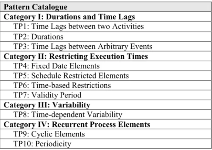
During our analyses we identified 10 different time pat- terns. We divide these into 4 distinct categories based on their semantics (cf. Fig. 5). Particularly, the time pat- terns constitute solutions for representing commonly oc- curring temporal constraints in PAISs.Pattern Category I (Durations and Time Lags) provides support for ex- pressingdurations of different process granularities (i.e., activities, activity sets, processes, or sets of process in- stances) as well astime lagsbetween activities or – more generally – between process events (e.g. milestones).Pat- tern Category II (Restricting Execution Times) allows
1 translated from German
specifying constraints regarding possible execution times of single activities or entire processes (e.g., activity dead- lines).Category III (Variability) provides support for expressingtime-based variability during process execu- tion (e.g., varying control-flow depending on tempo- ral aspects). Finally,Category IV (Recurrent Process Elements) comprises patterns for expressing temporal constraints in connection with recurrent activities or process fragments (e.g., cyclic flows and periodicity).
Pattern Catalogue
Category I: Durations and Time Lags TP1: Time Lags between two Activities TP2: Durations
TP3: Time Lags between Arbitrary Events Category II: Restricting Execution Times
TP4: Fixed Date Elements TP5: Schedule Restricted Elements TP6: Time-based Restrictions TP7: Validity Period Category III: Variability
TP8: Time-dependent Variability Category IV: Recurrent Process Elements
TP9: Cyclic Elements TP10: Periodicity
System-specific Design Choices A) Parameters of a pattern may be set at
a) build-time (i.e., during process modeling)
b) process instantiation-time (i.e., when a process instance is instantiated)
c) run-time (i.e., during process execution) B) Time parameters can be specified in different time
granularities
a) Basic (i.e., years, months, weeks, days, hours, minutes, seconds)
b) System-defined (e.g., business days) c) User-defined (e.g., Wednesday afternoon)
General Design Choice
C) Patterns can be applied to different process granularities a) Single activity (including multi-instance activities) b) Activity set
c) Process model d) Set of process instances
General Design Choice for Pattern Category I D) There are three kinds of restrictions
a) Minimum value b) Maximum value
c) Time interval [min … max]
Fig. 5 Pattern Catalogue (TP = Time Pattern)
Fig. 5 gives an overview of the identified time pat- terns. For each pattern, we provide a name, synonyms, a description of the problem addressed, design choices characterizing pattern variants, remarks regarding pat- tern implementation, minimal requirements in respect to the pattern’s application context, use cases we identi- fied when analyzing practical scenarios, and a reference to related patterns (cf. Fig. 10 - Fig. 25). Thereby, two patterns are considered to be mutually related if they have any common element.
Following the approach described in [67], we usede- sign choicesfor parameterizing the time patterns. This enables us to keep the number of different patterns man- ageable. For example, there exist four different variants of pattern TP1 (Time Lags between Activities) as time lags between activities can be specified either between the start of two activities, between the start of the first and the end of the second activity, between the end of the first and the start of the second activity, or between the end of the two activities. Additional variance is in- troduced due to the different semantics of time lags, e.g., the need to distinguish between minimum and maximum time lags (cf. Fig. 10).
Design choices not only relevant for a particular pattern, but for a whole pattern group, are described only once for this group. Typically, an existing PAIS does not support all design choices regarding a specific
Time Patterns for Process-aware Information Systems 7 pattern. In this context, we denote the combination
of design choices supported by a particular approach as pattern variant. Fig. 6 depicts two system-specific design choices relevant for most of the time patterns:
Design Choice Adescribes when the parameters (e.g., duration) of the respective patterns can be set, i.e., at build-time, process instantiation-time, or run-time. De- sign Choice B describes which time granularities are supported by the PAIS. This includes basic time gran- ularities (e.g., second, minute, hour, etc.) as well as system- and user-defined time granularities (e.g., busi- ness days and personal working hours). Since design choicesAand Bare system-specific, we do not repeat them in the tables describing the specific patterns. How- ever, if not all options of design choicesAorB are valid for a given time pattern, this is commented.
Pattern Catalogue
Category I: Durations and Time Lags TP1: Time Lags between two Activities TP2: Durations
TP3: Time Lags between Arbitrary Events Category II: Restricting Execution Times
TP4: Fixed Date Elements TP5: Schedule Restricted Elements TP6: Time-based Restrictions TP7: Validity Period Category III: Variability
TP8: Time-dependent Variability Category IV: Recurrent Process Elements
TP9: Cyclic Elements TP10: Periodicity
System-specific Design Choices A) Parameters of a pattern may be set at
a) build-time (i.e., during process modeling)
b) process instantiation-time (i.e., when a process instance is instantiated)
c) run-time (i.e., during process execution) B) Time parameters can be specified in different time
granularities
a) Basic (i.e., years, months, weeks, days, hours, minutes, seconds)
b) System-defined (e.g., business days) c) User-defined (e.g., Wednesday afternoon)
General Design Choice
C) Patterns can be applied to different process granularities a) Single activity (including multi-instance activities) b) Activity set
c) Process model d) Set of process instances
General Design Choice for Pattern Category I D) There are three kinds of restrictions
a) Minimum value b) Maximum value
c) Time interval [min … max]
Fig. 6 System-specific Design Choice
Design Choice C, which is depicted in Fig. 7, is a general design choice being valid for several patterns. It describes the process granularities (i.e., activity, activ- ity set, process, set of process instances) to which the respective pattern can be applied (e.g., to constrain the duration of a single activity or of all instances created from a particular process schema). In this context, a process refers to a process schema as well as to cor- responding process instances. In general, a pattern is applied to the respective process schema, whereas its parameters may be specific for the particular process instance (i.e., each process instance has its own value).
For example, consider an appointment for an activity.
While the existence of the appointment is known at process schema level, its date and time is determined during the execution of the respective process instance.
The instances belonging to aset of process instances, in turn, may be enacted based on the same process schema, but may also run on different process schemes. In the latter case, these process instances share common char- acteristics linking them with each other (e.g., process instances referring to different medical examinations of
the same patient). Though we do not explicitly consider sub-processes in the following discussions, all patterns that may be applied to a process, can be applied to sub-processes as well. For each pattern, the process granularities to which the pattern may be applied are explicitly listed.
Pattern Catalogue
Category I: Durations and Time Lags TP1: Time Lags between two Activities TP2: Durations
TP3: Time Lags between Arbitrary Events Category II: Restricting Execution Times
TP4: Fixed Date Elements TP5: Schedule Restricted Elements TP6: Time-based Restrictions TP7: Validity Period Category III: Variability
TP8: Time-dependent Variability Category IV: Recurrent Process Elements
TP9: Cyclic Elements TP10: Periodicity
System-specific Design Choices A) Parameters of a pattern may be set at
a) build-time (i.e., during process modeling)
b) process instantiation-time (i.e., when a process instance is instantiated)
c) run-time (i.e., during process execution) B) Time parameters can be specified in different time
granularities
a) Basic (i.e., years, months, weeks, days, hours, minutes, seconds)
b) System-defined (e.g., business days) c) User-defined (e.g., Wednesday afternoon)
General Design Choice
C) Patterns can be applied to different process granularities a) Single activity (including multi-instance activities) b) Activity set
c) Process model d) Set of process instances
General Design Choice for Pattern Category I D) There are three kinds of restrictions
a) Minimum value b) Maximum value
c) Time interval [min … max]
Fig. 7 General Design Choice
Finally, additional design choices only relevant for a specific pattern (category) are introduced in connection with this pattern (category).
4.1 Pattern Category I: Durations and Time Lags The first pattern category we consider comprises three time patterns expressing durations for different kinds of process granularities (e.g., activities) as well as time lags between activities or events. These patterns not only enable us to restrict processes and their activities in terms of minimum/maximum durations, but also de- scribe general temporal properties of a process (e.g., a critical path2). Knowledge about temporal properties is especially relevant for scheduling activities and for allo- cating resources (e.g., expressing how long a particular resource may be used by a certain activity or process).
Further, it can be used for predicting execution times of not yet enabled activities (e.g., “activity B will be enabled tomorrow morning”) [46, 23].
Time lags and durations can be specified in terms of minimum/maximum values as well as time intervals (cf.
Fig. 8,Design Choice D). The latter represent both a minimum and a maximum value at the same time; e.g., the constraint “between 2 and 3 hours” can be expressed using 2 hrs as minimum and 3 hrs as maximum. Hence, Design Choice D constitutes a general design choice being valid for all patterns from Category I (cf. Fig. 8).
4.1.1 Pattern TP1 (Time Lags between two Activities) This pattern allows defining time lags between two activ- ities; i.e., to express a minimum or maximum temporal distance between them. For example, pattern TP1 may
2 A critical path is a sequence of activities within a process schema, which add up to the longest overall process duration.
Its length determines the shortest time to complete the process.
8 Andreas Lanz et al.
Pattern Catalogue
Category I: Durations and Time Lags TP1: Time Lags between two Activities TP2: Durations
TP3: Time Lags between Arbitrary Events Category II: Restricting Execution Times
TP4: Fixed Date Elements TP5: Schedule Restricted Elements TP6: Time-based Restrictions TP7: Validity Period Category III: Variability
TP8: Time-dependent Variability Category IV: Recurrent Process Elements
TP9: Cyclic Elements TP10: Periodicity
System-specific Design Choices A) Parameters of a pattern may be set at
a) build-time (i.e., during process modeling)
b) process instantiation-time (i.e., when a process instance is instantiated)
c) run-time (i.e., during process execution) B) Time parameters can be specified in different time
granularities
a) Basic (i.e., years, months, weeks, days, hours, minutes, seconds)
b) System-defined (e.g., business days) c) User-defined (e.g., Wednesday afternoon)
General Design Choice
C) Patterns can be applied to different process granularities a) Single activity (including multi-instance activities) b) Activity set
c) Process model d) Set of process instances
General Design Choice for Pattern Category I D) There are three kinds of restrictions
a) Minimum value b) Maximum value
c) Time interval [min … max]
Fig. 8 General Design Choice for Category I
Examination Administer
Contrast Medium
minimum 2 hours
maximum 3 hours
Fig. 9 Minimum and Maximum Time Lags between Activities
be applied to ensure compliance with business rules and global regulations.
Example 2 (Minimum and maximum time lag between two activities) Consider a medical examination con- ducted in the radiology department and assume that a contrast medium must be given to the patient prior to the examination (cf. Fig. 9). On the one hand, in order to ensure that the contrast medium is properly distributed in the patient’s body, this activity has to be accomplished at least 2 hours before the radiolog- ical examination takes place. On the other hand, the contrast medium must not be administeredmore than 3 hours ahead of the examination; otherwise it might have been already decomposed in the body and thus the examination would not lead to any meaningful result.
In Example 2, there exists aminimum time lag of 2 hours between delivery of the contrast medium and start of the medical examination. Furthermore, there is amaximum time lag of 3 hours between delivery of the drug and completion of the examination (cf. Fig. 9).
Such time lags can be expressed using time pattern TP1.
Details about this pattern are given in Fig. 10. It can only be applied to activities (Design Choice C[a]). Ad- ditional pattern variants can be expressed using design choices D and E. Design Choice D (cf. Fig 8) allows choosing among maximum time lag, minimum time lag, and time interval (cf. Example 2). In turn,Design Choice E (cf. Fig. 10) specifies whether aTime Lag rep-
resents a start-start relation (i.e., referring to the start event of two different activities), a start-end relation, an end-start relation, or an end-end relation. Reconsider Example 2, for which the minimum time lag between the two activities corresponds to an end-start relation and the maximum time lag to an end-end relation.
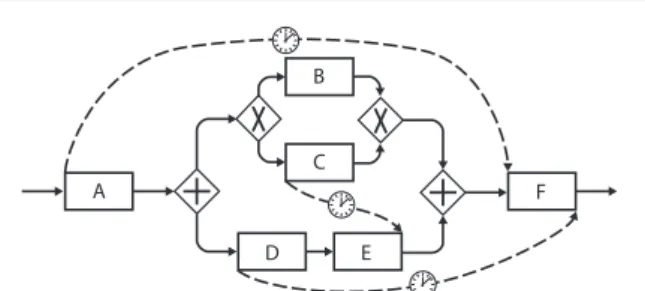
In general, Time Lags cannot be only expressed between two directly succeeding activities, but also be- tween arbitrary activities (e.g., contained in different regions of a sequence or belonging to different paral-
A
B
C
D E
F
Fig. 11 Time Lags between Arbitrary Activities
lel branches), presuming that these may belong to the same process instance. In particular, aTime Lag is not allowed between two alternative activities. For example, consider the process model from Fig. 11. Here, Time Lagsare specified between activitiesAandF, activities D andF, and activitiesC andE. However, no Time Lagmust be specified betweenB andC since these two activities will never be executed together for the same process instance.
4.1.2 Pattern TP2 (Durations)
Durations constitute one of the most frequently used temporal constraint in PAISs. Usually, they are required to ensure compliance of processes with global rules and regulations, to guarantee adherence to external bench- marks (e.g., policies, service level agreements), or to limit resource usage.
Example 3 (Maximum duration) Due to service level agreements between an on-line book store and its cus- tomers, the handling of an order must not take longer than 1 day (express shipping). Otherwise, the customer is entitled to get a partial refunding (exception han- dling).
Minimum durationsare frequently required for plan- ning purpose, e.g., to determine how long a resource will be at least occupied or to identify the earliest possible point in time for scheduling succeeding activities.
Example 4 (Minimum duration)Cleaning an operating room after a surgery takes at least 30 minutes. Therefore, a surgery must not be scheduled earlier than 30 minutes after completing the previous one.
Time pattern TP2 is described by Fig. 12. It allows specifying the duration of an element of any process granularity (i.e., activity, activity set, process, or set of process instances) (cf.Design Choice C, Fig. 12). In addition to Design Choice C, pattern TP2 supports Design Choice D(cf. Fig. 12).
Time Patterns for Process-aware Information Systems 9
Time Pattern TP1: Time Lags between two Activities
Also known as Upper and Lower Bound Constraints, Inter-Task Constraints, Temporal Relations Problem
There is a time lag between two activities to be obeyed. Such Time Lags may not only be defined between directly succeeding activities, but also between arbitrary ones (presuming that the activities may belong to the same process instance).
Design Choices
C) Time lags only constrain the execution of activities C[a] (cf. Fig. 7) D) Time lags may represent all three kinds of restrictions (cf. Fig. 8) E) Time lags define the distance between the
a) start of two activities (i.e., Start-Start relation)
b) start of the first and the completion of the second activity (i.e., Start-End) c) completion of the first and the start of the second activity (i.e., End-Start) d) completion of two activities (i.e., End-End)
Solution
A time constraint is introduced between the start / end event of the two activities.
Timers can be used to realize this pattern at run-time. For example, to implement an end- start relation between activities A and B, the
timer starts after completing A. If the time lag between A and B represents a minimal one, B must not be started before the timer has expired; i.e., the execution of activity B is delayed until the time lag is satisfied. If the time lag expresses a maximum distance, B may be started immediately, but has to be started latest when the timer expires. In case the timer expires an exception handling may be triggered. For time intervals both cases apply.
Context The mechanism evaluating the constraint (i.e., starting the timer) needs to be able to access the value of the time lag when starting the timer.
Examples
The maximum time lag between discharging a patient from a hospital and sending out the discharge letter to the general practitioner treating the patient is 2 weeks (Design Choices D[b] E[d] )
Patients must not eat at least 12 hours before a surgery takes place. The latest point in time at which the patient can have a meal is therefore determined by the date of the surgery (Design Choices D[a] E[c] )
The time lag between registering a Master thesis and submitting it must not exceed 6 months (Design Choices D[b] E[a] )
Related Patterns
TP2 (Durations): TP1 and TP2 both refer to the time lag between process events.
TP3 (Time Lags between Events): TP1 can be implemented based on pattern TP3.
TP9 (Cyclic Elements): TP9 is an extension of TP1, considering cycles and iterations.
Fig. 10 TP1 - Time Lags between Activities
4.1.3 Pattern TP3 (Time Lags between Arbitrary Events)
Certain events cannot be bound to the start or end of an activity or process. For example, there may be events triggered by external sources not controllable by the PAIS. e.g., receiving a message from a partner process or an event in the physical world [70]. In addition, there may be events not bound to a specific activity, e.g., event
“delivery of all parts” requires several activities and processes, respectively, to be completed. Finally, there may be events triggered inside a long-running activity, e.g., when reaching a milestone during the execution of a long-running activity or sub-process. Time pattern TP3 enables the specification ofTime Lagsbetween two arbitrary discrete events.
Example 5 (Minimum time lag between two message events) In product development, usually, well-defined
processes for realizing product changes and for getting the approval required from the concerned partners exist.
For a change management process (cf. Fig. 13), typically, a maximum time lag between sending a request for approval (for a product change) to a supplier (event) and getting a corresponding response (event) can be found.
Partner A
Partner B
Time Lags between Events Send Request
for Approval
Receive Approval
Fig. 13 Time Lag between two Message Events
10 Andreas Lanz et al.
Time Pattern TP2: Durations Also known as -
Problem
A particular activity, activity set, process, or set of process instances has to obey a certain duration restriction.
Durations result from both waiting (i.e., activity is suspended) and processing times during activity execution. However, a duration does not cover the time span the activity (activity set, process or process instance) is offered in user worklists but has not been started by any user yet (i.e., the time span between activation and start of the activity).
Design Choices C) Durations may be applied to all four kinds of process granularities (cf. Fig. 7) D) Durations may represent all three kinds of restrictions (cf. Fig. 8)
Solution
A time constraint is introduced between the start and end events of an activity (the same applies to activity sets, processes and process instances).
Timers can be used to enable run-time support for durations. For minimum (maximum) durations the respective activity must not complete before (after) the timer has expired, otherwise appropriate exception handling needs to be initiated. For time intervals, the end event has to occur within the time interval boundaries.
Context
The mechanism evaluating the constraint (i.e., starting the timer) needs to be able to access the value of the duration before starting the activity (activity set, process or process instance).
Examples
The assembly of a new engine must not take longer than 30 minutes (task work) (Design Choices C[b] D[b])
Depending on its severity and the patient’s state, ovarian cancer surgeries take 1 to 10 hours (Design Choices C[a] D[c]).
Maintenance issues need to be resolved within 1hr (Design Choices C[c] D[b])
Processing 100 requests must not take longer than 1 second (Design Choices C[d] D[b]) Related Patterns
TP1 (Time Lags between Activities): TP1 and TP2 both refer to the time lag between process events.
TP3 (Time Lags between Events): TP2 can be implemented based on TP3.
Fig. 12 TP2 - Durations
Pattern TP3 is described by Fig. 14. As opposed to pattern TP1, which only supports time lags between activities, TP3 provides more generic support for ex- pressing arbitrary time lags in PAISs. In general, time patterns TP1 and TP2 can be expressed using pattern TP3. However, since their semantics and use cases are quite different (e.g., regarding escalation handling or the enforcement of compliance with a temporal constraint in the PAIS), we added all three patterns to our pattern catalogue. Similarly to time patterns TP1 and TP2, pattern TP3 supports Design Choice D (cf. Fig. 14) in order to specify whether a time lag expresses a minimum value, a maximum value, or a time interval.
4.2 Pattern Category II: Restricting Execution Times This category comprises four patterns for restricting the execution times of an activity or process (e.g., earliest start or latest completion time). Time patterns from this
category enable a PAIS to properly time the execution of activities and process instances (cf. TP4: Fixed Date Element), to bind the execution of an activity or process to an external schedule (cf. TP5: Schedule Restricted Element), to limit the number of executions of an activ- ity (process) within a particular time frame (cf. TP6:
Time-based Restrictions), or to restrict the lifetime of an activity or process (cf. TP7: Validity Period).
Regarding time patterns from Category II,Design Choice F describes what kind of date is specified by the respective constraint, i.e., we differentiate between earliest start, latest start, earliest completion, and latest completion date (cf. Fig. 15). As example consider the submission deadline of a Master thesis. Enforcing a cer- tain completion date, for example, would be too strict as it is also possible to submit the thesis prior to the submission deadline. Therefore, it should be possible to not only restrict the start or completion date of an activity, but alternatively to only restrict the earliest
Time Patterns for Process-aware Information Systems 11
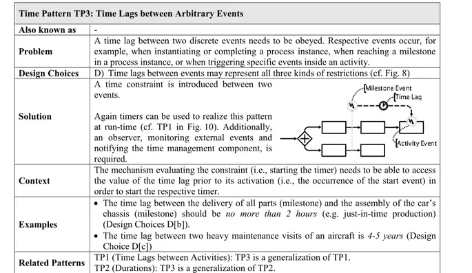
Time Pattern TP3: Time Lags between Arbitrary Events Also known as -
Problem
A time lag between two discrete events needs to be obeyed. Respective events occur, for example, when instantiating or completing a process instance, when reaching a milestone in a process instance, or when triggering specific events inside an activity.
Design Choices D) Time lags between events may represent all three kinds of restrictions (cf. Fig. 8)
Solution
A time constraint is introduced between two events.
Again timers can be used to realize this pattern at run-time (cf. TP1 in Fig. 10). Additionally, an observer, monitoring external events and notifying the time management component, is required.
Context
The mechanism evaluating the constraint (i.e., starting the timer) needs to be able to access the value of the time lag prior to its activation (i.e., the occurrence of the start event) in order to start the respective timer.
Examples
The time lag between the delivery of all parts (milestone) and the assembly of the car’s chassis (milestone) should be no more than 2 hours (e.g. just-in-time production) (Design Choices D[b]).
The time lag between two heavy maintenance visits of an aircraft is 4-5 years (Design Choice D[c])
Related Patterns TP1 (Time Lags between Activities): TP3 is a generalization of TP1.
TP2 (Durations): TP3 is a generalization of TP2.
Fig. 14 TP3 - Time Lags between Events
start, latest start, earliest completion, or latest com- pletion date. In the given case, for example, only the latest completion date of the respective activity should be restricted.
General Design Choice for Pattern Category II F) Patterns can restrict four dates of an activity (process)
a) Earliest start date, b) Latest start date, c) Earliest completion date, d) Latest completion date
Fig. 15 General Design Choice for Category II
4.2.1 Pattern TP4 (Fixed Date Element)
Besides durations, TP4: Fixed Date Elements consti- tutes another frequently applied pattern for specifying temporal constraints (according to our analysis). In par- ticular, TP4: Fixed Date Elements allows specifying that a particular activity or process instance must be executed at a fixed date.
Example 6 (Fixed date element) A patient has an ap- pointment for a medical examination next Monday at 10 am. Due to a tight schedule of the physician, it may well be that after his arrival the patient has to wait some time before the examination can start (i.e., the earliest possible start date is given).
Time pattern TP4 allows expressing such deadline constraints. It is described in Fig. 16. Fixed Date El- ements can be applied to an activity or process (De- sign Choice C[a, c], cf. Fig. 16). Parameter values of a Fixed Date Element, however, are specific to a pro- cess instance, i.e., they are not known before creating a process instance. Therefore, it is not possible to set all parameter values of the respective pattern already at build-time, i.e.,Design Choice A[a] (cf. Fig. 16) is not applicable to pattern TP4. For a particular activity or process instance, it can be defined whether it has to be started after, started before, completed after, or completed before a particular date (Design Choice F, cf.
Fig. 16).
Fixed Date Elements may have a great influence on the temporal properties of a process (e.g., length of the critical path, scheduling of other activities) as they fix executions time of activities. Thus, they implicitly restrict the latest (earliest) start (completion) time of preceding (succeeding) activities as well.
Example 7 (Deadline) The flight from Munich to Ams- terdam leaves at 6:05 am. All process activities prior to the flight need to be completed by this time.
4.2.2 Pattern TP5 (Schedule Restricted Element) TP5: Schedule Restricted Elementsallows restricting the
execution of a particular activity or process through a
12 Andreas Lanz et al.
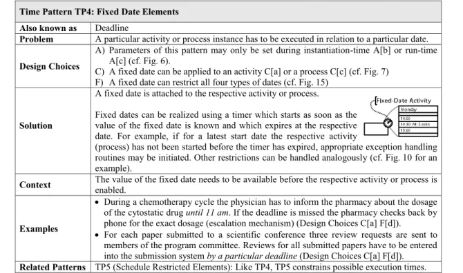
Time Pattern TP4: Fixed Date Elements Also known as Deadline
Problem A particular activity or process instance has to be executed in relation to a particular date.
Design Choices
A) Parameters of this pattern may only be set during instantiation-time A[b] or run-time A[c] (cf. Fig. 6).
C) A fixed date can be applied to an activity C[a] or a process C[c] (cf. Fig. 7) F) A fixed date can restrict all four types of dates (cf. Fig. 15)
Solution
A fixed date is attached to the respective activity or process.
Fixed dates can be realized using a timer which starts as soon as the value of the fixed date is known and which expires at the respective date. For example, if for a latest start date the respective activity
(process) has not been started before the timer has expired, appropriate exception handling routines may be initiated.Other restrictions can be handled analogously (cf. Fig. 10 for an example).
Context The value of the fixed date needs to be available before the respective activity or process is enabled.
Examples
During a chemotherapy cycle the physician has to inform the pharmacy about the dosage of the cytostatic drug until 11am. If the deadline is missed the pharmacy checks back by phone for the exact dosage (escalation mechanism) (Design Choices C[a] F[d]).
For each paper submitted to a scientific conference three review requests are sent to members of the program committee. Reviews for all submitted papers have to be entered into the submission system by a particular deadline (Design Choices C[a] F[d]).
Related Patterns TP5 (Schedule Restricted Elements): Like TP4, TP5 constrains possible execution times.
Fig. 16 TP4 - Fixed Date Elements
schedule; i.e., a timetable (e.g., a bus schedule). Typi- cally, the structure of the schedule is known at built-time, whereas the concrete dates are determined either at cre- ation or run-time of a process instance, e.g., when a particular activity is scheduled. The schedule provides restrictions on when the respective activity or process may be executed.
Example 8 (Schedule restricted element)Opening hours of the dermatological clinic are MO - FR, 7 am - 6 pm except for public holidays. Dermatological examinations can only be scheduled within this time frame.
Time pattern TP5 allows expressing constraints of this kind (cf. Fig. 17). In detail, it allows restricting the possible execution times of an activity or process through aschedule. A schedule itself consists of a (pos- sibly infinite) set of time slots described by a finite expression based on a calendar (e.g., “MO - FR, 8 am - 5 pm”) (see [?,?]). Each time slot, in turn, specifies atime frameduring which the respective event of the activity may occur.
Example 9 (Schedule and time slots)Consider the sched- ule presented in Example 8. It is described by expression
“MO - FR, 8 am - 5 pm except for public holidays”. For example, this schedule contains the time slots “Monday, February 14. 2011, 8 am till 5 pm”, “Tuesday, February 15. 2011, 8 am till 5 pm”, and so forth.
As listed in Fig. 17, aSchedule Restricted Element can be applied to an activity and process, respectively (Design Choice C[a, c]). Further, it can be used to re- strict the earliest start, latest start, earliest completion, and latest completion of the respective activity or pro- cess (Design Choice F). More precisely, as a schedule consists of several time slots, it always restricts both the earliest and latest start or the earliest and latest completion date of the respective activity or process.
Additionally, exceptions related to a given schedule can be explicitly defined (e.g., “every Monday except for public holidays”).
For highly restricted schedules, even small delays during process execution may have significant conse- quences; e.g., if a particular time slot of the schedule is no longer valid, i.e., the activity may no longer be executed within the respective time slot. This will be especially critical if schedule restricted elements being on acritical path are affected by the delay or the con- cerned path itself becomes a critical path due to this delay.
Example 10 (Effects caused by a delay)The local weekly newspaper has as a submission deadline for advertise- ments every Thursday at 11 am. If this deadline is missed, there will be a delay of 1 week for publishing the respective advertisement causing delays for succeed- ing activities as well.
Time Patterns for Process-aware Information Systems 13
Time Pattern TP5: Schedule Restricted Elements Also known as -
Problem
The execution of a particular activity or process is restricted by a schedule. This schedule provides restrictions on when the respective element may be executed, i.e., the schedule defines time slots in which the respective activity may be started or completed. Usually, the structure of the schedule is known at build-time, while the concrete date is set during run- time (i.e., at the process instance level). Schedules may contain exceptions (e.g., every year except leap years).
Design Choices C) A schedule can be applied to an activity C[a] or process C[c] (cf. Fig. 7) F) A schedule can restrict all four types of dates (cf. Fig. 15)
Solution
A schedule is attached to the respective activity or process.
A schedule restriction can be realized using a timer which is
started at process instantiation time and expires at the first endpoint of one of the respective time slots (i.e., when entering or leaving a valid time frame of the particular schedule). The timer is then reset and its expiration date is set to the next endpoint of one of the time slots.
This is repeated until the respective activity (process) has been started / completed (cf.
Design Choice F) or no more valid time slots are available according to the schedule.
Outside of a valid time slot the start of the respective activity (process) should be prevented by the system. If the completion of the respective activity (process) does not occur within a valid time slot or there is no longer a valid time slot available according to the schedule, exception handling is required.
Context The structure of the schedule needs to be known before the activity or process becomes available for execution.
Examples
From Munich to Amsterdam there are flights at 6:05 am, 10:30 am, 12:25 pm, 5:35 pm and 8:40 pm (Design Choice C[a]).
Comprehensive lab tests in a hospital can only be done from MO – FR between 8 am and 5 pm (Design Choices C[a])
Related Patterns
TP4 (Fixed Date Elements): Schedule Restricted Elements often become Fixed Date Elements when a certain element of the schedule gets selected.
TP6 (Time-based Restrictions): Like Schedule Restricted Elements, they constrain possible execution times.
TP8 (Time-dependent Variability): Time-dependent Variability is often used to provide alternatives for Schedule Restricted Elements.
Fig. 17 TP5 - Schedule Restricted Element
As a consequence,Schedule Restricted Elements are often treated likeFixed Date Elementsas soon as the possible execution time is constrained, i.e., a particular time slot of the schedule is selected (e.g., a particular week is chosen for publishing an advertisement in the local weekly newspaper).
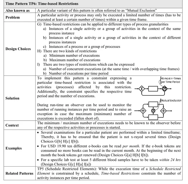
4.2.3 Pattern TP6 (Time-based Restrictions)
Sometimes, it becomes necessary to restrict the number of times a particular activity or process may be executed within a predefined time frame.
Example 11 (Time-based restriction) Two invasive ex- aminations for one and the same patient must not be performed at the same day.
Additionally,Time-based Restrictions are often re- quired to express the influence of resource restrictions (e.g. resource shortage) on process execution.
Example 12 (Mutual exclusion) For different patients two X-ray activities cannot be executed at the same time as the X-ray machine cannot be shared.
Time pattern TP6 enables such restrictions. It is de- scribed in Fig. 18.Design Choice G describes to which process granularities the pattern may be applied (cf.
Fig. 18). Depending on the context, for example, two X-ray examinations of the same patient may be mod- elled as two different activities in a single process, two activities belonging to different process instances shar- ing a common characteristics (i.e., the patient), or two different process instances. In addition,Design Choice H allows specifying whether a minimum or maximum number of executions of the respective activities (pro- cesses) is given (cf. Fig. 18). Finally, TP6 either restricts the number of concurrent executions of the activity (pro- cess) or the overall number of executions per time period (Design Choice I, cf. Fig. 18).
14 Andreas Lanz et al.
Time Pattern TP6: Time-based Restrictions
Also known as A particular variant of this pattern is often referred to as “Mutual Exclusion”
Problem A particular activity or process may only be executed a limited number of times (has to be executed at least a certain number of times) within a given time frame.
Design Choices
G) Time-based restrictions can be applied to different types of process granularities a) Instances of a single activity or a group of activities in the context of the same
process instance
b) Instances of a single activity or a group of activities in the context of different process instances
c) Instances of a process or a group of processes H) There are two kinds of restrictions
a) Minimum number of executions b) Maximum number of executions
I) There are two types of restrictions which can be expressed
a) Number of concurrent executions (at the same time / with overlapping time frames) b) Number of executions per time period
Solution
To implement this pattern a constraint expressing a particular time-based restriction is associated with the activities (processes) affected by this restriction.
Additionally, the constraint specifies the respective time period and the number of executions.
During run-time an observer can be used to monitor the number of running instances per time period and to raise an exception in case the maximum (minimum) number of executions is exceeded (fallen short of).
Context The minimum / maximum number of executions needs to be known to the observer before any of the respective activities or processes is started.
Examples
Several examinations for a particular patient are performed within a limited timeframe;
Thereby, it has to be ensured that the patient is not x-rayed several times (Design Choices G[b] H[c] I[b]).
For USD 19.90 ten different e-books can be read per month. If the e-book tokens are consumed no more books can be read in the current month. At the beginning of the next month the book tokens get renewed (Design Choices G[a] H[b] I[b]).
For a specific lab test at least 5 different blood samples have to be taken within 24 hrs (Design Choices G[c] H[a] I[a])
Related Patterns
TP5 (Schedule Restricted Elements): While the execution time of a Schedule Restricted Element is constrained by a schedule, Time-based Restrictions constrain the number of activity instances per time period.
Fig. 18 TP6 - Time-based Restrictions
4.2.4 Pattern TP7 (Validity Period)
In general, different versions of an activity or process may exist, but only one version shall be valid at a specific point in time.Validity Periodsare relevant, for example, in the context of process model evolution [53]
to restrict the remaining lifetime of an obsolete process implementation and to schedule the rollout of the new process version.
Example 13 (Validity period)Due to a changed law, pro- cess modelRevision A may only be used until January 1st. Afterwards, no process instances can be created based onRevision Aanymore, but process modelRevi- sion B has to be used instead.
Time pattern TP7, which is described in detail in Fig. 19, enables us to restrict the lifetime of an activity
or process to a given validity period. Similar to time pattern TP4, aValidity Period can be also applied to activities or processes (Design Choice C[a, c]). Further, it can be used to restrict the earliest start, latest start, earliest completion, or latest completion of the respective activity or process (Design Choice F). Since aValidity Period may prohibit the execution of an activity or process, its parameters need to be known at build-time or at least at creation time of a process instance, i.e., Design Choice A[c] (parameter values are set during run-time, cf. Fig. 7) is not applicable to this pattern.
Generally, aValidity Periodcannot only be bound to an activity or process, but to an invokable application service as well. In this case, Validity Period applies to all activities being associated with the respective