for Process-aware Information Systems:
A Pattern-based Analysis
Revised version
Andreas Lanz1, Barbara Weber2, and Manfred Reichert1
1Institute of Databases and Information Systems, Ulm University, Germany {Andreas.Lanz, Manfred.Reichert}@uni-ulm.de
2Quality Engineering Research Group, University of Innsbruck, Austria Barbara.Weber@uibk.ac.at
Abstract. Formal specification and operational support of time con- straints constitute fundamental challenges for any process-aware infor- mation system. Although temporal constraints play an important role in the context of long-running business processes, time support is very limited in existing process management systems. By contrast, different kinds of planning tools (e.g., calendar systems and project management tools) provide more sophisticated facilities for handling task-related time constraints, but lack an operational support for business processes. This paper presents a set of 10 time patterns to foster the systematic design and comparison of these different technologies in respect to the time per- spective. These time patterns are all based on empirical evidence from several large case studies. In order to ease use and implementation for each time pattern we provide a precise formal semantics. In addition, we provide an in-depth evaluation of selected process management systems, calendar systems and project management tools based on the suggested patterns. The presented work will not only facilitate comparison of these different technologies in respect to their support of time constraints, but also make evident that their integration offers promising perspectives in respect to time support for long-running business processes. Their widespread use will contribute to further maturation of process-aware information systems and related evaluation schemes.
1 Introduction
Formal specification and operational support of time constraints constitute fun- damental challenges for any enterprise information system. Although tempo- ral constraints play an important role in the context of long-running business processes (e.g., patient treatment, automotive engineering and flight planning) [1, 2, 3, 4], time support is rather limited in existing process management sys- tems [1, 5]. By contrast, different kinds of planning tools (e.g., calendar systems and project management tools) provide more sophisticated facilities for handling time constraints (e.g., periodic activities), but miss an operational support for
business processes. So far, there is a lack of methods for systematically assessing and comparing the time capabilities provided by these different process sup- port technologies (denoted asProcess-Aware Information Systems(PAIS) in the following).
To make PAIS better comparable and to facilitate the selection of appropriate PAIS-enabling technologies, workflow patterns have been introduced [6, 7, 8, 9].
Respective patterns provide means for analyzing the expressiveness of process modeling approaches in respect to different process perspectives. For example, proposed workflows patterns cover control flow [6], data flow [7], resources [8], activities [10], exceptions [11], and process change [9]. However, a framework for systematically evaluating PAIS in respect to their ability to deal with the time perspective is missing and is picked up by this paper. Our contributions are as follows:
1. We suggest 10time patterns to foster the comparison of existing PAIS with respect to their ability to deal with time aspects. The proposed time patterns complement existing workflow patterns and were systematically identified by analyzing a large collection of process models in healthcare, automotive engineering, aviation industry, and other domains.
2. In order to avoid disambiguities and to ease both use and implementation of the time patterns, for each time pattern we define a preciseformal semantics.
The description of this semantics is independent of a particular process meta model and is based on the (temporal) execution traces producible on a time constrained process schema.
3. We provide anin-depth evaluationof selected approaches from both industry and academia based on the proposed time patterns. The evaluation does not only consider process management systems, but also calendar systems and project planning tools in which time aspects play an important role.
Our pattern-based analysis shows that these different technologies all pro- vide support for time aspects. The presented work will not only facilitate their comparison in respect to the support of time constraints, but also foster the selection of appropriate time components when designing PAIS. Moreover, our work makes evident that their integration offers promising perspectives in re- spect to more sophisticated time support for long-running business processes, i.e., knowing the commonalities and differences will be a first step to integrate these technologies (e.g., process management and calendar systems).
Section 2 summarizes basic notions. Section 3 presents the research method employed for identifying the time patterns. Section 4 describes 10 time patterns sub-dividing them into 4 categories. In Section 5 we provide a formal semantics for each of the 10 patterns. Section 6 summarizes the results from our evaluation of selected approaches and tools. We present related work in Section 7 and conclude with a summary and outlook in Section 8.
2 Basic Notions
This section describes basic concepts and notions used in this paper.
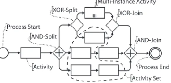
Aprocess management systemis a specific type of information system which provides process support functions and separates process logic from application code. For each business process to be supported, aprocess typerepresented by a process schemahas to be defined (cf. Fig. 1). In the following, a process schema corresponds to a directed graph, which comprises a set ofnodes – representing activitiesandcontrol connectors(e.g., XOR-Splits or AND-Joins) – and a set of control edgesbetween them. The latter specify precedence relations. We further use the notion of activity set to refer to a subset of the activities of a process schema. Its elements are not required to be part of a sequence block, but may also belong, for example, to different parallel branches. During run-timeprocess instances are created and executed according to a predefined process schema S. Activity instances, in turn, represent executions of single process steps of a particular process instance. Activities which shall be executed more than once (concurrently or sequentially) are referred to asmulti-instance activities.
The patterns introduced in the following can be applied to these granularities, i.e., process schema, activity, activity set, activity instance, and process instance.
We use the termprocess element as umbrella for all these concepts.
Activity Set Activity
Process Start AND-Split
XOR-Split XOR-Join
Multi-Instance Activity
AND-Join
Process End
Fig. 1.Core Concepts of a Process Model
3 Research Method
The overall goal of this paper is to complement existing workflow patterns (e.g., [6, 7, 8, 9, 10, 11]) with a set of time patterns suitable to assess how effectively PAIS can deal with time. As motivated in the introduction, adequate modeling and management of temporal constrains will be a key feature of future PAIS, particularly regarding the support of long-running processes involving humans (e.g., patient treatment [4] and product engineering [12]).
We describe the selection criteria for our time patterns, the data sources they are based on, and the procedure we have applied for pattern identification.
Selection Criteria. We consider patterns covering temporal aspects rele- vant for the modeling and control of processes and activities respectively. Our
focus is on a high coverage of real-world scenarios, and not on specific time features of a PAIS like verification of time constraints [2, 5, 1, 3], escalation management [13], or scheduling support [14, 15].
Sources of Data and Data Collection. As sources for our patterns we consider results of comprehensive case studies we performed in different domains, including healthcare, automotive engineering, aviation industry, and others.
One of our major data sources is a largehealthcare project in which we de- signed core processes of a Women’s Hospital [16]. Selected processes were imple- mented using existing workflow technology. As part of this project time aspects were elicited and documented. In total we consider 98 process models cover- ing both administrative processes (e.g., order handling) and treatment processes (e.g., chemotherapies and ovarian cancer surgery).
As second major data source we use process models from the automotive industry. We consider a case study on electronic change management (ECM) [17] and process models described in [18]. Some of the models related to ECM have been also published by the German Association of the Automotive Indus- try (VDA) [17]. The process models described in [18], in turn, refer to car repair and maintenance in garages, in-house change management, and product devel- opment. With several hundred activities the product development is the most complex process we consider. In total this case provides 59 process models.
As third data source serves a case study we conducted with anon-demand air service. As part of this project we analyzed and documented the flight planning and post flight phase. As the aviation industry is highly regulated, compliance with standards and regulations, in addition to company policies, is essential (e.g., minimum standards for flight time limitations, or rest time regulations). Many of these regulations contain time constraints to be obeyed.
Our fourth data source compriseshealthcare processes from a large Medical University Hospital. We consider 60 different processes, related to diagnostic and therapeutic procedures in the field of internal medicine (e.g., examinations in medical units like radiology, gastroenterology, and clinical chemistry). Finally, we have deep insight into patient scheduling systems.
Pattern Identification Procedure.To ground our patterns on a solid ba- sis we first create a list of candidate patterns. For this purpose we conducted a detailed literature review and rely on our experience with PAIS-enabling tech- nologies. Next we thoroughly analyzed the above mentioned material to find empirical evidence for our time patterns and - if necessary - extend the pat- tern candidate list. As a pattern is defined as reusable solution to a commonly occurring problem we require each of our time patterns to be observed at least three times in different models of our samples. Therefore, only those patterns, for which enough empirical evidence exists, are included in the final list of patterns, which is presented in Section 4.
4 Time Patterns
As result of our analysis we have identified 10 different patterns which we divide into 4 distinct categories (cf. Fig. 2a). These time patterns constitute solutions for realizing commonly occurring time aspects in PAIS. Pattern Category I (Du- rations and Time Lags) provides support for expressing durations of process elements (e.g., activities) as well as time lags between events (e.g. milestones) or activities. Pattern Category II (Restrictions of Process Execution Points) allows specifying constraints regarding possible execution points of process elements (e.g., activity deadline). Category III (Variability) provides support for time based variability (e.g., control-flow varies depending on time context). Finally, Category IV (Recurrent Process Elements) comprises patterns for supporting recurrent process elements (e.g., periodicity and cyclic flows).
Pattern Catalogue
Category I: Durations and Time Lags TP1: Time Lags between Activities TP2: Durations
TP3: Time Lags between Events
Category II: Restrictions of Process Execution Points TP4: Fixed Date Elements
TP5: Schedule Restricted Elements TP6: Time Based Restrictions TP7: Validity Period Category III: Variability
TP8: Time Dependent Variability Category IV: Recurrent Process Elements
TP9: Cyclic Elements TP10: Periodicity
General Design Choices
A.) Parameters of a pattern may be set at different time points a.) At build-time (i.e., during process modeling) b.) At instantiation time (i.e., when a process instance is
instantiated)
c.) At run-time (i.e., during process execution) B.) Time parameters can be specified in different time
granularities
a.) Basic (i.e., years, months, weeks, days, hours, minutes, seconds)
b.) System-defined (e.g., business days) c.) User-defined (e.g., Wednesday afternoon) C.) Patterns can be applied to different process elements
a.) Single activity (including multi-instance activities) b.) Activity set
c.) Process model d.) Set of process instances
General Design Choice for Pattern Category I D.) There are three kinds of restrictions
a.) Minimum value, b.) Maximum value and c.) Time interval [min … max]
Fig. 2a.Pattern Catalogue
Pattern Catalogue
Category I: Durations and Time Lags TP1: Time Lags between Activities TP2: Durations
TP3: Time Lags between Events
Category II: Restrictions of Process Execution Points TP4: Fixed Date Elements
TP5: Schedule Restricted Elements TP6: Time Based Restrictions TP7: Validity Period Category III: Variability
TP8: Time Dependent Variability Category IV: Recurrent Process Elements
TP9: Cyclic Elements TP10: Periodicity
General Design Choices
A.) Parameters of a pattern may be set at different time points a.) At build-time (i.e., during process modeling) b.) At instantiation time (i.e., when a process instance is
instantiated)
c.) At run-time (i.e., during process execution) B.) Time parameters can be specified in different time
granularities
a.) Basic (i.e., years, months, weeks, days, hours, minutes, seconds)
b.) System-defined (e.g., business days) c.) User-defined (e.g., Wednesday afternoon) C.) Patterns can be applied to different process elements
a.) Single activity (including multi-instance activities) b.) Activity set
c.) Process model d.) Set of process instances
General Design Choice for Pattern Category I D.) There are three kinds of restrictions
a.) Minimum value, b.) Maximum value and c.) Time interval [min … max]
Fig. 2b. General Design Choices
Fig. 2a gives an overview of the 10 time patterns, which are described in detail in the following. For each pattern we provide a name, synonyms, a brief description of the addressed problem, design choices, remarks regarding its imple- mentation including a visualization, illustrating examples from our case studies, a reference to related patterns, and known uses of the pattern summarized in a table (cf. Fig. 4 - Fig. 15).
In particular,design choices allow for parameterizing time patterns keeping the number of distinct patterns manageable. Design choices not only relevant for a particular pattern, but for several ones, are described only once. Typically, existing approaches do not support all design choices regarding a specific pattern.
We denote the combination of design choices supported by a particular approach aspattern variant.
Fig. 2b describes three general design choices concerning the point in time when temporal constraints are set, the time granularities supported and the process elements to which the respective pattern can be applied. These design choices are valid for several or all of the 10 patterns, and can be used for pa- rameterizing them. If not all options of a design choice are valid for a time
pattern this is described with the respective pattern. Additional design choices, only relevant for a specific pattern or pattern category, are provided with the re- spective description. These design choices are shortly described in the following.
The time parameters of a time pattern can be set at built-time, at instantiation time, or at run-time (Design Choice A). This has specifically great impact on the question whether, when and how the time constraints of a particular process can be validated. Furthermore the time parameters of each time pattern can have different granularities (depending on what granularities are supported by the time reference system). Typical granularities are years, months, weeks, days, hours, minutes and seconds, but also system-defined granularities (e.g., business days) or user-defined ones (e.g., Wednesday afternoon) (Design Choice B). At this point we neither consider how time granularities can be expressed nor how they can be used when verifying the temporal constraints of a process. For both of these questions several solutions have been proposed in literature [5, 1]. Fi- nally, Design Choice C describes to which process elements the pattern can be applied.
For each time pattern we provide a description using the aforementioned schema (cf. Fig. 4 - Fig. 15).
4.1 Pattern Category I (Durations and Time Lags)
Our first category comprises three time patterns expressing durations of process elements as well as time lags between them.
Design Choice D constitutes a general design choice valid for all patterns from this category. It describes whether time lags are specified in terms of min- imum/maximum values or time intervals (cf. Fig. 3).
Pattern Catalogue
Category I: Durations and Time Lags TP1: Time Lags between Activities TP2: Durations
TP3: Time Lags between Events
Category II: Restrictions of Process Execution Points TP4: Fixed Date Elements
TP5: Schedule Restricted Elements TP6: Time Based Restrictions TP7: Validity Period Category III: Variability
TP8: Time Dependent Variability Category IV: Recurrent Process Elements
TP9: Cyclic Elements TP10: Periodicity
General Design Choices
A.) Parameters of a pattern may be set at different time points a.) At build-time (i.e., during process modeling) b.) At instantiation time (i.e., when a process instance is
instantiated)
c.) At run-time (i.e., during process execution) B.) Time parameters can be specified in different time
granularities
a.) Basic (i.e., years, months, weeks, days, hours, minutes, seconds)
b.) System-defined (e.g., business days) c.) User-defined (e.g., Wednesday afternoon) C.) Patterns can be applied to different process elements
a.) Single activity (including multi-instance activities) b.) Activity set
c.) Process model d.) Set of process instances
General Design Choice for Pattern Category I D.) There are three kinds of restrictions
a.) Minimum value, b.) Maximum value and c.) Time interval [min … max]
Fig. 3. General Design Choices for Category I
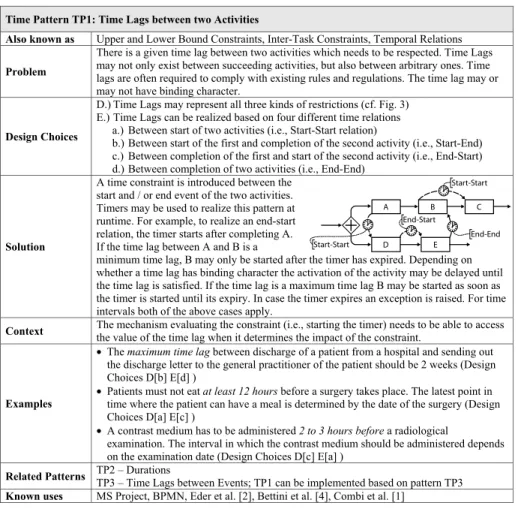
Pattern TP1 (Time Lags between two Activities). This pattern is de- scribed in Fig. 4. It enables definition of different kinds of time lags between two activities. In addition to General Design Choice D, TP1 defines one other design choice. Design Choice E describes whether the time lags describe a start-start relation (e.g., between the start event of two different activities), a start-end relation, an end-start relation, or an end-end relation.
Pattern TP2 (Durations) is described in Fig. 5. It enables specification of duration of process elements. For example, Design Choices C[a] and D[b] refer to a variant of TP2 where a maximum duration for a single activity is described (e.g., the assembly of a new engine must not take longer than 30 minutes).
End-End Start-Start
End-Start Start-Start
A B
D E
C
Time Pattern TP1: Time Lags between two Activities
Also known as Upper and Lower Bound Constraints, Inter-Task Constraints, Temporal Relations
Problem
There is a given time lag between two activities which needs to be respected. Time Lags may not only exist between succeeding activities, but also between arbitrary ones. Time lags are often required to comply with existing rules and regulations. The time lag may or may not have binding character.
Design Choices
D.) Time Lags may represent all three kinds of restrictions (cf. Fig. 3) E.) Time Lags can be realized based on four different time relations
a.) Between start of two activities (i.e., Start-Start relation)
b.) Between start of the first and completion of the second activity (i.e., Start-End) c.) Between completion of the first and start of the second activity (i.e., End-Start) d.) Between completion of two activities (i.e., End-End)
Solution
A time constraint is introduced between the start and / or end event of the two activities.
Timers may be used to realize this pattern at runtime. For example, to realize an end-start relation, the timer starts after completing A.
If the time lag between A and B is a
minimum time lag, B may only be started after the timer has expired. Depending on whether a time lag has binding character the activation of the activity may be delayed until the time lag is satisfied. If the time lag is a maximum time lag B may be started as soon as the timer is started until its expiry. In case the timer expires an exception is raised. For time intervals both of the above cases apply.
Context The mechanism evaluating the constraint (i.e., starting the timer) needs to be able to access the value of the time lag when it determines the impact of the constraint.
Examples
• The maximum time lag between discharge of a patient from a hospital and sending out the discharge letter to the general practitioner of the patient should be 2 weeks (Design Choices D[b] E[d] )
• Patients must not eat at least 12 hours before a surgery takes place. The latest point in time where the patient can have a meal is determined by the date of the surgery (Design Choices D[a] E[c] )
• A contrast medium has to be administered 2 to 3 hours before a radiological
examination. The interval in which the contrast medium should be administered depends on the examination date (Design Choices D[c] E[a] )
Related Patterns TP2 – Durations
TP3 – Time Lags between Events; TP1 can be implemented based on pattern TP3 Known uses MS Project, BPMN, Eder et al. [2], Bettini et al. [4], Combi et al. [1]
Fig. 4. TP1 - Time Lags between Activities
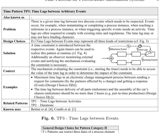
Pattern TP3 (Time Lags between arbitrary Events). TP3 is described in Fig. 6. It enables specification of time lags between two discrete events. Thus, opposed to TP1, TP3 provides more generic support for expressing arbitrary time lags. For example, respective events can be triggers from an external source (e.g., receiving a message, occurrence of a heart stroke) not controllable by the PAIS. In addition, they may refer to events which are not bound to a specific activity (e.g., event “delivery of all parts” requires several activities/processes to complete) or to events which are triggered inside an activity (e.g., milestone of an activity or subprocess, occurrence of exceptions, subprocess reaches a special state, special condition occurred).
4.2 Pattern Category II (Restrictions of Process Execution Points).
This category comprises four patterns for restricting execution points (e.g., ear- liest start or latest end time) of process elements.
Time Pattern TP2: Durations Also known as -
Problem
A particular process element has a certain duration restriction. Durations result from both waiting and processing times. Durations are often determined by external benchmarks (e.g., regulations, policies, QoS agreements). The duration may or may not have binding character.
Design Choices C.) Durations can be applied to all four kinds of process elements (cf. Fig. 2b) D.) Durations may represent all three kinds of restrictions (cf. Fig. 3)
Solution
A time constraint is introduced between the start and end event of the particular process element.
Again timers can be used to provide runtime support for durations. For minimum (maximum) durations the respective element must not complete before (after) the timer has expired, otherwise appropriate exception handling is initiated. For intervals, the completion event has to occur within the interval boundaries.
Context The mechanism evaluating the constraint (i.e., starting the timer) needs to be able to access the value of the duration before the particular element is executed.
Examples
• The assembly of a new engine must not take longer than 30 minutes (task work) (Design Choices C[a], D[b])
• Depending on its severity, ovarian cancer surgeries take 1 to 10 hours (Design Choices C[a], D[c]).
• Maintenance issues need to be resolved within 1hr (Design Choices C[c], D[b])
• Processing 100 requests must not take longer than 1 second (Design Choices C[d], D[b]) Related Patterns TP1 – Time Lags between Activities
TP3 – Time Lags between Events – TP2 can be implemented based on TP3 Known uses MS Project, BPMN, MQ Workflow, Eder et al. [2], Bettini et al. [4], Combi et al. [1]
Process Duration Activity Duration
Activity Set Duration
Fig. 5.TP2 - Durations
Regarding this category design choice F describes what kind of execution point is specified by the respective constraint (e.g., earliest start or latest end date) (cf. Fig. 7).
Pattern TP4 (Fixed Date Element). TP4 is described in Fig. 8. It provides support for specifying a deadline. For a particular process element it can be fixed whether it has to be started after, started before or completed before a particular date (Design Choice F). In many cases, fixed date elements implicitly determine latest (earliest) start (end) time of preceding (succeeding) activities as well.
Pattern TP5 (Schedule Restricted Element). TP5 is described in Fig. 9.
It enables us to restrict the execution of a particular element by a schedule; i.e., a timetable (e.g., a bus schedule). The schedule itself is known at built-time, whereas the concrete dates are specified either at instantiation or run-time. The schedule may comprise several discrete points in time, but also one or more time frames (Design Choice G).
Pattern TP6 (Time Based Restrictions) enables us to restrict the number of times a particular process element can be executed within a predefined time
Time Pattern TP3: Time Lags between Arbitrary Events Also known as -
Problem
There is a given time lag between two discrete events which needs to be respected. Events occur, for example, when instantiating or completing a process instance, when reaching a milestone in a process instance, or when triggering specific events inside an activity. Time lags are often required to comply with existing rules and regulations. The time lag may or may not have binding character.
Design Choices D.) Time Lags between Events may represent all three kinds of restrictions (cf. Fig. 3)
Solution
A time constraint is introduced between the respective events. Again timers can be used to realize this pattern at runtime (cf. Fig. 4).
Additionally an observer monitoring external events and notifying the mechanism evaluating the constraint is necessary.
Context The mechanism evaluating the constraint (i.e., starting the timer) needs to be able to access the value of the time lag in order to determine the impact of the constraint.
Examples
• Maximum time lags in an electronic change management process between sending a request for comments (by the partners affected by a change) and getting a response (Event) (Design Choices D[b]).
• The time lag between delivery of all parts (milestone) and the assembly of the car’s chassis (milestone) should be no more than 2 hours (e.g. just-in-time production) (Design Choices D[c]).
Related Patterns TP1 – Time Lags between Activities TP2 – Durations
Known uses Bettini et al. [4], Combi et al. [1]
Milestone Event
Activity Event Time Lag
Fig. 6. TP3 - Time Lags between Events
General Design Choice for Pattern Category II F.) Patterns can restrict three dates of a process element
a.) Earliest start date, b.) Latest start date, c.) Latest completion date
Fig. 7. General Design Choices for Category II
frame (cf. Fig. 10). Design Choice H describes to which process element the pattern may be applied (e.g., activity instances of a single process instance or of multiple process instances).
Pattern TP7 (Validity Period) enables us to restrict the lifetime of a process element to a given validity period (cf. Fig. 11). Design Choice F allows specifying the earliest / latest start (completion) date for the respective process element.
4.3 Pattern Category III (Variability).
This category comprises Pattern TP8 (Time Dependent Variability, see Fig. 12)which allows varying control flow depending on the execution time, or time lags between activities/events (Design Choice J). As example consider the left diagram in Fig. 12. Depending on the time the XOR-Split is executed either the upper or the lower path is chosen.
Monday
14:30 Mr. Schmith 14:00 15:00
Fixed-Date Activity Time Pattern TP4: Fixed Date Elements
Also known as Deadline Problem
A particular element has to be executed at a particular date. Fixed Date Elements often determine the latest or earliest start / completion time of preceding / succeeding activities as well. If the deadline is missed the activity or process may even become obsolete.
Design Choices C.) A fixed date can be applied to an activity (a.) or process instance (c.) (cf. Fig. 2b) F.) A fixed date can restrict all three types of dates (cf. Fig. 8)
Solution
A Fixed Date is attached to the respective element.
A Fixed Date can be realized using a timer which is started, as soon as the value of the fixed date is known and expires at the respective date. If, for example, for a latest start date
the respective element has not been started before the timer has expired appropriate exception handling is initiated.This could, for example, lead to the cancelation of the respective activity. Other restriction can be handled analogously (cf. Fig. 4 for an example).
Context The value of the fixed date needs to be available prior to the respective activity becoming available for execution.
Examples
• Assume that software is released every two weeks on Friday evening. Thus, the deadline for changes (except bug fixes) is the day before the release date (time error might lead to delays or have no effect) (Design Choices C[a] F[c]).
• To perform chemotherapy the physician has to inform the pharmacy about the dosage of the cytostatic drug until 11:00. If the deadline is missed the pharmacy checks back by phone for the exact dosage (escalation mechanism) (Design Choices C[a] F[c]).
• A patient has an appointment for an examination Monday at 10:00, but due to a full schedule of the physician it may well be that the patient has to wait until the examination starts (i.e., earliest possible execution point is given) (Design Choices C[a] F[b]).
Related Patterns TP5 – Schedule Restricted Elements; Fixed Date Elements are often schedule restricted elements as well.
Known uses MS Project, BPMN, Eder et al. [2], Bettini et al. [4], Combi et al. [1]
Fig. 8. TP4 - Fixed Date Elements
4.4 Pattern Category IV (Recurrent Process Elements).
This category comprises patterns to express cyclic elements and periodicity. De- sign Choice K is a general design choice for Category IV which describes whether the number of cycles is determined explicitly, is calculated based on time lags and end dates, or is depending on an exit condition (cf. Fig. 13).
Pattern TP9 (Cyclic Elements) allows specifying cyclic elements which are performed iteratively considering time lags between cycles (cf. Fig. 14). Design Choice L specifies whether time lags between cycles are fixed (i.e., have always same length) or may vary from iteration to iteration. Design Choice N describes whether the time lags describe a start-start relation (e.g., between the start event of two different activities), a start-end relation, an end-start relation, or an end- end relation. This pattern represents a variant / extension of pattern TP1 in which the second activity lies in the iteration succeeding the one to which the first activity belongs.
Pattern TP10 (Periodicity). TP10 allows specifying periodically recurring process elements according to an explicitperiodicityrule (cf. Fig. 15). In contrast to TP9, emphasis of TP10 is on possible execution dates of the recurrent element and not on the time lags between the iterations. Design Choice O describes whether the periodicity rule may contain one or more dates.
Time Pattern TP5: Schedule Restricted Elements Also known as -
Problem
The execution of a particular element (i.e., activity or process) is restricted by a schedule.
The structure of this schedule is known at process type level, while the concrete date is determined at instance level. The schedule provides restrictions on when the respective element can be executed. In particular, for rather restricted schedules even small delays in process execution can become critical (if schedule restricted elements being on a critical path are affected by the delay or the path becomes critical due to the delays). Schedules may contain exceptions (e.g., every year except leap years).
Design Choices
C.) A fixed date can be applied to an activity (a.) or process instance (c.) (cf. Fig. 2b) F.) A fixed date can restrict all three types of dates (cf. Fig. 8)
G.) Execution of the element can be bound to
a.) several discrete points in time (execution is only possible every full hour) or b.) one or more time frames (e.g. execution is only possible from 09:00 to 12:00)
Solution
A schedule is attached to the respective element.
A schedule restriction can be realized using a timer which is started when the process is started and expires when the first time
frame of the schedule is reached (a discrete point in time (Design Choice G[a]) can be seen as a time frame with only one time point). The timer is then reset and its expiration date is set to the end of the next time frame of the schedule. This is repeated until no more time frames are in the schedule or the process element has been started / completed (cf. Design Choice F). If the start / end of the respective element does not occur within a valid time frame or there is no longer a time frame available in the schedule, appropriate exception handling is initiated.
Context The schedule needs to be known at process type level or at least at process instantiation.
Examples
• Between Munich and Amsterdam there are flights at 6:05, 10:30, 12:25, 17:35 and 20:40 (Design Choice C[a] G[a]).
• Opening hours of the dermatological clinic are MO – FR 8:00 – 17:00 except for public holidays. Dermatological examinations can only be scheduled within this time frame (Design Choices C[a] G[b]).
• An information letter is sent by the leasing company to each customer within the first two weeks of each year (Design Choices C[a] G[b])
• Comprehensive lab tests in a hospital can only be done from MO – FR 8:00 – 17:00 (Design Choices C[a] G[b])
Related Patterns
TP4 – Fixed Date Elements (often schedule restricted elements)
TP6 – Time Based Restrictions (like schedule based restrictions constrain possible execution points for an element)
TP7 – Validity Period
Known uses MS Project, Eder et al. [2], Combi et al. [1]
Missing:
To avoid delays schedule restricted elements often become fixed date elements as soon as the execution time of the element gets fixed.
Activity
Schedule Restricted Activity
Fig. 9. TP5 - Schedule Restricted Element
5 Formalization of Time Patterns
In this section we provide a formalization of the time patterns proposed in the last section. First we give some general definitions of relevant notions likeCal- ender andTime Distance.
5.1 Basic Notions
Definition 1 (Calendar). A Calendar C is an infinite set of absolute time points without gaps (e.g. the Gregorian Calendar).
Properties:
–C is a total order; i.e., it has an ordering relation≤C and
Time Pattern TP6: Time Based Restrictions
Also known as Some occurrences of this pattern are often referred to as “Mutual Exclusion”
Problem
Particular process elements may only be executed a limited number of times within a given timeframe. Time Based Restrictions are often needed to express the influence of resource restrictions (resource shortage) onto process execution.
Design Choices
H.) Time Based Restrictions can be applied to different types of process elements a.) Instances of single activity or group of activities within same process instance b.) Instances of single activity or group of activities within different process instances
(potentially sharing some common characteristics) c.) Instances of a process or group of processes
I.) There are two types of restrictions which can be expressed by Time Based Restrictions a.) Number of concurrent executions (at same time / with overlapping time frames) or b.) Number of executions per time period
Solution
To implement this pattern a constraint expressing a particular Time Based Restriction is associated with the process elements affected by this restriction. Additionally, the constraint specifies the respective time period and the number of executions.
During runtime an observer can be used to monitor the number of running instances per time period and to raise an exception in case the maximum number of executions is exceeded.
Context The number of executions needs to be accessible by the observer before any of the respective process elements is started.
Examples
• Two invasive examinations must not be performed on same day (Design Choices I[b]).
• For USD 19.90 10 different online books can be read per month. If the book tokens are consumed no more books can be read in the current month. At beginning of next month the book tokens get renewed (Design Choices H[a] I[b]).
• During your stay at a wellness hotel you can select one treatment (free of charge) per day (Design Choices H[a] I[b]).
Related Patterns
TP5 – Schedule Restricted Elements; While the execution point of a schedule restricted element is constrained by a schedule, time based restrictions constrain the amount of activity instances / time period.
Known uses -
At most n-Times per Time Period
Mutual Exclusion
Fig. 10. TP6 - Time Based Restrictions
∀x, y∈ C:x≤Cy∨y≤Cx
Definition 2 (Time Distance).A Time Distance describes a relative distance between two points in time using a particular time granularity. LetDdenote the set of all Time Distances.
Properties:
–Dis a partial order; i.e., it has a ordering relation≤D
– The addition of a time point of a CalendarC and a Time Distance is given as
+ :C × D 7→2C
Regarding an absolute point in time t ∈ C and a time distance like
“5workingdays”∈ D, the precise semantics of the expressiont+ 5workingdays is unclear althoughtrepresents an absolute point in time (e.g., “Mon 19.10.2009 17:32.324”) and this expression can be intuitively calculated. Consequently, the exact value or meaning oft1+ 5workingdays≤t2is unclear since it is generally not known what “5 working days” or even “5 days” exactly means in the given
Time Pattern TP7: Validity Period Also known as -
Problem
A particular process element may be only executed within a particular validity period, i.e., its lifetime is restricted to the validity period. The respective process element may only be instantiated within this validity period. In general, different versions of a process element may exist, but only one is valid at a specific point in time. Validity dates are especially relevant in the context of process evolution to restrict the remaining lifetime of an obsolete process implementation and to schedule rollout of the new process.
Design Choices C.) A validity period can be applied to an activity (a.) or process instance (c.) (cf. Fig. 2b) F.) A validity period can restrict all three types of dates (cf. Fig. 8)
Solution
To realize this pattern a validity period is attached to the respective element.
Upon instantiation of the respective process element, its validity period needs to be checked. If the element does not lie within its validity period or
the duration of the element (see Fig. 5) leads to the end event being outside of the validity period, appropriate error handling is required.
Context The validity period needs to be known at process type level. If the validity period is bound to an activity it may apply to several different process types.
Examples
• Starting from Jan 1st patients need to be informed about any risks before the actual treatment takes place (Design Choice C[c] F[a]).
• From next week on the new service version should get life (Design Choice C[a] F[a]).
• Due to changed law, process A may only be used until January 1st. After this date no new process instances can be instantiated based on A, but process B has to be used instead (Design Choice C[c] F[b]).
Related Patterns TP5 – Schedule Restricted Elements TP8 – Time Dependent Variability Known uses MQ Workflow
Activity
Validity Period
Fig. 11. TP7 - Validity Period
context. It could mean, for example, that this inequation will be not fulfilled any- more at 17:30.001 on the designated day but it could also mean, that 23:59.999 the same day or even 17:29.999 the next day are still ok. This wiggle room is a general problem of time units or more exactly the meaning of time units in human understanding. For example, the statement “at most one day later” (i.e., a maximum distance of 1 day) cannot be generally mapped to an exact distance.
Since we do not want to make any restriction regarding the meaning of ex- pressions like t1+d≤ t2, we assume that in the context at hand it is always possible to decide whether or not such expression is true. Therefore we also do consider Design Choice B when defining execution semantics of the time pat- terns.
Furthermore, Design Choice A has no impact on the execution semantics proposed in this paper. The reason is that we just consider the impact the time patterns have on temporal execution traces (i.e., the execution history of a process instance). Thus the “incarnation” of the temporal constraints has already taken places and the corresponding point in time has no impact on the validity of the constraints.
We now define the notion of events as used throughout the remainder of this paper. An event denotes the occurrence of some sort of trigger during the exe- cution of a process instance. The start and end of each activity corresponding to a process instance for example, constitutes such an event (cf. Fig. 16). However, there are also external events like milestones, receipt of a message, occurrence
Time Pattern TP8: Time Dependent Variability Also known as -
Problem Depending on time aspects the control flow may vary; e.g., different branches of a process are executed or different sub process fragments are chosen.
Design Choices
J.) There are different time aspects which may be considered by an instance of this pattern a.) Execution time of an activity / process instance
b.) Time lags between activities / events
Solution
Time dependent variability can be achieved in different ways. The simplest approach is to explicitly capture the required variability in the process model through enumerating all different options. Alternatively, techniques like late binding can be used to select appropriate activity implementations during run-time depending on time. Both of these implement the variability based on the time of execution (Design Choice J[a]). Finally, the Deferred Choice Pattern may be used in combination with triggers to achieve time dependent variability based on time lags between activities (Design Choice J[b]).
Context The mechanism that evaluates the variability needs to be able to access any required data when determining which of the possible alternatives should be chosen.
Examples
•Samples which are collected between 18 and 20 o’clock and which are sent to the Department of Clinical Chemistry, need to be marked as express requests in the request form. Outside the opening hours of the clinic only emergency cases are treated (Design Choice J[a]).
• When issuing a passport the processing usually takes 4-6 weeks. If the person needs the passport earlier than 4 weeks an interim passport can be issued (Design Choice J[a]).
• Patients admitted in the hospital between 6pm and 8am are always assigned to the emergency unit (for the first night); afterwards they are transferred to a normal ward (Design Choice J[a]). Between 8am and 6pm, in turn, patients are directly admitted by the ward.
Related Patterns TP7 – Validity Dates Known uses BPMN
Deferred Choice
Minimum Time Lag Time Dependent
Late Binding
Service A Service B Service C
Time Dependent Variability
Mo-Sa 9:00-17:00
otherwise
Fig. 12. TP8 - Time Dependent Variability
General Design Choice for Pattern Category IV K.) The Number of cycles is
a.) determined by a fixed / dynamic number of iterations,
b. depends on time lag and end date or c. depends on exit condition
Fig. 13. General Design Choices for Category IV
of a heart stroke, and so forth (cf. Fig. 16). Thus, in our context we use the the notion ofeventas general term for something that happens during the execution of a process instance.
Definition 3 (Event, Event occurrence). Let PS be the set of all process schemes. The set of all events which may occur during the execution of process schema S ∈ PS is denoted as ES (without loss of generality we assume unique labeling of events in the given context).
LetC be the total set of absolute timepoints of a calendar. Then ϕ= (e, t)∈ ES× C
Time Lag between two subsequent iterations
loop
Time Pattern TP9: Cyclic Elements Also known as -
Problem A particular process element shall be performed iteratively considering time lags between the cycles.
Design Choices
C.) A cyclic element can be applied to all four kinds of process elements (cf. Fig. 2b) L.) Time Lag between cycles
a.) is fixed (e.g., 3 hours) or b.) may vary
M.) There are three kinds of restrictions (see also Design Choice D) a.) Minimum value,
b.) Maximum value and c.) Time interval [min…max]
N.) Time Lags can be realized based on four different time relations (cf. Design Choice E) a.) Between start of two activities (i.e., Start-Start relation)
b.) Between start of the first and completion of the second activity (i.e., Start-End) c.) Between completion of the first and start of the second activity (i.e., End-Start) d.) Between completion of two activities (i.e., End-End)
Solution
A special time constraint is introduced between the start and / or end event of the two process elements where the respective event of the second process element lies in the succeeding iteration of the event of the first process element.
This pattern can be realized at runtime similar to TP1 with additional attention being paid to the iterations of the respective activities.
Context
The mechanism evaluating the constraint (i.e., starting the timer) needs to be able to access the value of the time lag when it determines the impact of the constraint. Additionally Time Lags may vary between iterations (cf. Design Choice L).
Examples
• Administer 50 to 75 mg in equally divided doses every 12 hrs for 5 subsequent days (Design Choices K[a] L[a] M[c], N[c]).
• Maintenance activities for a particular aircraft have to be performed after every N flight hours (Design Choices K[c] L[a] M[b], N[c]).
Related Patterns TP10 – Periodicity
Known uses MS Project, BPMN [?], Combi et al. [?]
Fig. 14. TP9 - Cyclic Elements
denotes the occurrence of event e ∈ ES at time point t ∈ C,i.e., t defines the exact point in time at which evente occurred.
FurthermoreΦS=ES× C denotes the set of all possible event occurrences of events e∈ ES.
LetAS be the total set of activities (or more precisely activity labels) based on which process schemes S ∈ PS are specified (without loss of generality we assume unique labeling of activities in the given context). Let furthereAS denote the start-event and eAE the end-event of activity A∈ AS (cf. Fig. 16). Then, for setES the following equation holds:
{e|e≡eAS∨e≡eAE forA∈ AS} ⊆ ES
Based on events and event occurrences we now can define the notion of temporal execution trace (ortrace for short). We assume that all events related to the execution of a process instance are recorded in a temporal execution trace together with a timestamp designating their time of occurrence. Formally, temporal execution traces are defined as follows:
Time Pattern TP10: Periodicity
Also known as Recurrence, Appointment Series
Problem
A particular process element shall be performed periodically; i.e., according to a particular periodicity rule. Periodically implies some regularity, but does not necessarily mean equally distanced. A periodicity rule describes the reoccurrence pattern of the respective element (e.g., every Monday at 11:30) as well as start and end points (e.g., starting from next Monday until end of the year, 5 times). The reoccurrence patterns usually use a reference system over the given domain (e.g., a calendar). Periodicity rules may contain exceptions (e.g. every year except leap years)
Design Choices
C.) A Periodicity can be applied to all four kinds of process elements (cf. Fig. 2b) O.) The periodicity rule contains
a.) only one date (e.g., Monday at 10:00) or
b.) more than one date (e.g., Monday morning and evening)
Solution
Periodicity rules can be realized by using combinations of patterns TP1- 6, TP8 and TP9. Even for simple periodicity rules this can lead to complex processes where the periodicity rule cannot easily be recognize anymore. Therefore the periodicity as an additional layer of abstraction is necessary to describe such processes in an understandable way.
Context The contexts of the participating time patterns need to be fulfilled.
Examples
• Starting with next Monday group meetings will take place every two weeks at 11:30 (Design Choices K[c], O[a]).
• Each day at 7:00 the responsible assistant physician of the Gynaecological Clinic is informing the assistant medical director about the patients (Design Choices M[c], O[a]).
• Course ``Business Processes and Workflows'' takes place every Monday from 8:00 to 11:00 starting on Oct 6th and ending on Jan 26th. On Dec 8th, 22nd, 29th and on Jan 5th there will be no lectures taking place (Design Choices K[b], O[a]).
• Stationary chemotherapy usually comprises 6 treatments which are performed every 14 days. At the end of one treatment cycle the date for the next chemotherapy is scheduled (Design Choices K[a], O[a]).
• Administer Drug A on day 1 to 14 of each of the 6 treatment cycles and Drug B on the 1st and the 8th day. At the end of each treatment cycle the starting date for the next cycle is scheduled (Design Choices K[a], O[a]).
Related Patterns TP9 – Cyclic Elements
Known uses MS Project, BPMN [?], Combi et al. [?]
28 Days (1 Treatm ent Cycle)
1 2 3 4 5 6 7 8 9 10 11 12 1 3 14 1 5 16 17 18 19 20 21 22 23 2 3 24 2 5 26 27 28
A A A A A A A A A A A A A A
B B
Periodic Activities
Calendar
Periodicity Rule:
Administer Drug A on Day 1-14 of the treatment cycle and Drug B on Day 1 and 8
Schedule Restricted Element Time Based Restriction
Fixed-Date Element Minimum/Maximum Time Lag between iterations
Activity Duration Time Dependent Variability
Fig. 15. TP10 - Periodicity
Definition 4 (Temporal Execution Trace).Let PS be the set of all process schemes and let ES be the set of all events which may occur in process schema S∈ PS during its execution. Let furtherC be the total set of absolute timepoints of a calendar.
Let further TS denote the set of all possible temporal execution traces pro- ducible on process schema S ∈ PS. Let ΦS be the set of all possible event oc- currences and ϕ= (e, t)∈ΦS denote the occurrence of event eat time point t.
Activity Start Event Activity End Event e0
e2
e1 e4
e3
e5 eA
1S eA
1E
eA
2S eA
2E eA
3S eA
3E
eA
4S eA
4E eA
5S eA
5E
Process End Event External Event
Process Event Process Start Event
Milestone Event
Fig. 16.Events in a Process
A particular temporal execution trace τS ∈ TS is then defined as ordered set of event occurrences ϕi:
τS =< ϕ1, . . . , ϕn>
(with ϕi ∈ΦS, i= 1, . . . , n,n∈N) where the order ofϕi= (ei, ti)inτS reflects the temporal order in which the events ei occurred during the execution of a process instance running on process schemaS, i.e.
∀ϕk, ϕj∈τS :k < j⇒tk< tj.
Here, we assume that events inτS do not occur at exactly same point in time.
Additionally, in Table 1 we give some useful notions based on Definition 4 which facilitate formalization of the time patterns.
LetτS=< ϕ1, . . . , ϕn>∈ TSbe a temporal execution trace on process schema S. Then:
|τ|cardinality ofτ
τ(i) =ϕii-th item in temporal traceτ ϕ∈τ ⇐⇒ ∃i≤ |τ|withτ(i) =ϕ e∈τ⇐⇒ ∃t∈ C: (e, t) =ϕ∈τ ϕe=eandϕt=twithϕ= (e, t)
Table 1.Useful notions based on Definition 4
Furthermore, we define following functions, which returns all event occur- rences for a particular event or process element:
Definition 5 (Trace Occurrences).occurrences(S, e, τS)is a function which returns all occurrences ϕ= (e,·)of event ewithin temporal traceτS on process schema S. Formally:
occurrences:S × ES× TS 7→2ΦS with
occurrences(S, e, τS) ={ϕ|∃t∈ C:ϕ= (e, t)∈τS}
occurrences(S, A, τS, in turn, returns all occurrences of activity A within temporal traceτS of process schemaS. An occurrence of an activity is identified by the occurrence of its start and end event, i.e. (ϕS, ϕE). Formally:
occurrences:S × AS× TS 7→2ΦS×ΦS with
occurrences(S, A, τS) ={(ϕS, ϕE)|ϕS = (eAS,·)andϕE = (eAE,·)}
Note that Definition 5 implies thatoccurrences(S, e, τS) =∅holds, ife /∈τS. There are cases in which the iteration of a loop surrounding an activity needs to be explicitly taken into account, when defining patterns semantics. For example Time Pattern TP9 (cf. Fig. 14) requires the second activity to lie in the iteration succeeding the one to which the first activity belongs. For the sake of simplicity we presume nested loops here. To formally express this we define the iteration of a loop as follows:
Definition 6 (Iteration).The iteration of a loop is defined as ordered setI= (e0:n0, eL1:nL1, . . . , eLk:nLk)∈2E×N which uniquely identifies each loop and its current iteration counter with respect to a possibly surrounding loop. Thereby, e0 is the start event of the respective process instance of schema S and eLi
(1≤i≤k) is the first event of a loop;nLi (1≤i≤k), in turn, designates the iteration count of an inner loopeLi with respect to an outer loopeLi−1. Thereby the iteration counter n0 for the process instance, i.e. the start event e0 of the process instance, always has the value 1.
The Set of all possible iteration values for process schemaS ∈ PS is given asIS ⊂2E×N.
Then:iteration(S, ϕ, τS)is a function which returns the current iteration of the innermost loop surrounding event ϕe, or (e0:1) if there is no surrounding loop. Formally:
iteration:S ×ΦS× TS 7→ IS with
iteration(S, ϕ, τS) =
(e0:1)
if ϕe is not surrounded by a loop
(e0:1, eL1:nL1, . . . , eLk:nLk) else
with eLi, . . . , eLk being the first events of all loops surrounding ϕe.
This definition implies that events not belonging to the control flow are still part of the process instance and thus always have an iteration value of iteration(S, ϕ, τS) = (e0:1). As example consider Figure 17. It shows a process graph with two nested-loops. Below the process graph, a possible execution trace is given together with the respective value ofiteration(S, ϕ, τS) for each of the events in the trace.
Again Table 2 gives some useful notions based on Definition 6 which facilitate formalization of our time patterns.