Case Studies, Formal Semantics, Tool Support
Lucinéia Heloisa Thom1, Cirano Iochpe2, Manfred Reichert1, Barbara Weber3, Droop Matthias3, Gleison Samuel Nascimento2, Carolina Ming Chiao2
1 Institute of Databases and Information Systems, University of Ulm Oberer Eselsberg, 89069, Ulm, Germany
2 Institute of Informatics, Federal University of Rio Grande do Sul Av. Bento Gonçalves, 9500, 91501-970, Porto Alegre, Brazil
3Quality Engineering Research Group, University of Innsbruck, Austria
{lucineia.thom, manfred.reichert}@uni-ulm.de, {ciochpe, gsnascimento, cchiao}@inf.ufrgs.br,
barbara.weber@uibk.ac.at, matthias.droop@student.uibk.ac.at
Abstract. Recently, research on workflow activity patterns emerged in order to increase the reuse of recurring business functions (e.g., request for task execution, notification, approval and decision). While workflow patterns have been defined for several aspects related to process execution, recurrent business functions have been only partially addressed by existing work.
Related to this challenge we proposed a set of seven workflow activity patterns in previous work. In this paper we report on the results of several case studies we performed in Brazilian and European companies in order to investigate how frequently the activity patterns occur in real-world process models. We further formalize the identified activity patterns using π−calculus. This formalization as well as our analysis results are applied in the development of a BPM tool fostering the reuse of business functions specifications.
1. Introduction
In order to fulfill their business goals, companies have adopted several technologies related to the improvement of their business processes; e.g., workflow management systems and Business Process Management (BPM) tools [Dadam 2000] [Mutschler 2008]. In particular, such technologies enable the definition, execution and monitoring of the operational processes of an enterprise [Lenz, 2007], [Müller 2006], [Weske 2007], whereby different process variants may have to be managed along the process lifecycle [Hallerbach 2008].
A business process is a set of (structured) activities which jointly realize a particular business goal [Weske 2007]. Such activities are related to specific business functions or process fragments (e.g., notification, information request, approval) having a well defined semantics [Thom 2008]. In particular, a certain process fragment or business function (e.g., enabling document approval) can occur several times within one or different process models. That means multiple logical copies of the same process
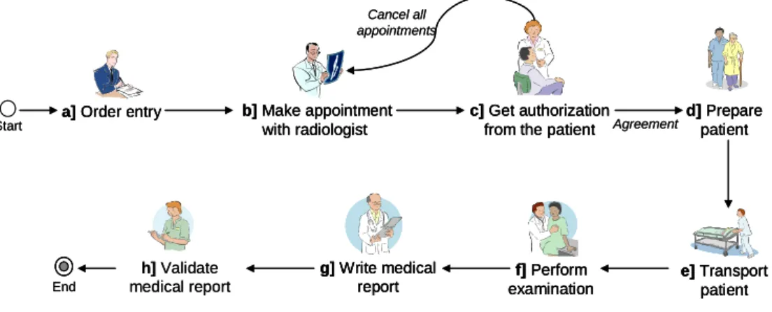
fragment may be used with same or different parameterization (e.g. approval by a single actor or by multiple actors). As example consider Figure 1, which shows the procedure for carrying out a medical examination. This process includes the following activities (in the given order): a) First an order entry is created with a request for the medical examination; b) then an appointment with the radiologist is made; c) next, an authorization from the patient for beginning his or her treatment is needed; if the patient does not agree with the treatment all appointments with the radiologist will be cancelled; d) otherwise, the patient is prepared for the examination; e) at the day of the examination the patient is transported to the radiology unit; f) the physician performs the examination; g) based on the results of the examination the physician writes a report; h) as last step, the physician who requested the examination validates the report.
g]Write medical report
f]Perform examination b]Make appointment
with radiologist a]Order entry
e]Transport patient d]Prepare
patient
End
Cancel all appointments
c]Get authorization from the patient Agreement Start
h]Validate medical report
g]Write medical report g]Write medical
report
f]Perform examination f]Perform examination b]Make appointment
with radiologist b]Make appointment
with radiologist a]Order entry
a]Order entry
e]Transport patient e]Transport
patient d]Prepare
patient d]Prepare
patient
End
Cancel all appointments
c]Get authorization from the patient c]Get authorization
from the patient Agreement Start
h]Validate medical report
Figure 1. Process for accomplishing a medical examination of a patient
Interestingly, this simple process model comprises (atomic) fragments related to activity patterns like Request for Activity Execution without Answer (Activities a, b and h), Request for Activity Execution with Answer (Activities d, e, f and g), and Approval (Activity c). In this paper we use the term Workflow Activity Pattern (WAP or activity pattern for short) to refer to the description of such business functions as they frequently re-occur in business process models.
1.1. Problem Statement
Usually, the above mentioned process fragments are re-designed for each workflow application [Flores 1998], [Medina-Mora 1992], [Malone 2004], [zur Muehlen 2002].
This lack of reusing model fragments and process knowledge, in turn, has resulted in high costs and error rates regarding the modeling and maintenance of process-oriented applications.
While some research has been reported on how metadata can be organized to manage large-scale modeling projects [Thomas and Scheer 2006], there is not much work providing evidence for the existence of activity patterns that can be used to define recurrent business functions for real-world process models. Furthermore, there is a lack of investigations proofing the necessity and completeness of respective activity patterns with respect to process modeling. Finally, contemporary BPM tools like Intalio, ARIS
Toolset and WBI Modeler do not support process designers in defining, querying and reusing activity patterns as building blocks for business process modeling.
1.2. Background and Contributions
In this paper we report on the results from ProWAP1 project, which addresses the aforementioned challenges. We first present an empirical study in which we analyze the relative frequency of the activity patterns presented in [Thom 2006b] in a collection of 239 real-world process models from application domains like quality management, software access control, textile manufacturing, and electronic change management. For selected process categories, we further discuss results of an additional analysis in which we investigate the frequency of co-occurring activity patterns.
The results of this second analysis are additionally utilized for developing a BPM tool, which shall foster the modeling of business processes based on the reuse of activity patterns [Thom 2008]. Given some additional information about the kind of process to be designed, the results of our analysis can be further used by this BPM tool to suggest a ranking of the activity patterns suited best to succeed the last pattern applied during process modeling.
Our BPM tool also provides support for analyzing and verifying model properties of composed processes like syntactical correctness or absence of deadlocks. Basic to this is a formalization of the activity patterns, which further contributes to reduce ambiguities.
Different formalisms have been suggested for defining the formal semantics of process modeling languages, including Petri Nets [van der Aalst 2003a], Temporal Logic [Eshuis 2002], and π-calculus [Puhlmann 2005]. In this paper we are using π-calculus to define formal semantics of our activity patterns. This formalism has been successfully applied before in the context of software process formalization [Szturc 1999] as well as for formalizing workflow patterns [Puhlmann 2005] and block-structured process modeling languages (e.g., XLang [Thatte 2001]).
The remainder of this paper is organized as follows: Section 2 discusses related work.
Section 3 gives background information on the workflow activity patterns we identified in previous work. Section 4 evaluates the existence and completeness of these activity patterns with respect to real-world process models. In Section 5 we provide a formalization of the patterns using π-calculus. Section 6 introduces our BPM tool which offers activity patterns to the process designer. Section 7 concludes with a summary and outlook.
2. Survey on Workflow Patterns
A pattern is the abstraction from a concrete form which keeps recurring in specific non- arbitrary contexts [Gamma 2005]. Patterns capture existing, well-proven experience in software development and help to promote good design practices [Buschmann 1996], [Eriksson 2001]. They have been used for many different domains. However, patterns for business process and workflow modeling are still subject of discussion and research.
One of the first contributions in this respect was a set of process patterns to be used in connection with the software processes of an organization [Ambler 1998].
1 http://www.uni-ulm.de/in/iui-dbis/forschung/projekte/prowap.html
Russell (2006a) proposes 43 workflow patterns for describing process. Each pattern represents a routing element (e.g., sequential, parallel and conditional routing) which can be used to process modeling. In the meantime these workflow patterns have been additionally used for evaluating process specification languages and process modeling tools [van der Aalst 2003b], [Wohed 2006]. Rinderle (2006) shows how selected control flow patterns contribute to automatically cope with certain exceptions in process-aware information systems.
A set of data patterns is proposed by [Russell 2005]. These patterns are based on data characteristics that occur repeatedly in different workflow modeling paradigms.
Examples are data visibility and data interaction. In related work, Russell presents a set of resource patterns each of them describing a way through which resources can be represented and utilized in process models [Russell 2004]. A resource is considered as an entity being capable of doing work. It can be either human (e.g., a worker) or non- human (e.g., equipment). Examples of resource patterns include Direct Allocation and Role-Based Allocation.
Recently, Russell presented a pattern-based classification framework for characterizing exception handling in workflow systems [Russell 2006b]. This framework has been used to examine the exception handling capabilities of workflow and BPM tools and to evaluate process specification as well as process execution languages accordlying. As a result, limited support for exception handling in existing workflow management systems could be observed.
Mulyar (2005) proposes 34 implementation patterns to be used in the design of process models with Colored Petri Nets tools [Mulyar 2005]. An example is the synchronous transfer pattern which allows transportation of data from one location to another, ensuring that actors who post a request are blocked until they receive the requested information.
Barros (2005) proposes a set of service interaction patterns, which allow for service interactions, pertaining to choreography and orchestration, to be benchmarked against abstracted forms of representative scenarios. As example consider the Send and the Send/Receive patterns.
Altogether Russell and Barros provide a thorough examination of the various perspectives that need to be supported by a workflow language and tool respectively.
However, none of these approaches investigate which are the most frequent patterns recurrently used during process modeling and in which way the introduction of such activity patterns eases process modeling. Furthermore, recent work has shown that consideration of the strong linkage existing between data and process allows for sophisticated IT support in all phases of the process lifecycle. For example consider the work done in COREPRO [Müller 2007], [Müller 2008] and ProCycle [Weber 2009].
This observation has not yet been fully covered in research on workflow patterns.
Obviously, broad support for workflow patterns allows for building flexible process- aware information systems. However, an evaluation of a PAIS regarding its ability to deal with process flexibility and change needs a broader view [Weber 2007], [Weber 2008a]. In addition to build-time flexibility (i.e., the ability to model flexible execution behavior based on advanced workflow patterns), run-time flexibility has to be considered as well [Reichert 1997], [Rinderle 2004]. The latter is to some degree addressed by the aforementioned exception handling patterns [Russell 2006b], which
describe different ways for coping with the exceptions occurring during process execution. To also cope with process adaptation, in addition, the aforementioned process change patterns have been introduced by [Weber 2008a], [Weber 2007]. A formalization of these change patterns is given in [Rinderle-Ma 2008]. Weber (2008b), in turn, shows how these change patterns can be used for refactoring process models in order to increase their quality.
PICTURE proposes a set of 37 domain-specific process building blocks. More precisely, these building blocks are used by end users in public administrations to capture and model the process landscape. The building blocks have been evaluated in practice [Becker 2007].
Concerning the formal representation of workflow patterns one of the first approaches used Petri Nets to formalize control flow patterns [van der Aalst 2003a]. Following this, with YAWL [van der Aalst 2005] presented a Petri-net based workflow specification language covering all control flow patterns on Petri nets.
In the context of process algebra, [Brogi 2004] used CCS (Calculus of Communicating Systems) to formalize web service flows. In another approach, CCS was used for defining a workflow modeling language called SMAWL (Small Workflow Language) [Stefansen 2005].
The π-calculus, in turn, was first used by Yang Dong and Zhang Shen-Sheng to formalize basic control flows and to define workflow activities [Dang 2003]. Based on the latter work, [Puhlmann 2005] formalize the control flow patterns described in [van der Aalst 2003a] based on π-calculus.
3. Workflow Activity Patterns
Starting with an extensive literature study (e.g., [Flores 1998], [Medina-Mora 2002], [zur Muehlen 2002]) we derived seven activity patterns. Each of them represents a fre- quently recurring business function as it can be found in real-world processes. The identified activity patterns are based on message exchanges where the sender and receiver of a particular message may belong to the same organization or to different ones the latter applies when dealing with inter-organizational processes [Dadam 2000].
Table 1 gives an overview of the seven activity patterns we identified. Generally, these patterns are close to the abstraction level or vocabulary used within an organization.
This, in turn, fosters their reuse when modeling business processes, and therefore contributes to more standardized and better comparable business process models.
We have characterized each activity pattern by giving a description, an example illustrating the context in which the pattern can be applied, a problem motivating its use specific issues arising in this context, design choices (patterns variants) which allow for pattern parameterization keeping the number of distinct patterns manageable, related patterns, and implementation details in particular. The design choices were defined based on the process models we analyzed. For example, we define three variants of the approval pattern, namely single approval (i.e., approval is required from exactly one organizational role), iterative approval (i.e., sequential approval is required from a list of reviewers) and concurrent approval (i.e., approval is required from a list of reviewers simultaneously). Information about the variants we defined for the other six patterns can be found in [Thom 2009]. Note that Table 1 only shows selected pattern variants, but
does not contain all possible parameterizations. Reason is that most of these properties are out of the scope of this paper.
Table 1. Selected variants of activity patterns representing business functions
WAP - Name Description WAP 1:
Approval
An object (e.g., a business document) has to be approved by one or more organizational roles.
WAP 2:
Question-Response
A question which emerges during process enactment has to be answered. This pattern allows to formulate the question, to identify the organizational role(s) who shall answer it, to send the question to the respective role(s), and to wait for the response(s) (single-question-response).
WAP 3:
Unidirectional Performative
A sender requests the execution of a particular task from another process participant. The sender continues process execution immediately after having sent the request for performing the activity.
WAP 4:
Bi-directional Performative
A sender requests the execution of a particular task from another process actor. The sender waits until this actor notifies him that the requested task has been performed.
WAP 5:
Notification
The status or result of an activity execution is communicated to one or more process participants.
WAP 6:
Information Request
An actor requests certain information from a process participant. He continues process execution after having received the requested information.
WAP 7:
Decision
This pattern can be used to represent a decision activity in the flow with different connectors to subsequent execution branches. Exactly those branches will be selected for execution whose transition conditions evaluate to true.
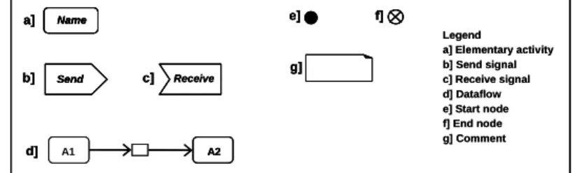
In the following sections we informally summarize pattern semantics using UML activity diagrams (cf. Fig. 2). As examples we discuss the Uni- and Bi-directional Performative Pattern and the Approval Pattern. The complete set of activity patterns is described in [Thom 2006a and Thom 2006b]. It is important to observe that the send and receive signals (cf. Fig. 2) do not configure process activities from the application domain perspective. They are used to implement the logic of the pattern.
Legend
a] Elementary activity b] Send signal c] Receive signal d] Dataflow e] Start node f] End node g] Comment Name
Send Receive
A1 A2
a]
b] c]
d]
e] f]
g]
Legend
a] Elementary activity b] Send signal c] Receive signal d] Dataflow e] Start node f] End node g] Comment Name
Send Receive
A1 A2
a]
b] c]
d]
e] f]
g]
Name Name
Send
Send Receive
A1 A2
a]
b] c]
d]
e] f]
g]
Figure 2. UML Notation used to informally summarize the activity patterns semantics
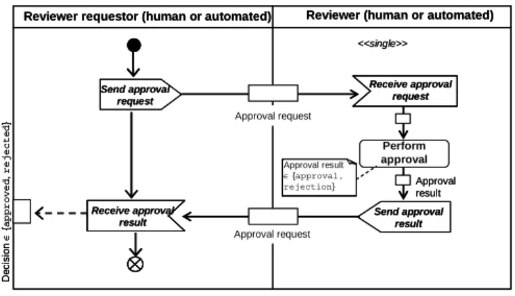
Approval Pattern (WAP 1)
An object (e.g. a document) has to be approved by one or more organizational roles.
Depending on the respective context, the evaluation is executed only once (single approval) or multiple times. In the latter variant, approval either can be accomplished in sequence (iterative approval) or in parallel (concurrent approval).
Send approval request
Receive approval request Approval request
Perform approval
Send approval result Approval request
Receive approval result
<<single>>
Approval result
∈{approval, rejection}
Decision∈{approved, rejected}
Approval result Reviewer requestor (human or automated) Reviewer (human or automated)
Send approval request
Receive approval request Approval request
Perform approval
Send approval result Approval request
Receive approval result
<<single>>
Approval result
∈{approval, rejection}
Approval result
∈{approval, rejection}
Decision∈{approved, rejected}
Approval result Reviewer requestor (human or automated) Reviewer (human or automated)
Figure 3. Approval pattern
Fig. 3 illustrates a single approval where an organizational role “reviewer” performs a document review either resulting in approval or disapproval. Generally, the Approval Pattern is related to the structural aspect “centralization on decision making”; i.e., the authority to make decisions in organizations can be more or less allocated to the highest positions within an organization (e.g., head of department, manager, director). The more centralized this authority is, the higher will be the number of organizational roles being involved in approval following the organizational scalar chain [Chiavenato, 2000].
Unidirectional Performative Pattern (WAP 3)
The unidirectional performative pattern represents a unidirectional message as described in [zur Muehlen 2002]. A sender uses unidirectional performative messages to request the execution of a particular activity from a receiver (e.g., human or software agent) involved in the process (cf. Fig. 4). The sender continues execution of his part of the process immediately after having sent the request. For example, in a procurement process, the execution of an activity to partially cancel an order can be requested from a manager if some irregularities occur. The flow continues execution after the cancel activity is requested.
Sender (activity requestor) Receiver (activity performer)
Send activity execution request
Receive activity execution request Activity request
The sender will continue execution immediatey after sending the request
Execute activity
Execution result
Sender (activity requestor) Receiver (activity performer)
Send activity execution request
Receive activity execution request Activity request
The sender will continue execution immediatey after sending the request
Execute activity
Execution result
Figure 4. Unidirectional performative pattern
Bi-directional Performative Pattern (WAP 4)
A sender requests the execution of a particular activity from another role (e.g., a human or a software agent) involved in the process. The sender waits until the receiver notifies him that the requested activity has been performed (cf. Fig. 5). As example consider a customer requesting changes concerning the design of a particular product. This triggers a process at the manufacturer site where – first of all – a designer is requested to adapt the product design according to the specifications made by the customer. The
manufacturer process then has to wait until the designer finishes this task. Afterwards the process continues with a review of the new product design by another actor.
Sender (activity requestor) Receiver (activity performer)
Send activity execution request
Receive activity execution request Activity request
The sender will block waiting for a reply to continue execution
Execute activity
Execution result
Receive notification of activity execution complete
Activity result
Send notification of activity execution complete
The sender continues execution when the receiver completes execution
Figure 5. Bi-directional performative pattern
4. Evaluating the Existence and Completeness of Activity Patterns
To identify activity patterns in real-world processes we analyzed 239 process models.
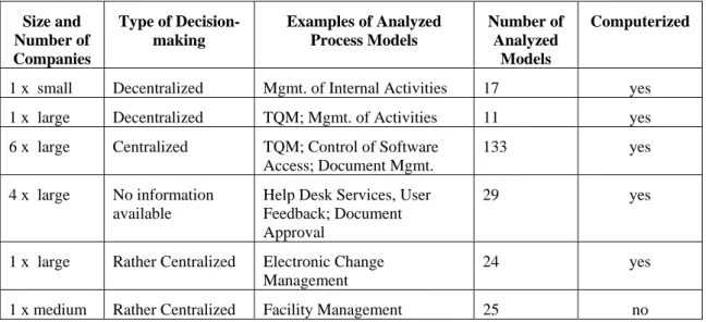
These process models have been modeled either with the Oracle Builder tool or an UML modeler. Our analysis has been based on process models instead of event logs, since we consider the semantics and the context of process activities as being fundamental for identifying activity patterns. Altogether, the analyzed process models stem from 14 different organizations – private as well as governmental ones – and are related to different applications like Total Quality Management (TQM), software access control, document management, help desk services, user feedback, document approval, textile manufacturing, and electronic change management. In most of organizations the respective process models are computerized, i.e. they are supported by a process-aware information system. Table 2 summarizes information about involved organizations and analyzed process models.
Table 2. Characteristics of the analyzed process models
Size and Number of Companies
Type of Decision- making
Examples of Analyzed Process Models
Number of Analyzed
Models
Computerized
1 x small Decentralized Mgmt. of Internal Activities 17 yes 1 x large Decentralized TQM; Mgmt. of Activities 11 yes 6 x large Centralized TQM; Control of Software
Access; Document Mgmt.
133 yes 4 x large No information
available
Help Desk Services, User Feedback; Document Approval
29 yes
1 x large Rather Centralized Electronic Change Management
24 yes 1 x medium Rather Centralized Facility Management 25 no
4.1. Applied Method
To our knowledge there exist no mining techniques for extracting activity patterns from real-world process models; i.e., contemporary process mining tools like ProM or MinAdept analyze the event logs (e.g., execution or change logs) related to process execution and do not extract information related to the semantics and the (internal) logic of process activities [van der Aalst 2003a], [Ellis 2006], [Günther 2008], [Li 2008a].
Therefore, we perform a manual analysis in order to identify relevant activity patterns as well as their co-occurrences within the 239 process models.
For each workflow activity pattern WAP* we calculate its support value SWAP*, which represents the relative frequency of the respective activity pattern within the set of analyzed process models; i.e., SWAP*:= Freq(WAP*)/239 where Freq(WAP*) denotes the absolute frequency of WAP* within the collection of the analyzed 239 models; for each process model we count at most one occurrence of a particular pattern. Reason is that in some process models, the activity patterns were identified not only in atomic activities but also in pairs (sequences) of activities.
4.2. Frequency of Activity Patterns in Real Process Models
Our analysis has shown that five out of the seven activity patterns (cf. Table 1) are not dependent on a specific application domain or a particular organizational structure (e.g., the degree of centralization in decision making or the standardization of work abilities).
Any kind of process model might contain these patterns independent of the application domain (e.g., healthcare, automotive engineering) or the kind of organization (e.g., process oriented, functional and matrix). More precisely, this applies to the following five patterns: UNIDIRECTIONAL and BI-DIRECTIONAL PERFORMATIVE (WAP 3+4), NOTIFICATION (WAP 5),INFORMATIVE (WAP6) andDECISION MAKING (WAP7). We can identify these five patterns with high frequency in almost all process models we analyzed. The APPROVAL pattern, in particular, can also be identified with high frequency because of the high degree of centralization regarding decision-making within the considered organizations. This high centralization implies the use of approval activities [Davis 1996]. By contrast, most of the analyzed process models do not contain QUESTION-ANSWER activities. Figure 7 graphically illustrates the relative frequency of each activity pattern with respect to the set of analyzed process models.
Activity Patterns - Support Value
82%
73%
56%
17%
56% 62%
0% 3%
20%
40%
60%
80%
100%
WAP1 WAP2 WAP3 WAP4 WAP5 WAP6 WAP7
WAP 1 (Approval), WAP 2 (Question-answ ering), WAP 3 (Performative Unidirectional), WAP 4 (Performative Bi-directional), WAP 5 (Notification), WAP 6 (Informative), WAPV 7I(Decision)
Figure 7. Frequency of activity patterns within real process models
4.2.1. Analyzing Process Models from an Austrian Textile Manufacturer
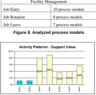
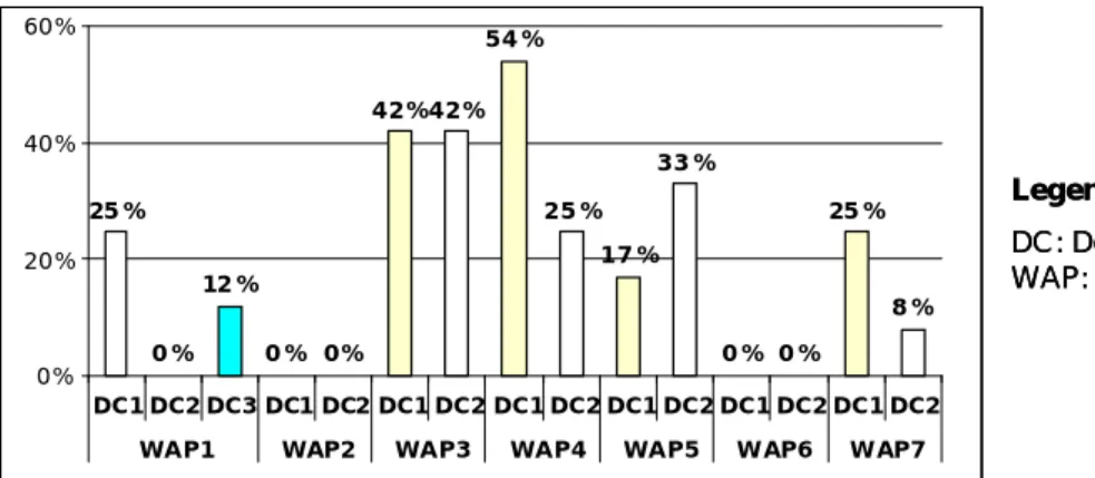
As data source we consider process models in the context of facility management. The models have been collected at a medium-sized enterprise operating in the Austrian textile industry. The decision-making within the company can be described as rather centralized. In total we analyzed 25 processes which comprise several hierarchy levels and which contain between 2 and 21 activities (for an overview see Fig. 8).
Facility Management
Job Entry 10 process models Job Rotation 8 process models Job Leave 7 process models Figure 8. Analyzed process models
Activity Patterns - Support Value
80% 88%
36% 40%
56%
12%
0% 12%
20%
40%
60%
80%
100%
WAP1 WAP2 WAP3 WAP4 WAP5 WAP6 WAP7
Figure 9. Frequency of activity patterns within Facility Management
Fig. 9 graphically illustrates the frequency of our activity patterns within the set of 25 process models from facility management. The diagram shows that the activity patterns based on organizational structural aspects (WAP 1 and WAP 2) only occur in 12% of the analyzed process models. Interestingly, WAP 1 (Approval) occurs relatively rarely for a company with centralized decision-making. This observation can be explained by the fact that the roles associated with the activities are relatively high up in the hierarchy, which reduces the need for approvals. In contrast, the activity patterns based on recurrent functions (WAP 3 – WAP 6) occur much more frequently. In 88% of all process models at least one of these patterns can be identified. WAP 4, for example, occurs much more frequently than all the other activity patterns (in average 4 times per process model). This high frequency of WAP 4 is mainly due to the nature of the analyzed process models, which primarily deal with the distribution of work.
4.2.2. Analyzing Process Models from an Automotive Company
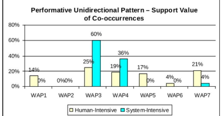
For this analysis we consider process models in the context of Electronic Change Management. The models have been collected at a large enterprise working in the automotive industry. Decision-making within the company can be described as rather centralized. In total we analyze 24 processes which have several hierarchy levels and comprise between 2 and 8 activities.
In this study for each activity pattern we determine its absolute frequency as well as its support value, which represents the relative frequency of the respective patterns within the 24 analyzed process models. We also calculate the support value by design choice
(e.g., single, iterative, concurrent approval). Fig. 10 graphically illustrates the frequency of each activity pattern within the set of 24 process models. The diagram shows that WAP1 – i.e., single approval was identified in 24% of the process models and concurrent approval in 12%. Interestingly, WAP 1 (Approval) occurs relatively rarely for a company with centralized decision-making. Like in the facility management processes (cf. Section 4.2.1), the roles associated with the activities are relatively high in the hierarchy, which reduces the need for approvals. By contrast, the activity patterns based on recurrent functions (WAP 3, WAP 5 and WAP7) occur much more frequently.
In 54% of all process models at least one of these patterns can be identified.
2
Legend
DC: Design Choice WAP: WF Activity Pattern
25%
0%
12%
0% 0%
42%42%
54%
25%
17%
33%
0% 0%
25%
8%
0%
20%
40%
60%
DC1 DC2 DC3 DC1 DC2 DC1 DC2 DC1 DC2 DC1 DC2 DC1 DC2 DC1 DC2 WAP1 WAP2 WAP3 WAP4 WAP5 WAP6 WAP7
2
Legend
DC: Design Choice WAP: WF Activity Pattern
25%
0%
12%
0% 0%
42%42%
54%
25%
17%
33%
0% 0%
25%
8%
0%
20%
40%
60%
DC1 DC2 DC3 DC1 DC2 DC1 DC2 DC1 DC2 DC1 DC2 DC1 DC2 DC1 DC2 WAP1 WAP2 WAP3 WAP4 WAP5 WAP6 WAP7
Figure 10. Frequency of activity patterns within Electronic Change Management
4.3. Identifying Co-occurrences of Activity Patterns in Real Process Models
One of the use cases for the knowledge base of our BPM tool (cf. Section 6) is based on a mechanism that gives design time recommendations with respect to the most suited activity patterns to be combined with an already used pattern. This mechanism utilizes empirical data we gathered during our case studies, which we also summarize in this section. To obtain the frequencies for pattern co-occurrences, we analyze the sequences of the co-occurring activity patterns in 154 of the 239 process models studied. When this analysis was performed only 154 of the 239 process models were available. In the future we intend to analyze the complete set of processes models, i.e., the 239 as well as further processes we might have access.
In earlier work, we have shown that when classifying the process models into human–
oriented (i.e., with human intervention during execution) and fully automated (i.e., with no human intervention during execution) we can identify certain activity patterns more often in one of the two categories [Chiao 2008]. We tried to classify the processes based on common characteristics (e.g., application domain), also considering classifications from the literature in this context. However, most of the studied classifications are based on specific application domains of the related process models [Dowson 1987], [Harrington 1991] and [Weske 2007]. Accordingly, those approaches are not applicable to our analysis because the set of the process models we have been investigating does not cover all the categories addressed by these approaches.
We therefore decided to apply Le Clair (2007) approach which classifies business processes into system- and human-intensive. System-intensive processes are character- ized by being handled on straight-through basis, i.e., there is minimal or no human intervention and few exceptions occur. Human-intensive processes, in turn, require
people to get work done by relying on business applications, databases, documents, and other actors interacting with them. This type of process requires human intuition or judgment for decision-making during individual process activities.
By classifying our set of process models in those two categories, we obtain 123 human- intensive and 31 system-intensive process models respectively. Remember that in this analysis we consider 154 of the 239 process models. The next step is to evidence the occurrence of the activity patterns in the two categories of process models. Figure 11 shows the frequency of the activity patterns with respect to system-intensive and human- intensive processes. Note that some patterns (i.e. approval, informative, question- answer) do not appear in the system-intensive process models at all. These patterns are usually related to human activities, i.e., they are executed by an organizational role.
Activity Patterns - Support Value of Co-ocurrences
73%
27%
71%
63%
75% 73% 87%
65%
68% 68%
10%
30%
50%
70%
90%
WAP1 WAP2 WAP3 WAP4 WAP5 WAP6 WAP7
Human-Intensive System-Intensive
Activity Patterns - Support Value of Co-ocurrences
73%
27%
71%
63%
75% 73% 87%
65%
68% 68%
10%
30%
50%
70%
90%
WAP1 WAP2 WAP3 WAP4 WAP5 WAP6 WAP7
Human-Intensive System-Intensive
Figure 11. Frequency of co-occurrences of activity patterns
In another analysis we search for frequent co-occurrences of activity patterns within the process models. Relying on these common occurrences the knowledge base should present to process designers a ranking of the most frequent activity patterns which normally follow the activity pattern the user has applied before for process modeling.
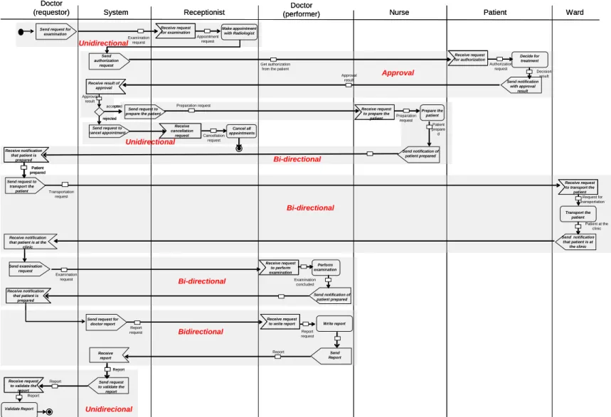
For example, Figure 12 shows how often the PERFORMATIVE UNIDIRECTIONAL PATTERN
is applied immediately after one of the other activity patterns when regarding the set of process models we analyzed. Note that for the two kinds of processes (i.e. human vs.
system intensive processes), a specific pair of patterns may occur with different frequency. For example, the pattern pair PERFORMATIVE UNIDIRECTIONAL PERFORMATIVE UNIDIRECTIONAL (WAP3)occurs more often in system-intensive than in human-intensive processes (60 % vs. 25 %). By contrast, the pair PERFORMATIVE
UNIDIRECTIONAL APPROVAL occurs more frequently in human-intensive processes.
Performative Unidirectional Pattern – Support Value of Co-occurrences
14%
0%
25%
19% 17%
4%
21%
0% 0%
60%
36%
0% 0% 4%
0%
20%
40%
60%
80%
WAP1 WAP2 WAP3 WAP4 WAP5 WAP6 WAP7 Human-Intensive System-Intensive
Performative Unidirectional Pattern – Support Value of Co-occurrences
14%
0%
25%
19% 17%
4%
21%
0% 0%
60%
36%
0% 0% 4%
0%
20%
40%
60%
80%
WAP1 WAP2 WAP3 WAP4 WAP5 WAP6 WAP7 Human-Intensive System-Intensive
Figure 12. Frequency of co-occurrences of the decision pattern within other pattern
4.4. On the Completeness of Activity Patterns for Process Modeling
When analyzing the process models our main goal was to measure the frequency with which each of the activity patterns occurs within the set of considered process models.
We did this in order to verify whether certain process fragments (e.g., task execution request, approval, notification) can be considered as patterns with high probability for reuse in the context of process modeling.
While some patterns can be identified by simply analyzing activity descriptions (e.g., in connection with decisions, approvals and notifications patterns), others require a more detailed analysis. For instance, the information request pattern (cf. Table 1) can be identified in the context of activities for which the user has to provide information to the system (e.g., by entering data via an electronic form). In case of the uni- and bi- directional performative patterns, in turn, both activity descriptions and activity results (e.g., whether results are mandatory or not to trigger the subsequent activity in the process) are important to measure how often patterns occur.
What surprises is the fact that all analyzed process models can be defined as a composition of the investigated patterns; i.e., the described set of activity patterns is necessary and sufficient to design all 239 process models that have been subject of our analysis. (Remember that Table 1 only shows selected pattern variants and does not cover all process fragments that can be configured). Furthermore, in each process, a specific activity pattern may appear multiple times in combination with other patterns.
The latter observation can be considered as very important one, which raises additional research issues. One challenging question, for example, is to what degree the identified patterns will be helpful when integrating them into a workflow modeling tool. In Section 6 we describe such a tool we are currently developing. In particular, it should foster reuse of activity patterns (cf. Section 6). Fig. 13 shows an example of a process model which has been composed solely based on the described activity patterns.
5. Formalizing Activity Patterns with π-Calculus
Basically, the activity patterns are independent of a concrete process modeling language; i.e., they can be adapted to any BPM tool if desired. In order to enable this, a precise formal semantics of the described patterns is needed. Such formal semantics is also fundamental for the correct modeling of business processes and thus for implementing robust process-aware information systems [Reichert 1998]. Thus, when composing process models out of activity patterns it is extremely important to verify their correctness.
Commercial BPM tools (e.g., Oracle BPEL Engine, Intalio), however, do not rely on a formal semantics in order to verify process model correctness. Due to this drawback, research on formal verification of process models (e.g., soundness) has received considerable attention in the research community for more than a decade. As examples of used formalisms consider Petri Nets [van der Aalst 2003a], CCS [Stefansen 2005], π−calculus [Dong 2003], [Puhlmann 2005], and trace notions (e.g., trace equivalence) [Rinderle-Ma 2008]. Respective formalisms apply mathematical methods and allow for formally specifying process models as well as related model properties or model transformations.
Send request for examination
Receive request for examination Examination
request
Doctor
(requestor) Doctor
(performer) Nurse
Receptionist
Make appointment with Radiologist
Patient
Receive request for authorization Get authorization
from the patient
Decide for treatment Authorization
request
Send notification with approval
result Receive result of
approval Send authorization
request
Send request to cancel appointment
Approval result
Receive cancellation
request
Cancel all appointments Cancellation
request rejected
accepted
Send request to prepare the patient
Receive request to prepare the
patient
Prepare the patient Preparation
request
Send request to transport the
patient
Ward
Receive request to transport the
patient
Transport the patient
Request for transportation
Send notification that patient is at the clinic Decision
result
Preparation request
Send notification of patient prepared
Patient prepare d
Receive notification that patient is
prepared
Receive notification that patient is at the
clinic
Examination request Send examination
request
Receive request to perform examination
Perform examination Transportation
request
Patient at the clinic
Examination concluded
Send notification of patient prepared Receive notification
that patient is prepared
Report request Send request for
doctor report
Receive request
to write report Write report Report request Appointment
request
Patient prepared
Unidirectional
Approval
Bi-directional
Bi-directional
Bidirectional Bi-directional Unidirectional
System
Approval result
Send Report Receive
report
Report
Validate Report Report
Send request to validate the report Receive request
to validate the report
Report
Report
Unidirecional
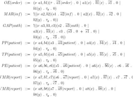
Figure 13. Real medical examination process build up exclusively from the combination of workflow activity patterns
Recently, a couple of approaches has emerged which allow to map business process models (e.g., specified with BPMN or UML) to formal process specifications (e.g., using Petri Nets or π-calculus) [Brogi 2004], [Puhlmann 2005]. Based on such formalizations, for example, it becomes possible to ensure formal process model properties (e.g., soundness [Dehnert 2005], to decide whether two process models are equivalent [Li 2008b], or to optimize and refactor process models [Weber 2008b].
In the following we propose a formalization of the activity patterns using π-calculus.
The π-calculus formalism constitutes an extension of CCS [Szturc 1999]. In particular, it allows representing the behavior of concurrent and dynamic processes. In recent work π-calculus was used to formalize business process models and workflow patterns [Smith 2003], [Puhlmann 2005]. As mentioned, there exist other methods (e.g., Petri Nets) which can be used to formalize workflow patterns [van der Aalst 2003a]. Due to their dynamic properties, however, the formalization of specific workflow patterns (e.g., advanced synchronization patterns, multi-choice patterns and cancel patterns) is not trivial when using Petri Nets. In addition, as π-calculus is based on message exchanges, it provides an efficient formalism to represent cross-organizational processes.
Our BPM tool uses the formalization of the activity patterns to create the formal representation of the process models composed out of the different patterns. Thus the composed process model can be simulated and validated already at design time in order to exclude errors. In the following we show how the activity patterns can be formally represented based on the π-calculus formalism. We first introduce the π-calculus formalism, explain how it is used to formalize the activity patterns, and finally present the formal representation of a process modelled solely based on the activity patterns.
5.1. An Introduction to π-Calculus
The π-calculus formalism was introduced by [Milner 1992]. Its underlying theory captures core characteristics of concurrent systems such as mobility and dynamics.
Basically the π-calculus consists of processes and names, whereas the names define links between the processes. For the present work we use the monadic version of the π- calculus in accordance with the following grammar (see [Milner 1992]):
P, Q ::= 0 | α.P | (ν a)P | P+Q | P|Q | !P α ::= τ | a(b) | ab | [a = b]α
Here a and b are meta-variables over elements of a countable and infinite set of names (N). Processes can be the stop process 0, prefixed process α.P, restricted process (ν a)P, sum of processes P+Q, parallel composition P|Q, and replication !P. A prefix α can be:
• a silent prefix τ.P representing an internal action of the process;
• an input prefix a(b).P , which receives a new name through a, whereupon the process P continues with all the occurrences of b substituted by the new name;
• an output prefix ab.P where the name b is sent to another process through a;
• a match prefix [a = b]α.P; i.e., if a equals b, the process will continue as α.P.
In this work we are considering the semantics as presented in [Milner 1992]; we use a graphical notation to visualize the processes. Figure 14 shows the graphical representation for the following simple process: A|B with A = a(b).0 and B = ab.0.
Figure 14. Example of Graphical Representation
In the used graphical notation, a process is represented by a circle with its name inside the circle (in the following denoted as π-process). Furthermore, the processes are connected by a line representing a communication channel between them. The end of the line, which connects the processes, represents the input prefix. It is marked with a point followed by the communication channel name.
5.2. Mapping Workflow Activities to π-Processes
Our formalization is based on the following idea: all activities contained in a process model are mapped to corresponding π-processes, whereas each π-process has its pre- and post-conditions. In principle, this corresponds to Event-Condition-Action (ECA) rules [Puhlmann 2005]. An ECA rule has three components: an Event, a Condition, and an Action. The Event component specifies when a rule must be evaluated. If an event occurs, the Condition component will have to be verified. If the condition evaluates to “true”, the Action component will have to be executed. For process models we must additionally consider other kinds of rules including Event- Condition-Action-Action (ECAA) and Event-Action (EA). It is beyond the scope of this paper to describe ECA rules in details. Further information can be found in [Puhlmann 2005].
Regarding a π-process events are modeled as input prefix. Following such an input prefix one can include an optional condition to be evaluated. This condition is modeled as a match operator (e.g., [a = b]) of the π-calculus. Furthermore, actions are divided in two parts. In the first part the execution of the activity is represented by a silent action of the π-calculus (τ). The second part corresponds to an output prefix that enables synchronization with a subsequent π-process. Thus, a π-process that represents a workflow activity is defined as follows:
x . [a = b] . τ . y . 0
A π-process begins with a trigger of its input prefix x which corresponds to the event of an ECA rule. Afterwards, matching operator [a = b] is evaluated and mapped to a condition of the ECA rule. The component (τ . y) corresponds to the action of an ECA rule; the π-process executes internal action τ and synchronizes with a subsequent π- process through output prefix y.
5.3. Basic Control Flow
Recently, the semantics of the control flow patterns [van der Aalst 2003a] was specified using π-calculus [Puhlmann 2005]. Control flow patterns are particularly useful for defining workflow behavior. In the following we exemplarily consider the control flow patterns Sequence, AND-Split, and AND-Join in order to better understand how process
behavior can be formalized using π-calculus. In addition, the respective control flow patterns will be later used in the formalization of our activity patterns.
Sequence: Using this control flow pattern, an activity is enabled after completion of its preceding activity (within same process model). As aforementioned, activities can be represented as π-processes. Thus, a sequence between two π-processes A and B can be realized by sending a synchronization message from A to B as shown in Figure 15.
Figure 15. Sequence Pattern
Note that representation of τA. b‹x› . 0 | b(y) .τΒ . B’ is reduced to τA. b . 0 | b .τΒ . B’;
i.e., the names exchanged between the π-processes are not relevant with respect to the control flow between the two activities. Accordingly, in this paper the label of the message to be transmitted has no influence regarding the execution of the patterns.
AND-Split: A single thread of control splits into multiple threads of control that can be executed in parallel, thus allowing activities to be executed simultaneously or in any order. Accordingly, a π-process A needs to synchronize with the other two π-processes B and C in parallel, i.e. after executing A, activities B and C are executed in parallel.
This representation is depicted in Figure 16.
Figure 16. AND-Split Pattern
AND-Join: After the execution of two parallel processes it becomes necessary to synchronize them. For example, synchronization of two π-processes B and C with a subsequent π-process D is illustrated by Figure 17.
Figure 17. AND-Join Pattern
5.4. Formalizing Workflow Activity Patterns with π-Calculus
π-calculus has proven to be an adequate formalism for enabling the verification of correctness properties of a process [Yang 2003], [Puhlmann 2005], [Szturc 1999]. In the following we sketch how some of the described activity patterns can be formalized based on π-calculus. For a complete formalization we refer to [Nascimento 2007].