Virtual Reality &
Physically-Based Simulation
Scenegraphs
& Game Engines
G. Zachmann
University of Bremen, Germany
cgvr.cs.uni-bremen.de
Overall System Architecture
OpenGL
Sound Library Force-Feedback
Library Scene Graph
(3D geometry manager & database) Sound Renderer
(sound propagation)
Physically-based simulation Game Logic & AI
Motivation
§ Immediate mode vs. retained mode:
§ Immediate mode = OpenGL / Direc3D = Application sends polygons / state change commands to the GPU → flexibler
§ Retained mode = scenegraph = applications builds pre-defined data structures that store polygons and state changes → easier and
(probably) more efficient rendering
§ Flat vs. Hierarchical scene descriptions:
§ Code re-use and knowledge re-use!
§ Descriptive vs. imperative (cv. Prolog vs. C)
§ Thinking objects … not rendering processes
Structure of a Scene Graph
§ Directed, acyclic graph (DAG)
§ Often even a proper tree
§ Consists of heterogeneous nodes
§ Example:
§ Most frequent operation on scene graph: rendering
§ Amounts to depth-first traversal
§ Operation per node depends on kind of node
Car
Wheels Body
Transformations
Wheel geo
Light Root
Semantics
§ Semantics of a node:
§ Root = "universe"
§ Leaves = "content" (geometry, sound, …)
§ Inner nodes = forming groups, store state (changes), and
other non-geom. functionality, e.g., transforms
§ Grouping: criteria for grouping is left to the application, e.g., by
§ Geometric proximity → scenegraph induces a nice BVH
§ Material → good, because state changes cost performance!
§ Meaning of nodes, e.g., all electrical objs in the car under one node → good for quickly switching off/on all electrical parts in the car
§ Semantics of edges = inheritance of states
§ Transformation
§ Material
§ Light sources (?)
Kinds of Nodes
§ There are 2 hierarchies: scenegraph hierarchy + class hierarchy
§ The flexibility and the expressiveness of a scenegraph depends heavily on the kinds and number of node classes!
§ Some classes (or, rather, their instances) will not be part of the scenegraph, but still be in the overall scene
Nodes
Inner nodes Leaves
Geometry Transform
Group
LOD Sound
Particle system
Non-nodes
Material Texture
Light source?
Issues
§ Light sources:
§ Usually part of the scenegraph
§ Problem with naïve semantics: what if light source should move/turn, but not the scene it shines on?
§ Solution: beacons
- Lightsource node lights its sub-scene underneath - Position/orientation is taken from the beacon
§ Camera: to be, or not to be a node in the scenegraph?
§ Both ways have dis-/advantages
§ If not a node: use beacon principle
Pos/Ori
Beacon
Beacon
Light source
Part of scene that is lighted by
lightsource
Material
§ Material =
§ Color, texture, lighting parameters (see Phong)
§ Property of a node
§ Semantics of materials stored with inner nodes: top-down inheritance
§ Path from leaf to root should have at least one material
§ Consequence:
- Each leaf gets rendered with a unique, unambiguously defined material - It's easy to determine it
§ Bad idea (Inventor): inheritance of material from left to right!
Sharing of Geometry / Instancing
§ Problem: large scenes with lots of identical geometry
§ Idea: use a DAG (instead of tree)
§ Problem: pointers/names of nodes are no longer unique/unambiguous!
§ Solution: separate structure from content
§ The tree proper now only consists of one kind of node
§ Nodes acquire specific properties/content by attachments / properties
§ Advantages
- Everything can be shared now - Many scenegraphs can be defined
over the same content
- All nodes can acquire lots of different properties/content
Root
Trafos
Geom
Root
Trafos
Geom
Thread-Safe Scenegraphs for Multi-Threading
§ Idea: several copies of the scenegraph
§ Problem: memory usage & sync!
§ Solution:
§ Copy-on-Write of the attachments
→ "Aspects"
§ Each thread "sees" their own aspect
§ Problem: easy access via pointers geom->vertex[0]
does not work any more
§ Solution (leveraging C++):
- "Smart Pointers"
ØNeeds one "pointer class" per node. Ex.:
geomptr = Geometry::create(…);
User Input
Collision Detection
Rendering Culling
Physics Simulation
Haptic Rendering
Node Attachments
Aspect 1 Aspect 2 Aspect 3
Distributed Scenegraphs
§ Synchronisation by changelists
§ Make scene graph consistent at one specific point during each cycle of each thread
⟶ barrier synchronization
§ Distributed rendering:
§ Goal: rendering on a cluster
§ Problem: changes in the scenegraph need to be propagated
§ Solution: simply communicate the changelists
- Items in the changelist = IDs of nodes/attachments to be changed + new data
A B
Node with 2 attachments
A, B B
Changelist At barrier sync
between threads Thread 1
Thread 2
Changelist
Issue: Memory-Layout for Fast Rendering
§ Frequent problem: the elegant way to structure data (from the
perspective of software engineering) is inefficient for fast rendering
§ Terminology: "Array of Structs (AoS)" vs. "Struct of Arrays (SoA)"
§ For illustration: example of visualization of molecules
§ Following good SE practice, we should design classes like this
class Atom {
public:
Atom( uint atom_number, Vec3 position, ... );
private:
Vec3 position_;
uint atom_number_;
Atom * bonds_[max_num_bonds];
...
};
§ And the class for a molecule:
§ Memory layout of a molecule is now an AoS:
class Molecule {
public:
Molecule( const std::vector<Atom> & atoms );
private:
std::vector<Atom> atoms_;
...
};
pos num bonds pos num bonds pos num bonds
§ Problem with that: memory transfer becomes slow
§ Alternative: Struct of Arrays
class Molecule {
private:
std::vector<Vec3> position;
std::vector<uint> atom_number;
...
};
pos[0] pos[1] pos[2] . . . atom_number[0] . . .
Criteria for the Usage of Scenegraphs
§ When is a hierarchical organization of the VE effective:
§ Complex scenes: many hierarchies of transformations, lots of different matierals, large environment with lots of geometry of which usually only a part can be seen (culling)
§ Mostly static geometry (opportunities for rendering optimization, e.g., LoD's)
§ Specific features of the scenegraph, e.g., particles, clustering, …
§ When not to use a hierarchical organization / scenegraph:
§ Simple scenes (e.g., one object at the center, e.g., molecular vis)
§ Visualization of scientific data (e.g., CT/MRI, or FEM)
§ Highly dynamic geometry (e.g., all objects are deformable)
Fields & Routes Concept by Way of X3D/VRML
§ What is X3D/VRML:
§ Specification of nodes, each of which has a specific functionality
§ Scene-graph definition & file format, plus …
§ Multimedia-Support
§ Hyperlinks
§ Behavior and animation
§ "VRML" = "Virtual Reality Modeling Language"
§ X3D = successor & superset of VRML
§ Based on XML
§ VRML = different encoding, but same specification
§ Encoding = "way to write nodes (and routes) in a file"
Hello World
§ In X3D (strictly speaking: "XML encoding"):
§ In VRML:
<?xml version="1.0" encoding="UTF-8"?>
<X3D profile='Immersive'>
<Scene>
<Shape>
<Text string="Hello" "world!" />
</Shape>
</Scene>
</X3D>
#X3D V3.1 utf8 Shape {
geometry Text {
string [ "Hello" "world!" ] }
}
Tip: Use an ASCII editor wich identifies matching brackets
as a text unit
Like the <html> tag in HTML
Definition of nodes Root node
No explicit root node in VRML
Nodes and Fields (aka. Entities and Components)
§ Nodes are used for describing …
§ … the scenengraph (the usual suspects):
- Geometry, Transform, Group, Lights, LODs, …
§ … the behavior graph, which implements all response to user input (later)
§ Node := set of fields
§ "Single-valued fields" and "multiple-valued fields"
§ Each field of a node has a unique identifier
§ These are predefined by the X3D/VRML specification
§ Field types:
§ field = actual data in the external file
§ eventIn, eventOut = used only for connecting nodes, data that won’t be saved in a file
§ exposedField = combination of these (xxx, set_xxx, xxx_changed)
Types of Fields
§ All field types exist as "single valued" ( SF… ) and as "multiple valued" kind ( MF… )
§ Example of an SF field:
§ MF fields are practically the same as arrays
§ Special notation for signifying an MF field and to separate elements
<Material diffuseColor="0.1 0.5 1" />
material Material {
diffuseColor 0.1 0.5 1 }
X3D VRML
§ Primitive data types: the usual suspects
§ Higher data types:
Field type X3D example VRML example SFBool true / false TRUE / FALSE
SFInt32 12 -17
SFFloat 1.2 -1.7
SFDouble 3.1415926535
SFString "hello" "world"
Reminder:
for each SF-field there exists an MF-field
Field type example SFColor 0 0.5 1.0
SFColorRGBA 0 0.5 1.0 0.75 SFVec3f 1.2 3.4 5.6
SFMatrix3f 1 0 0 0 1 0 0 0 1 SFString "hello"
§ Special field types:
Field type X3D example VRML example
SFNode <Shape> ... </Shape> Shape { ... } MFNode <Shape>… , <Group>…
oder <Transform>…
Transform {
children [... ] } SFRotation 0 1 0 3.1415
SFTime 0
§ General remarks on the design of X3D/VRML:
§ The design is orthogonal in that there exists a MF-type for every SF-type
§ The design is not orthogonal in that some types are generic (e.g.
SFBool, SFVec3f) while others have very specific semantics (e.g.
SFColor, SFTime, etc.)
- It is not clear whether this is good or bad …
Types of Nodes to Describe the Scenengraph
§ All scenegraphs have a set of different kinds of nodes to define the tree:
1. Nodes for grouping / hierarchy building 2. Nodes for storing actual geometry
3. Nodes for storing appearance, i.e., material def's, textures, etc.
§ In X3D/VRML, for instance:
1. Shape, Group, Transform , Switch , Billboard, LOD, ...
2. TriangleSet, IndexedTriangleSet, IndexedFaceSet, IndexedTriangleStripSet, Box, Sphere, Cylinder, NurbsPatchSurface, ElevationGrid , ... ...
3. Appearance, Material , ImageTexture ,
A Simple Example
#X3D V3.1 utf8 Shape {
geometry Cone { bottomRadius 1
height 2
}
appearance Appearance { material Material {
ambientIntensity 0.256
diffuseColor 0.029 0.026 0.027 shininess 0.061
specularColor 0.964 0.642 0.980 }
} }
Shape
appearance
geometry
bottomRadius Coneheight
Appear- ance
material
Material
diffuseColor shininess specularColor
Specifying the Material
§ Usually, the Phong model is assumed:
kd = diffuse reflection coefficient ks = specular reflection coefficient p = shininess
l r
v n
I
out= I
amb+ I
di↵+ I
spec= k
dI
a+
X
nj=1
( k
d(nl ) + k
s(rv)
p) · I
jI
di↵= k
dI
incos
I
spec= k
sI
in(cos ✓)
pI
out= k
d· I
a+
X
nj=1
(k
dcos
j+ k
scos
p✓
j) · I
j§ In VRML/X3D:
Material {
SFFloat ambientIntensity 0.2
SFColor diffuseColor 0.8 0.8 0.8 SFColor specularColor 0 0 0
SFFloat shininess 0.2 SFColor emissiveColor 0 0 0 SFFloat transparency 0
}
Common Data Structures to Specify Geometry
§ Most scene graphs and game engines have internal data structures to store geometry in memory-efficient ways
§ One very prominent data structure is the IndexedFaceSet (here in VRML):
Indexed- FaceSet
coord Index
coord Coordinate
point
-1
-1
IndexedFaceSet {
SFNode coord NULL MFInt32 coordIndex []
SFBool ccw TRUE
SFBool normalPerVertex TRUE SFBool solid TRUE
SFFloat creaseAngle 0.0 }
Coordinate {
MFVec3f point []
}
"Sentinel"
§ Example:
§ Geometry stored this way is called a mesh
§ Although this example rather looks like a "polygon soup"
Shape {
geometry IndexedFaceSet { coord Coordinate {
point [ -2 0 3, -0 1 1, -1 3 0, 0 2 0, 2 3 1, -2 3 1, 3 5 -2, 4 4 2 ]
}
coordIndex [ 0 1 2 -1 3 4 5 -1 6 4 7 -1 ] solid FALSE
ccw TRUE }
appearance Appearance { … } }
example_indexedtriangleset.wrl
Specification of Further Attributes per Vertex
§ In meshes, you can always specify additional vertex attributes , eg., normals or texture coordinates per vertex
§ Texture coords are stored as follows:
Indexed- FaceSet
cIn- dex
coord Coordinate
point
-1
-1
texCoord tIn-
dex
-1
-1
Texture- Coordinate
point
IndexedFaceSet { SFNode coord
MFInt32 coordIndex SFNode texCoord
MFInt32 texCoordIndex SFBool ccw
SFBool normalPerVertex SFBool solid
}
The OBJ File Format
§ Only geometry and textures
§ Usually only used for polygonal geometry
§ Can store NURBS, too
§ Only in ASCII
§ Very easy to read and parse as a human
§ Extremely easy to write a loader (takes just an afternoon)
§ No hierarchy
Example
# A cube
mtllib cube.mtl
v 1.000000 -1.000000 -1.000000 v 1.000000 -1.000000 1.000000 v -1.000000 -1.000000 1.000000 v -1.000000 -1.000000 -1.000000 v 1.000000 1.000000 -1.000000 v 0.999999 1.000000 1.000001 v -1.000000 1.000000 1.000000 v -1.000000 1.000000 -1.000000 vt 0.748573 0.750412
vt 0.749279 0.501284 vt 0.999110 0.501077 vt 0.999455 0.750380 vt 0.250471 0.500702 vt 0.249682 0.749677 vt 0.001085 0.750380 vt 0.001517 0.499994 vt 0.499422 0.500239 vt 0.500149 0.750166 vt 0.748355 0.998230 vt 0.500193 0.998728 vt 0.498993 0.250415 vt 0.748953 0.250920
vn 0.000000 0.000000 -1.000000 vn -1.000000 -0.000000 -0.000000 vn -0.000000 -0.000000 1.000000 vn -0.000001 0.000000 1.000000 vn 1.000000 -0.000000 0.000000 vn 1.000000 0.000000 0.000001 vn 0.000000 1.000000 -0.000000 vn -0.000000 -1.000000 0.000000 usemtl Material_ray.png
f 5/1/1 1/2/1 4/3/1 f 5/1/1 4/3/1 8/4/1 f 3/5/2 7/6/2 8/7/2 f 3/5/2 8/7/2 4/8/2 f 2/9/3 6/10/3 3/5/3 f 6/10/4 7/6/4 3/5/4 f 1/2/5 5/1/5 2/9/5 f 5/1/6 6/10/6 2/9/6 f 5/1/7 8/11/7 6/10/7 f 8/11/7 7/12/7 6/10/7 f 1/2/8 2/9/8 3/13/8 f 1/2/8 3/13/8 4/14/8
Keyword tells what the information the line contains
Indices defining one vertex of a face (v-ID/vt-ID/vn-ID)
The FBX File Format
§ Geometry and textures
§ Scene graphs (geometry hierarchies)
§ Animations
§ ASCII (pretty well human readable) and binary
Transformations
§ Transformations are stored by special kinds of nodes
§ All children underneath will get transformed by it
§ There are three ways how to store transforms in a scenegraph
§ A single transform node can store just one transform, e.g., rotation
§ A single transform node can store one xform per kind (only the common ones), in a pre-defined order
§ A single transform node can store a 4x4 matrix
- It is up to the application programmer to convert standard xforms (e.g., rotation + translation) to 4x4 matrix
Root
Transform node
Trans- formed subtree
§ The transformation node:
§ Meaning:
with
Transform {
MFNode children []
SFVec3f center 0 0 0 SFRotation scaleOrientation 0 0 1 0 SFVec3f scale 1 1 1 SFRotation rotation 0 0 1 0 SFVec3f translation 0 0 0 }
C R1 R2 S
T
M = T · C · R
2· R
1· S · R
1 1· C
1p
world= M · p
modeltranslation rotation scaling rotation translation
Hierarchical Transformations
§ One of the core concepts of scenegraphs
§ Transformation node º
new local coordinate system (frame)
§ Always specified as a transformation relative to its parent coord frame
§ In OpenGL 2:
pushMatrix();
multMatrix( M );
traverse sub-tree
popMatrix();
Another Example
§ Advantage:
§ Transform in node Table1 makes table + objs on top of it move
§ Change of transformation in Top1 makes all the objs on the table top move, but not the table
Grouping node
Transform node
Geom nodes
G. Zachmann Virtual Reality & Simulation WS 26 October 2017 Scenegraphs 44
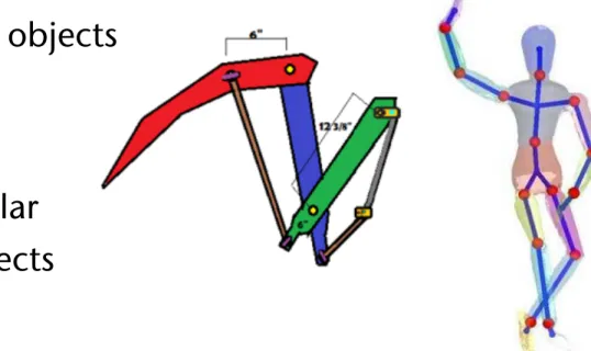
§ Very convenient for articulated objects
§ E.g., robots, skeletons, ..
§ Remark: 2D drawing programs (Photoshop et al.) create a similar hierarchy when you group objects
Figure 1:
Illustration of the part-finding process: (A),(a) a template mesh is registered to all other meshes by CC algorithm. (B) the mesh is divided into parts by clustering the estimated local transformations for each template point, different parts are color-coded. (b) the mesh is randomly divided into small patches of approximately equal areas, different parts are color-coded. (C),(c) results in (B),(b) are used to initialize the EM algorithm which solves for the part assignments and the transformation for each part. (D),(d) the joints linking the rigid parts are estimated.are not appropriate for recovering an articulated ob- ject skeleton: the notion of a joint between parts is not well-defined when each part consists of several disconnected regions. In order to model the object articulation correctly, we impose another kind of con- straint, which we call
hard contiguity constraint. Theconstraint specifies that a part can consist of no more than one connected component in the template mesh.
4.3 Model Summary
Ignoring the hard contiguity constraints, the frame- work described in Sec. 4 defines a
Markov networkover the part labels
α. A Markov network encodes the jointdistribution over a set of variables as a product of po- tentials:
P
(α) = 1
Z!
j
φ(αj
)
!j,k
φ(αj,αk
) (3) where
Zis a normalization constant.
The singleton potentials
φ(αj) correspond to the probabilities that a template point
xjgenerates its corresponding points
z1,j, . . . , zN,j, as follows:
φ(αj
=
p) =!N
i=1
P
(z
i,j | αj=
p, Ti,p) (4) The potential values depend on the transformations
Ti,p. Thus, the joint distribution depends on
T, the set of rigid part transformations. The pairwise po- tentials in the Markov network correspond to the soft contiguity constraints, and are defined in Eq. (2).
5 Optimization
We start with a template mesh
Xand instance meshes
Z , . . . , Z, and we need to solve for the set of part
We want to find a joint assignment to the part labels and the transformations which maximizes the log-likelihood of the model:
argmax
α,T
log
P(α, T ) = argmax
α,T { "
(j,k)∈E(X)
log
φ(αj,αk)
−−
1 2σ
2"n
i=1
"J
j=1
∥zi,j − Ti,αj
(x
j)
∥2}(5) where
Jis the number of points in meshes
X, Z1, . . . , ZN
. Note that our objective is defined as optimizing both the part assignment and transforma- tions simultaneously, rather than marginalizing over the (hidden) part assignment variables. A hard as- signment of points into parts is very appropriate for our application, and it also allows the use of efficient global optimization steps, as we discuss below. Note that the hard contiguity constraints are not accounted for in the above equation, and have to be enforced separately.
The objective in Eq. (5) is non-convex in the set of variables
α, T. We optimize it using hard
Expectation- Minimization (EM)to find a good assignment for
α, Tin an iterative fashion. EM iterates between two steps:
the
E-stepcalculates a hard assignment for all part labels
αgiven an estimate of the transformations
T. The
M-stepimproves the estimate for the parameters
Tusing the labels
αobtained in the E-step.
5.1 E-Step
Our goal in the E-step is to find the MAP assignment
to the part labels maximizing Eq. (5) for a given set of
transformations
T. It turns out that this is an instance
of the Uniform Labeling problem [17], which can be
expressed as an integer program. Following Kleinberg
Specialized Transform Nodes
§ Billboard:
§ Automatically computes a rotation, such that it's local z axis always points towards the viewpoint
§ Applies this transformation to the subtree underneath
§ Usage: fake complex geometry by
textured rendered on a single polygon (or a few)
§ Geometry has to be far away
The Behavior Graph
§ Animations and simulation eventually cause changes in the scene graph; e.g.:
§ Changes of transformations, i.e. the position of objects, e.g. of a robot arm
§ Modification of the materials, e.g. color or texture of an object
§ Deformation of an object, i.e. changes in the vertex coords
§ All these changes are equivalent to the change of a field of a node at
runtime
Events and Routes
§ The mechanism for changing the X3D/VRML scene graph:
§ Fields are connected to each other by so-called routes
§ A change of a field produces a so-called event
§ When an event occurs, the content of the field from the route-start is copied to the field of the route-end ("the event is propagated")
§ Other terminology: data flow paradigm / data flow graph
§ Used in most game engines today,
and in scientific visualization tools for a long time
§ Syntax of routes:
ROUTE Node1Name.outputFieldName TO Node2Name.inputFieldName
A simple example
DEF timer TimeSensor { loop TRUE
cycleInterval 5 }
DEF pi PositionInterpolator {
key [ 0 0.5 1 ] keyValue [ 0 -1 0, 0 1 0, 0 -1 0 ] }
DEF trf Transform { translation 0 0 0 children [
Shape { geometry Box { } } ]
}
ROUTE timer.fraction_changed TO pi.set_fraction ROUTE pi.value_changed TO trf.set_translation
example_route_bounce.wrl
Timer node
Inter- polator
Xform node
§ Routes connect nodes ⟶ behavior graph:
§ Is given by the set of all routes
§ A.k.a. route graph, or event graph (blueprint in Unreal engine)
§ Is a second graph, superimposed on the scenengraph
Example from Unreal
Digression: The AEO-concept
§ In X3D/VRML:
§ Actions & objects are all nodes in the same scene graph
§ Events are volatile and have no "tangible" representation
User
Actions Events
Objects
New Concepts for Data Flow in VR/Game Engines
§ Modern systems usually consist of many different components
§ Classic approach: fields-and-routes-based data flow
§ Problem: many-to-many connectivity
Procedural Content
Particle System AI
Input Devices Scene Graph
Physics
§ Quickly becomes inviable
Our Novel Approach: the Key-Value Pool
§ Assign a unique key to each route (link, connection)
§ Producer stores value with key in KV pool ⟶ KV pair
§ Corresponds to generating an event in the data flow paradigm
§ Consumer reads value from KV pair every time in its loop
§ Set of all KV pairs ⟶ KV pool
Procedural Content
Particle System AI
Input Devices Scene Graph
Physics
Key-value
pool
Advantages of the Approach
§ KV pool holds complete state of the virtual environment
§ Can save/load state, or unwind to earlier state
§ One-to-many connections are trivial
Classic Blocking Data Structures
§ One lock per KV pair, or one lock for the whole KV pool ⟶ both have disadvantages ⟶ in any case: lots of waiting
Procedural Content
Particle System AI
Input Devices Scene Graph
Physics
Key-value pool
Lock Access Unlock
Lock Access Unlock
Thread 1 Thread 2
Performance: Read (50%) & Write (50%) Operations
0 20 40 60 80 100 120 140 160
4 20 36 52 80 144 256 512
Ac ce ss t im e i n m s
Number of threads accessing the key-value pool
Our Approach
Lock-Based Approach Wait-Free Approach Optimistic Approach Filtered Approach
(KV Pool)
Demos
Cultural heritage
(Quelle: www.aqrazavi.org)
Education
Bsp.: sphere eversion Illustration of
complicated kinematics (hier: Schmidt Offset Coupling )
Would somebody be interested in implementing them on Unreal or
Javascript? (for Mac) Credits, credits J