Virtual Reality &
Physically-Based Simulation
Interaction Metaphors
G. Zachmann
University of Bremen, Germany
cgvr.cs.uni-bremen.de
The First(?) Interactive Computer Program
§ First really interactive, real-time computer game (arguably):
§ Spacewar, 1961, MIT
§ Two players, two spaceships ("wedge" and "needle"), each can fire torpedos
§ With it came the first real interaction devices and metaphors
A Classification of Interaction Tasks
§ Basic interaction tasks (BITs) in 2D GUIs [Foley / vanDam]:
§ Selection (objects, menus, ..)
§ Positioning (incl. orientation) or manipulation
§ Entering quantities (e.g., numbers)
§ Text input (via keyboard or speech input)
§ Universal Interaction Tasks (UITs) in VEs [Bowman]:
1. Navigation = change of viewpoint
2. Selection = define object or place for next task 3. Manipulation = grasp, move, manipulate object
4. System control = menus, widgets sliders, number entry, etc.
§ Model and modify geometry (very rare; not in Bowman's UITs)
More , Non-UIT Interaction Tasks
§ Search
§ E.g., searching a scene for a specific object, excluding the navigation
§ Ambient, implicit, playful, non-purposeful interaction
§ E.g., playing around with a virtual spraying can
§ Sculpting / modeling surfaces
§ Making an avatar dance by whole body interaction
Digression: Classification of Widgets for 3D UIs
Menu Selection
Temporary Option Menus Rotary Tool Chooser Menu Ball
Command & Control Cube Popup Menu
Tool Finger TULIP Single Menus
Ring menu Floating Menu Drop-Down-Menu Revolving Stage Chooser Widget
3D-Palette, Primitive Box etc.
Menu Hierarchies Hands-off Menu
Hierarchical Pop-Up Menus Tool Rack
3D Pie Menu
àHierarchy Visualizations Direct 3D Object Interaction
Object Selection
Geometric Manipulation 3D-Scene Manipulation
Orientation and Navigation Scene Presentation Control Exploration and Visualization
Geometric Exploration Hierarchy Visualization 3D Graph Visualization
2D-Data and Document Visualization Scientific Visualization
System / Application Control
State Control / Discrete Valuators Continuous Valuators
Special Value Input Menu Selection Containers
The Design of User Interfaces
§ There are two main approaches:
§ Natural interaction:
- Try to resemble reality and the interaction with it as closely as possible
§ "Magic" interaction
- Give the user new possibilities beyond reality
- Challenge: keep the cognitive overhead as low as possible, so that users don't get distracted from their task!
§
Tools:§ Direct user action (e.g., tracking of the body, gesture, head turning, ...)
- Pro: well suited if intuitive; con: possibilities are somewhat limited
§ Physical devices (e.g., steering wheel, button, ...)
- Pro: haptic feedback affords precise control
- Con: not easy to find/devise novel & useful devices
§ Virtual devices (e.g., menus, virtual sliders, etc., embedded in the VE)
- Pro: very flexible, reconfigurable, "anything goes"
§ Goals (in particular in VR):
1. Intuitive / natural interaction (usability)
- By definition: easy to learn
- Adjust to the user's expertise (expert vs. novice)
2. Efficient interaction (user performance)
- Precision, speed, productivity of the users
§ Problems (especially in VR):
§ No physical constraints (interaction in mid-air)
§ In particular: no haptic feedback
§ Efficient interaction with objects outside of the user's reach
§ Noise / jitter / imprecision in tracking data
§ Fatigue
§ No standards
There has never been a high performance task done in the history of this planet, to the best of my knowledge, that has ever been done well with an intuitive interface.
[Brian Ferran]
Pose Recognition
§ Is basically a simple classification problem:
§ Given: a flex vector = joint angles
§ Wanted: pose
§ Wanted: an algorithm that is ...
§ .. user independent
§ .. robust (> 99%)
§ .. Fast
§ General solution: machine learning algorithms (e.g, neural network) G (x ) 2 { “Fist“, “Hitch-hike“ , . . . }
x 2 R
d, d ⇡ 20
An Extremely Simple Pose Recognition Algorithm
§ Neural network is fine, if lots of gestures, or some of them are inside the parameter space
- However, experience shows: users can remember only a small set (e.g. 5)
§ Consider only a few poses near the border of parameter space
§ Discretize the flex vector
0 = flex value is "somewhere in the middle"
§ Pose = a region of d-dimensional parameter cube
§ Represent each region/pose by a discrete vector:
0 = don't care
§ Recognize f as pose i ⟺ f' "matches" gi
⟺
and ignore those f'[j] where g[j] = 0
Region of one gesture
8j : f 0[j] = g[j]
§ Implementation details:
§ Do automatic calibration at runtime to fill the range [0,1]:
- Maintain a running min/max and map it to [0,1]
- Over time, shrink min/max gradually (for robustness against outliers)
§ Ignore transitory gestures
§ Dynamic gestures =
1.Sequence of static poses/postures (e.g., sign language) 2.Path of a finger / hand
§ Utility for VR?
Navigation
§ Comprises: Wayfinding & Locomotion
§ Locomotion / Travel =
§ Cover a distance (in RL or in VR)
§ Maneuvering (= place viewpoint and/or viewing direction exactly)
§ Wayfinding =
§ Strategy to find a specific place (in an unknown building / terrain)
§ Comprises: experience, cognitive skills, ...
How do People Solve a Wayfinding Task
§ How do people find their way:
§ Natural hints/clues
§ Signs (man-made)
§ A simple user model for way finding:
§ In VEs, there can be two kinds of wayfinding aids:
§ Aids for improving the user's performance in the virtual environment
§ Aids that help increase the user's performance later in the real world
Which direction could bring me closer to my goal?
Travel some distance Where am I?
(possibly?) Creation of a mental map
§ Question: do humans create a mental map of their environment in order to solve wayfinding tasks?
§ Answer: probably yes, but not like a printed street map;
rather like a non-planar graph that stores edge lengths
http://www.spiegel.de/wissenschaft/technik/0,1518,739416,00.html
Kerstin Schill, Neuro-Informatics, Uni Bremen
Techniques for Navigation in VEs
§ A.k.a. "viewpoint control"
§ Real user navigation, e.g., walking, turning head, ...
§ Point-and-fly (especially in Caves and HMDs)
§ Walking in place
§ Scene-in-hand
§ World-in-Miniature
§ Orbital mode
§ And some more ...
A Taxonomy for this Interaction Task
§ Taxonomies are a technique to explore the design space of an interaction task!
Navigation
Specify
direction/target
Specify
speed/accel.
Condition that elicits navigation
Viewing direction Pointing direction Pointing in 2D
Constant
Gesture based Explicit
Automatic Incremental
Continuous mode Start/stop
Automatischer Start/Stop
Hand
Other object
Flex value Hand position
Speech Gesture Bicycle
Discretely Lists (Menus)
Objects in VE
Note on Interaction Task vs. Interaction Metaphor
Interaction Task Interaction
Devices Interaction Metaphor Define scaling on
tablet (e.g., for photo) Touch screen Pinch gesture Define position on
screen of desktop PC Mouse Move mouse on table, watch mouse pointer on screen, click Start a timer Hour glass Turn hour glass
Change gears in car Pedals and
gear stick First, push left pedal, move gear stick in desired position, release left pedal slowly
Switch room lights Microphone Clap hands three times
G. Zachmann Virtual Reality & Simulation WS 20 December 2017 Interaction Metaphors 31
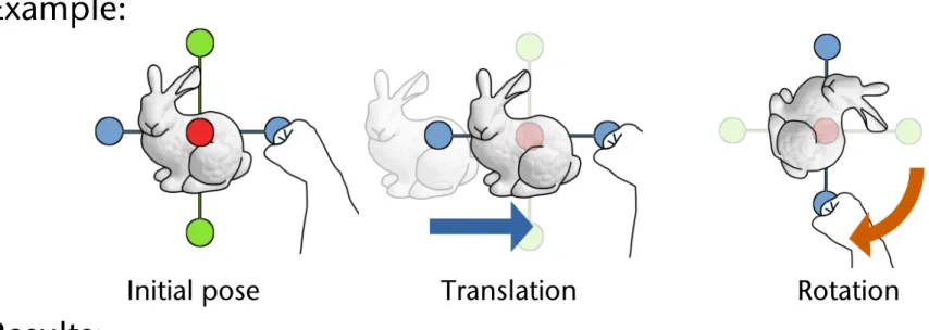
Interaction Design Principle: Separating DOFs
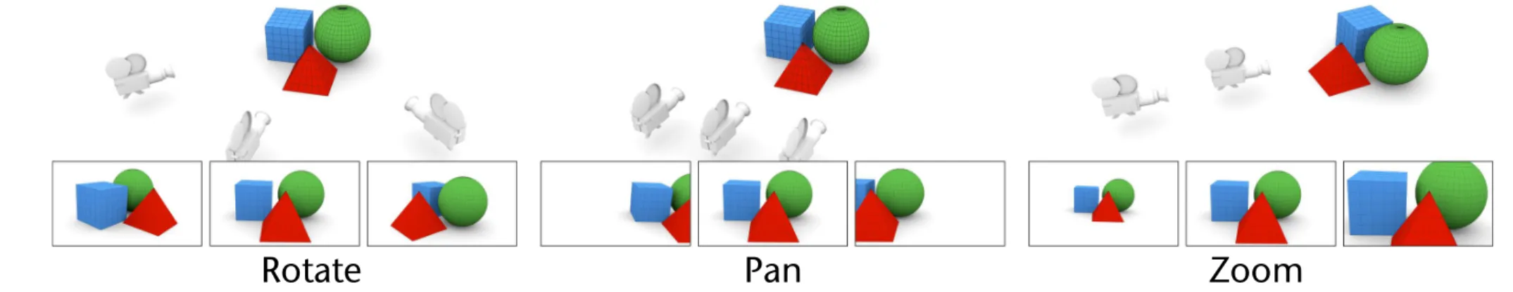
§ Here, by the example of the Rotate-Pan-Zoom technique (a.k.a. Rotate-Scale-Translate):
J. Jankowski & M. Hachet / A Survey of Interaction Techniques for Interactive 3D Environments
Figure 2:Rotating, panning, and zooming are the primary camera movements used in almost every 3D modelling environments.
2.1. General Movement (Exploration)
As we already mentioned, in an exploratory movement (such as walking through a simulation of an architectural design), the user does not have any specific goal. Its purpose is to rather gain knowledge of the environment. We classify it into the following groups:
2.1.1. Rotate-Pan-Zoom
Rotating, panning, and zooming are the primary camera movements used in almost every 3D modelling environ- ments (from Jack [PB88] to Autodesk’s 3ds Max, Maya, or Blender). They are standard ways to inspect objects, and work well with a pointing device such as a mouse since all of them are at most 2-dimensional operations.
• Rotate(also referred to asTumbleorSweep) - refers to or- biting the camera around a central point in any direction - the sweep operation sweeps the camera around horizon- tally and vertically on a virtual spherical track, keeping it focused at the same reference point (see Figure2(a)).
• Pan- in the context of 3D interaction,Panrefers to trans- lation of the camera along x and y axes (see Figure2(b));
• Zoom (also referred to as Dolly) - refers to translation of the camera along its line of sight (see Figure2(c)).
For example, to navigate in the viewport in Blender, the user needs to drag the mouse while holding the Middle Mouse Button (MMB) pressed to rotate, additionally pressing the Shift button on the keyboard to pan (Shift MMB), and hold- ing the Ctrl button to zoom (Ctrl MMB). It is worth to mention that some applications (including e.g., VRML/X3D viewers) additionally implementLook Aroundtechnique that changes the orientation of the camera but keeps it at a fixed position.
Current 3D rotation interaction techniques are generally based on the Chen et al.’s work on Virtual Sphere [CMS88]
and Shoemake’s ArcBall [Sho92], the techniques designed for 3D navigation around 3D objects. Both techniques are based on a concept of a virtual ball that contains the ob- ject to manipulate. They utilize the projection of the mouse location onto a sphere to calculate rotation axis and angle.
Comparison of mouse-based interaction techniques for 3D rotation can be found in [HTP⇤97,BRP05].
Rotate-Pan-Zoom technique requires the user to accom- plish a movement by shifting back and forth among simple navigation modes (assigning the mouse to "Rotate", "Pan", or "Zoom" operations) [PB88]. Such interaction model can be not optimal if the menu has to be used frequently. To solve this problem, Zeleznik and Forsberg [ZF99] proposed gestu- ral interaction for invoking camera functionality. Their ap- proach, called UniCam, requires only a single-button mouse to directly invoke specific camera operations within a sin- gle 3D view; remaining mouse buttons can be used for other application functionality.
Zeleznik et al. [ZFS97] explored a range of interaction techniques that use two hands to control two independent cursors to perform operations in 3D desktop applications.
The authors presented both how to navigate (Rotate-Pan- Zoom and flying techniques) and manipulate (Rotate-Scale- Translate) 3D objects using two pointer input. Balakrishnan and Kurtenbach [BK99] also investigated bimanual camera control; they explored the use of the non-dominant hand to control a virtual camera while the dominant hand performs other tasks in a virtual 3D scene.
2.1.2. Screen-Space Methods
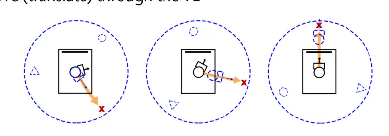
Gleicher and Witkin [GW92] describe a body of techniques for controlling the movement of a camera based on the screen-space projection of an object, where the user indi- cates the desired position of the object on the screen. In the other words, the presented through-the-lens techniques per- mit the user to control the virtual camera by directly manip- ulating the image as seen through the lens.
Inspired by Gleicher and Witkin’s work [GW92] and 3D navigation with multiple inputs [ZFS97,BK99], Reisman et al. [RDH09] describe a screen-space method for multi- touch 3D interaction. Just like 2D multi-touch interfaces al- low users to directly manipulate 2D contexts with two or more points, their method allow the user to directly manipu- late 3D objects with three or more points (see Figure3). The idea is that each contact point defines a constraint which en- sures the screen-space projection of the object-space point
"touched" always remains underneath the user’s fingertip.
Walther-Franks et al. [WFHM11] addressed the same prob- lem and designed and implemented multi-finger mappings
Rotate Pan Zoom
An Abstract Representation of the User
§ User = head, hand,
perhaps whole body (avatar)
§ The "flying carpet" metaphor :
§ User = camera
§ Camera is placed on a carpet / cart / wagon
§ Representation as (part of) a scenengraph:
rootcart
scaled cart
app.spec.
left hand
right hand camera
menus, heads-up infos, ...
rest of the world
The Point-and-Fly Metaphor
§
Controlling sensors:§ Head sensor → viewpoint
§ Hand sensor → moves cart:
s = speed,
t = direction, e.g., pointing direction of hand tracking sensor
§
Generalization: use graphical objects instead of sensor to derive translation direction (e.g., controller)§
Specification of the speed:§ Constant (e.g. with Boom)
§ Flexion of the thumb
§ Depending on distance |hand – body|
§ Make it independent of framerate slow normal fast
root
cart
rest of the world
viewpoint hand
M
Ct= M
Ct 1· Transl(s · t)
Perception of the Distance Travelled in VR
§ Question: how can the sense of presence be increased while navigating in a VE? (using point-and-fly)
§ Idea:
§ Make the viewpoint oscillate like in reality
§ (First-person-shooter games invented this earlier ;-) )
§ Results:
§ Only vertical oscillation helps increase presence
§ Users prefer slight oscillation over no oscillation
§ Short "travel distances" can be estimated more precisely (~ factor 2)
The Scene-in-Hand / Eyeball-in-Hand Metaphor
§ Scene-in-hand:
§ "Grabbing the air" technique
§ Cart remains stationary, scene gets rotated by hand sensor about a specific point in space
§ The transformation:
§ Instead of user's hand, use specific device, e.g. the CAT
§ Eyeball-in-hand:
§ Viewpoint is controlled directly by hand
§ Can be absolute or relative (accumulating) mode
root
cart
viewpoint hand root
cart
rest of the world viewpoint hand
MWt
M
Wt= M
Ht· (M
Ht0)
1· M
Wt0Two-Handed Navigation (a.k.a. 3D Multitouch)
§ Question: how to navigate with both hands?
§ Goals: increase input bandwidth, use simple input devices,
§ Idea: we only need 2 points and 1-2 triggers (→ pinch gloves)
§ Idea: use and modify "scene-in-hand" technique
§ 1 trigger, 1 moving point → translate the scene
§ 2 trigger, 1 fixed point , 1 moving point → rotate the scene
§ 2 trigger, 2 Punkte bewegt → scale the scene
§ Not well-established in VR (probably because pinch gloves have not prevailed)
§ But: is the standard today on handhelds! ;-)
§ Variation:
§ Direction = vector between both hands
SmartScene, MultiGen, Inc.
Real Walking on a Map
§ Idea: project a scaled down version
of the VE on the floor (map) and use feet
§ Coarse navigation: teleportation →
user walks to the new place/viewpoint on the map and triggers teleportation
§ System commands involved:
1.Bring up map = look at floor + trigger 2.Teleportation = look at floor + trigger 3.Dismiss map = look up + trigger
§ Trigger = speech command or "foot gesture"
§ Accurate navigation:
"lean" towards desired direction;
speed = leaning angle
Walking in Place (WIP)
§ The technique:
§ Head of user is tracked (optical tracker, or accelerometer) ⟶ time series
§ Classifier recognizes walking pattern in time series (and speed)
§ Cart is moved in gaze direction
§ Only forward direction is possible
§ Extension: TILT-WIP
§ WIP pattern just provides triggers
§ Tilting angle of head provides navigation direction (omnidirectional)
§ Can increase the level of subjective presence in the VE
§ Reason is probably that proprioceptive information from human body movements better matches sensory feedback from the computer-
generated displays
G. Zachmann Virtual Reality & Simulation WS 20 December 2017 Interaction Metaphors 41
Detecting the Walking Motion
§ Simple thresholding of
accelerometer data from head
§ Project acceleration onto vertical axis
§ Step := acceleration > threshold
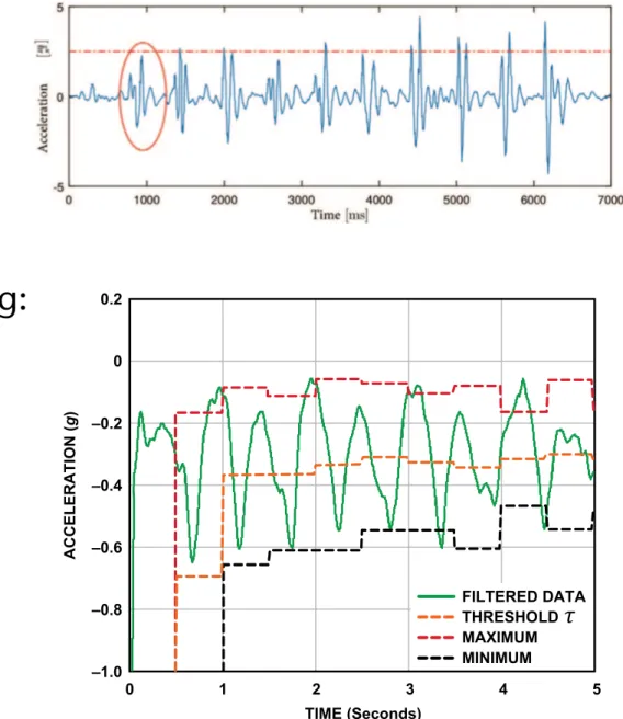
§ More sophisticated thresholding:
§ Every ½ second, calculate
min/max over last ½ sec of data
§ At the same time, calculate threshold ! = (max + min) / 2
§ With every new sample ai, check
step detected
Algorithm
Steps Parameter
Digital Filter: First, a digital filter is needed to smooth the signals shown in Figure 3. Four registers and a summing unit can be used, as shown in Figure 4. Of course, more registers could be used to make the acceleration data smoother, but the response time would be slower.
DATA0 DATA1 DATA2 DATA3
DATA IN
FILTER OUT
Figure 4. Digital filter.
Figure 5 demonstrates the filtered data from the most active axis of a pedometer worn by a walking person. The peak-to-peak value would be higher for a runner.
0.2
–1.0 –0.8 –0.6 –0.4 –0.2 0
0 1 2 3 4 5
ACCELERATION (g)
TIME (Seconds)
MINIMUM THRESHOLD MAXIMUM FILTERED DATA
Figure 5. Filtered data of the most active axis.
Dynamic Threshold and Dynamic Precision: The system continuously updates the maximum and minimum values of the 3-axis acceleration every 50 samples. The average value, (Max + Min)/2, is called the dynamic threshold level. For the following 50 samples,
this threshold level is used to decide whether steps have been taken. As it is updated every 50 samples, the threshold is dynamic.
This choice is adaptive and fast enough. In addition to dynamic threshold, dynamic precision is also used for further filtering as shown in Figure 6.
A linear-shift-register and the dynamic threshold are used to decide whether an effective step has been taken. The linear- shift-register contains two registers, a sample_new register and a sample_old register. The data in these are called sample_new and sample_old, respectively. When a new data sample comes, sample_new is shifted to the sample_old register unconditionally.
However, whether the sample_result will be shifted into the sample_new register depends on a condition: If the changes in acceleration are greater than a predefined precision, the newest sample result, sample_result, is shifted to the sample_new register;
otherwise the sample_new register will remain unchanged. The shift register group can thus remove the high-frequency noise and make the decision more precise.
A step is defined as happening if there is a negative slope of the acceleration plot (sample_new < sample_old) when the acceleration curve crosses below the dynamic threshold.
Peak Detection: The step counter calculates the steps from the x-axis, y-axis, or z-axis, depending on which axis’s acceleration change is the largest one. If the changes in acceleration are too small, the step counter will discard them.
The step counter can work well by using this algorithm, but sometimes it seems too sensitive. When the pedometer vibrates very rapidly or very slowly from a cause other than walking or running, the step counter will also take it as a step. Such invalid vibrations must be discarded in order to find the true rhythmic steps. Time window and count regulation are used to solve this problem.
Time window is used to discard the invalid vibrations. We assume that people can run as rapidly as five steps per second and walk as slowly as one step every two seconds. Thus, the interval between two valid steps is defined as being in the time window [0.2 s to 2.0 s]; all steps with intervals outside the time window should be discarded.
The ADXL345’s feature of user-selectable output data rate is helpful in implementing the time window. Table 1 shows the configurable data rate (and current consumption) at TA = 25íC, VS = 2.5 V, and VDD I/O = 1.8 V.
SAMPLE_RESULT SAMPLE_NEW SAMPLE_OLD
ACCELERATION CHANGES > PRECISION
ACCELERATION CHANGES < PRECISION
DECISION
DYNAMIC
THRESHOLD OUTPUT
STEP
Figure 6. Dynamic threshold and dynamic precision.
a
i< ⌧ ^ a
i 1> ⌧
!G. Zachmann Virtual Reality & Simulation WS 20 December 2017 Interaction Metaphors 42
§ Alternative to head tracking: track the user's heels
describe the shape of this distribution. Templeman and Sibert [14] described their speed curves as looking much like Figure 3(c) – claiming to achieve the smoothness and continuity that are also our goals for the LLCM-WIP system.
Of all of these locomotion systems Pointman is the only one that may be considered continuous, since it directly maps pedal movement to avatar/viewpoint movement. The other systems detect a pattern of motion of some part of the body and identify that pattern as a step. When a step is identified, the amount of motion corresponding to a step is applied. Thus each step is a discrete event, and the pattern-detection mechanism must necessarily wait until enough of a step motion has been performed by the user to unambiguously identify a step.
The Low-Latency, Continuous-Motion Walking-in-Place (LLCM- WIP) system – described in the remainder of this paper – improves on previous work in regard to lower latency and continuous motion. In LLCM-WIP, we consider user input as a continuous signal, not a series of discrete step events. In fact, LLCM-WIP has no concept of a step. It simply maps the speed of the heels to locomotion speed, employing minimal signal processing instead of pattern recognition. The result is a responsive system that produces smooth and realistic locomotion.
3 DESCRIPTION OF THE LOW-LATENCY,CONTINUOUS- MOTION WALKING-IN-PLACE SYSTEM
The implementation of LLCM-WIP is quite simple: It is a sequence of simple signal-processing operations on heel-tracking data. Section 3.1 gives an overview, and the following subsections describe the operations.
We developed LLCM-WIP to meet four important goals, each of which is fundamental to the experience of walking:
• Low latency
• Smooth locomotion between steps
• Continuous control of locomotion speed within each step
• Incorporation of real-world turning and short-distance maneuvering into virtual locomotion
We will point out how the components described in the following sub-sections, along with careful choice of their “tuning”
parameters, accomplish the above goals.
3.1 The System, in Brief
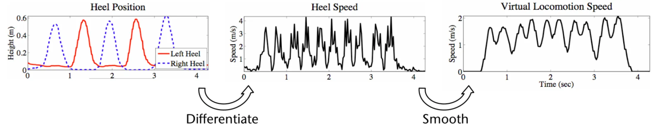
The LLCM-WIP system consists of the following stages. Note that stages 1-7 are performed on the two feet separately. Figure 3 shows the signal at several points in the process.
1. Track heel position
2. Isolate vertical component (z) 3. Numeric differentiation
4. Invert negative parts (absolute value) 5. Smoothing (low-pass filter)
6. Subtract a constant speed offset 7. Clamp negative values to zero
8. Combine (sum) signals from Left and Right feet 9. Scale to user-specific walking speed
10. Apply orientation (chest-direction with optional joystick) 11. Integrate locomotion velocity to get avatar-position offset 12. Sum avatar-position offset with real-world head position 13. Render viewpoint from combined virtual/real-world position
Figure 3: System overview. We track the vertical position of the user’s heels. Through numeric differentiation, we obtain the heel speed. After some signal processing operations, we have a virtual locomotion speed.
3.2 Vertical Speed of the Heels
Whereas previous systems focused on knee motion, we start with the vertical motion of the user’s heel. To obtain an estimate of the heel’s vertical speed, we track its position and perform numeric differentiation on the vertical component to yield vertical velocity.
We then invert the negative portions to yield a non-negative signal: the vertical heel-speed. Figure 3b shows the combined vertical heel-speed, summed over the left and right feet.
Because we employ a magnetic tracker and our lab floor is metal, we are unable to place trackers directly on the user’s feet due to unacceptable distortion in the reading. Instead, we place trackers on the shins, just below the knees, and perform a simple, rigid-body transform to estimate the user’s heel location. The offset from the shin-mounted tracker to the bottom of the heel is roughly fixed, regardless of the ankle pose. Even an approximate offset serves quite well: Instead of measuring each individual user’s shin length, we use the same (typical) value for all users.
The output of this stage is a pair of scalar signals: the vertical speed (a positive quantity) of the left and right heels. Sections 3.3 and 3.4 will explain how these signals are combined and mapped to locomotion speed.
A direct benefit of considering only the vertical component of the heel’s velocity is that real-world turning and short-range maneuvering can be distinguished from intentional virtual locomotion. For instance, nearly all natural, in-place turning involves vertical heel motions on the order of several centimeters or less, occurring at a speed that is much slower than that of actual locomotion steps. Users quickly learn to perform in-place turns and short, real-world steps with little vertical motion of the heels.
To prevent incidental vertical motions from producing unintended virtual locomotion (i.e. drift), we subtract a constant from heel speed, which effectively eliminates small or slow vertical motions of the heel (see section 3.3).
Numeric Differentiation
Smoothing, Offsetting, Scaling
describe the shape of this distribution. Templeman and Sibert [14] described their speed curves as looking much like Figure 3(c) – claiming to achieve the smoothness and continuity that are also our goals for the LLCM-WIP system.
Of all of these locomotion systems Pointman is the only one that may be considered continuous, since it directly maps pedal movement to avatar/viewpoint movement. The other systems detect a pattern of motion of some part of the body and identify that pattern as a step. When a step is identified, the amount of motion corresponding to a step is applied. Thus each step is a discrete event, and the pattern-detection mechanism must necessarily wait until enough of a step motion has been performed by the user to unambiguously identify a step.
The Low-Latency, Continuous-Motion Walking-in-Place (LLCM- WIP) system – described in the remainder of this paper – improves on previous work in regard to lower latency and continuous motion. In LLCM-WIP, we consider user input as a continuous signal, not a series of discrete step events. In fact, LLCM-WIP has no concept of a step. It simply maps the speed of the heels to locomotion speed, employing minimal signal processing instead of pattern recognition. The result is a responsive system that produces smooth and realistic locomotion.
3 DESCRIPTION OF THE LOW-LATENCY,CONTINUOUS- MOTION WALKING-IN-PLACE SYSTEM
The implementation of LLCM-WIP is quite simple: It is a sequence of simple signal-processing operations on heel-tracking data. Section 3.1 gives an overview, and the following subsections describe the operations.
We developed LLCM-WIP to meet four important goals, each of which is fundamental to the experience of walking:
• Low latency
• Smooth locomotion between steps
• Continuous control of locomotion speed within each step
• Incorporation of real-world turning and short-distance maneuvering into virtual locomotion
We will point out how the components described in the following sub-sections, along with careful choice of their “tuning”
parameters, accomplish the above goals.
3.1 The System, in Brief
The LLCM-WIP system consists of the following stages. Note that stages 1-7 are performed on the two feet separately. Figure 3 shows the signal at several points in the process.
1. Track heel position
2. Isolate vertical component (z) 3. Numeric differentiation
4. Invert negative parts (absolute value) 5. Smoothing (low-pass filter)
6. Subtract a constant speed offset 7. Clamp negative values to zero
8. Combine (sum) signals from Left and Right feet 9. Scale to user-specific walking speed
10. Apply orientation (chest-direction with optional joystick) 11. Integrate locomotion velocity to get avatar-position offset 12. Sum avatar-position offset with real-world head position 13. Render viewpoint from combined virtual/real-world position
Figure 3: System overview. We track the vertical position of the user’s heels. Through numeric differentiation, we obtain the heel speed. After some signal processing operations, we have a virtual locomotion speed.
3.2 Vertical Speed of the Heels
Whereas previous systems focused on knee motion, we start with the vertical motion of the user’s heel. To obtain an estimate of the heel’s vertical speed, we track its position and perform numeric differentiation on the vertical component to yield vertical velocity.
We then invert the negative portions to yield a non-negative signal: the vertical heel-speed. Figure 3b shows the combined vertical heel-speed, summed over the left and right feet.
Because we employ a magnetic tracker and our lab floor is metal, we are unable to place trackers directly on the user’s feet due to unacceptable distortion in the reading. Instead, we place trackers on the shins, just below the knees, and perform a simple, rigid-body transform to estimate the user’s heel location. The offset from the shin-mounted tracker to the bottom of the heel is roughly fixed, regardless of the ankle pose. Even an approximate offset serves quite well: Instead of measuring each individual user’s shin length, we use the same (typical) value for all users.
The output of this stage is a pair of scalar signals: the vertical speed (a positive quantity) of the left and right heels. Sections 3.3 and 3.4 will explain how these signals are combined and mapped to locomotion speed.
A direct benefit of considering only the vertical component of the heel’s velocity is that real-world turning and short-range maneuvering can be distinguished from intentional virtual locomotion. For instance, nearly all natural, in-place turning involves vertical heel motions on the order of several centimeters or less, occurring at a speed that is much slower than that of actual locomotion steps. Users quickly learn to perform in-place turns and short, real-world steps with little vertical motion of the heels.
To prevent incidental vertical motions from producing unintended virtual locomotion (i.e. drift), we subtract a constant from heel speed, which effectively eliminates small or slow vertical motions of the heel (see section 3.3).
Numeric Differentiation
Smoothing, Offsetting, Scaling
99
Authorized licensed use limited to: University of North Carolina at Chapel Hill. Downloaded on May 04,2010 at 14:43:40 UTC from IEEE Xplore. Restrictions apply.
Differentiate Smooth
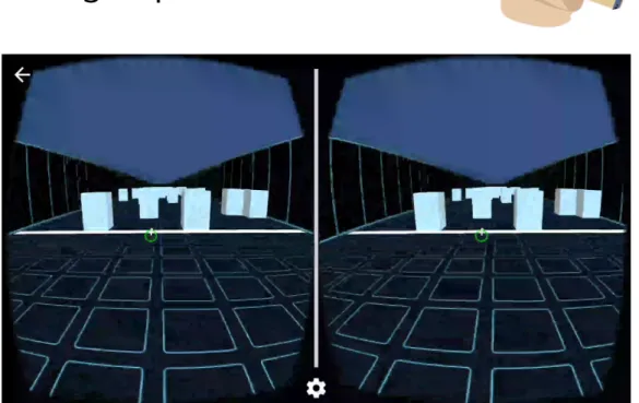
Example in Mobile VR
Eelke Folmer: VR-STEP
G. Zachmann Virtual Reality & Simulation WS 20 December 2017 Interaction Metaphors 44
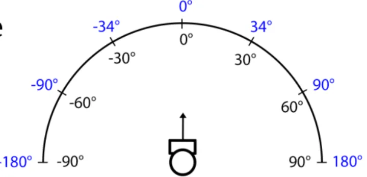
Head Tilt Based Navigation
§ Idea: angle between head's vertical axis and gravitational "up"
vector determines navigation speed (if bigger than threshold)
§ Project vector o onto XZ plane ⟶ navigation direction
§ Disadvantage: navigation cannot be uncoupled from gaze direction
§ Could be combined with walking-in-place
§ Walking = trigger , head tilt = direction
§ Allows for
omnidirectional navigation
(sideways, etc.)
BACKGROUND
Currently, controllers are most commonly used for VR naviga- tion, but because they don’t offer proprioceptive and vestibular feedback they provide low immersion [7] and carry a higher risk of inducing cybersickness [17]. Various virtual locomo- tion techniques exist, but because we focus on mobile VR contexts, we only survey methods that offer handsfree input.
WIP [25] is handsfree and as efficient as controller input [14];
but it is more immersive [26]; allows for better control over velocity [29]; and better spatial orientation [19]. Various WIP implementations are available but these rely on external cameras [25, 40, 28] or bulky hardware [39, 12, 6] which aren’t feasible to use in mobile VR contexts. VR-step [30] is a WIP implementation using inertial sensing that is available on mobile VR platforms, without any extra sensors. A user study with 18 subjects compared VR-step to an auto-walk technique and found no differences in performance or reliability, though VR-step was found to be more immersive and intuitive. A limitation of current WIP implementations is that they don’t support omnidirectional navigation.
Leaning interfaces offer handsfree omnidirectional VR naviga- tion and though they don’t stimulate proprioception like WIP, they maintain equilibrioception, which has found to be benefi- cial to immersion [37]. Laviola [20] explores leaning input to enable handsfree navigation in a 3D cave, but no comparative user studies were performed. ChairIO [4] embeds sensors in a single legged stool with a tilting spring mechanism to allow for 3 degrees of freedom (DOF) leaning input. Some results from user studies are reported, but it has been argued that seated leaning interfaces have limited immersion [22]. Both De Haan [13] and Valkov [32] explore the use of a low cost Wii balance board to enable 2 DOF leaning input for VR navi- gation. Though these approaches use low-cost commercially available hardware, no comparisons to other techniques are made.
Joyman [22] is a 2 DOF leaning interface inspired by a joystick.
It embeds an inertial sensor in a wooden board with metal handrails that is placed inside of a mini trampoline. When a user leans in a direction the board elastically tilts in the same direction. A user study with 16 participants compares Joyman to joystick input and found joysticks to be more efficient with no difference in error. Joyman was found to be more fun, more immersive and offer better rotation realism than joystick input.
Wang et al. [37] explores the use of a leaning based surfboard interface that offers 3 DOF leaning input. A user study with 24 subjects compares two different modes (isometric/elastic) and found the elastic mode to offer higher intuition, realism, presence and fun but was subject to greater fatigue and loss of balance. A follow up study evaluated frontal and sideways stance [36] and found a frontal stance is best.
Closely related are also the following approaches. Handsfree input is often required to make computers more accessible to users with severe motor impairments but who still retain dexterity of the head. Head tracking has been explored to let quadriplegics control a mouse pointer on the screen [5].
IMPLEMENTATION OF HEAD-TILT NAVIGATION
The implementation of head-tilt was largely inspired by the Joyman leaning interface [22], which imagines the user’s body to be a joystick. Our approach differs as we appropriate the head into a joystick. An upward vector~ois defined as pointing straight upwards (aligning with the negative gravity vector~g) when the user looks straight ahead. The anglea between~o and~gis defined as: a=~o•~gand is 0 when there is no tilt (see figure2). Because the user wears a smartphone on their head, both~oand~gcan be measured using its gyroscope.
Figure 2. defining head tilt us- ing vectors
Several tradeoffs should be considered when mapping head-tilt to virtual motion.
When using only head-tilt as input for navigation (TILT), we sacrifice some freedom of being able to look around.
Whena exceeds a predefined threshold pthe user’s avatar will move in the direction of vector~m, which is the projec- tion of~oonto the XZ plane.
Onceaexceeds thresholdp, immediate acceleration to a predefined velocityV might
cause cybersickness, certainly for lateral movements [35]. It might be better to gradually accelerate toV or interpolate the velocity between 0 and a valueqthat is reached for some max- imum value ofato allow for more precise navigation as users can control their velocity. The value chosen forpdetermines how much freedom a user still has to look around versus the amount of head tilt that needs to be provided for navigating.
This requires a careful tradeoff; requiring too much tilt is in- efficient and limits users’ ability to see where they are going where a low value ofpdoesn’t allow users to look up or down.
A previous study that analyzed free form navigation in VR [16] found that forward motion (47%) or forward+steering (37%) are the most frequently used inputs. Given these results, one could implement different values ofpdepending on what quadrant~m, lies, e.g., implement a small value forpfor for- ward tilt and larger values for the other directions as these are less likely to be used and users cannot see in those directions anyway.
To avoid this tradeoff altogether, looking around and triggering motion should be decoupled using a state transition. Given the limited input options of mobile VR we developed a solution that can enable this handsfree. When augmenting WIP with head-tilt (WIP-TILT), detected step input can act as a trigger for navigation, while still allowing users to look around when they do not walk.WIP-TILTis unique in that it combines the best of WIP and leaning interfaces, as it generates both proprioceptive and equilibratory feedback; which could potentially be most immersive.
Exploration of VEs using a Magic Mirror
§ Task/goal: present a second viewpoint (like inset in an image) intuitively in a VE, and allow for its manipulation
§ Idea: use the mirror as a metaphor → "magic mirror"
§ One object serves as hand mirror (could even look like it)
§ Keeps a fixed position relative to camera (follows head motions)
§ Can be manipulated like any other object in the VE
§ Additional features (not possible with real mirrors):
§ Zooming
§ Magnification / scaling down of image in mirror
§ Clipping of objects in front of mirror (which occlude mirror)
§ "Un-mirror" scene visible in mirror ("Richtig-herum-Drehen")
§ Switch between main viewpoint and mirror viewpoint
Optional
§ Examples:
§ Implementation:
§ Render scene 2x
§ First, render only into a small viewport (in the shape of the mirror) with
mirrored viewpoint
§ Save as texture
§ Second, render into complete viewport from main viewpoint
§ Third, render texture on top of mirror object (no z test)
§ Or, use method presented in Computer Graphics class
Optional
The Immersive Navidget – Example for Task Decomposition
§ Metaphor for defining the viewpoint directly
§ Input device: wand with wheels and buttons
§ Decomposition of the task:
1. Define the center of interest (COI)
- E.g. by ray casting: shoot ray into scene, intersection point = new COI
- Will be the center of a sphere
2. Define radius of sphere = distance of new viewpoint from COI
- Here: specified using wheel on wand
3. Define viewpoint on sphere (using ray) 4. Animate viewpoint on path towards new
viewpoint (= smooth teleportation)
§ Switch phases using a button on wand
Interlude: User Models
§ Idea: if we had a model of how users "work", then we could predict how they will interact with a specific UI and what their user performance will be
§ Advantage (theoretically): no user studies and no UI mock-ups necesary any more
§ Related fields: psychophysics, user interface design, usability
The Power Law of Practice
§ Describes, what time is needed to perform an activity after the n-th repetition:
T1 = time needed for first performance of the activity, Tn = time for n-th repetition,
a ≈ 0.2 ... 0.6
§ Warning:
§ Applies only to mechanical activities, e.g. :
- Using the mouse, typing on the keyboard
§ Does not apply to cognitive activities, e.g., learning for exams! ;-)
§ This effect, called learning effect, must be kept in mind when designing experiments!
T
n= T
1n
aHick's Law
§ Describes the time needed to make a 1-out-of-n selection, but there cannot be any cognitive workload involved:
, I
c≈ 150 msec where n = number of choices
§ Example: n buttons + n lights, one is lighted up randomly, user has to press corresponding button
§ Assumption: the distribution of the choices is uniform!
§ Warning: don't apply this law too blindly!
§ E.g., practice has a big influence on reaction time
§ Sometimes, Hick's law is taken as proof that one large menu is more time-efficient than several small submenus ("rule of large menus") … I argue this is — mathematically — correct only because of the "+1", for which there is no clear experimental evidence! Besides, there are many other factors involved in large menus (clarity, Fitts' law, …)
T = I
clog
2(n + 1)
Practice
Number of choices
Reaction time / sec
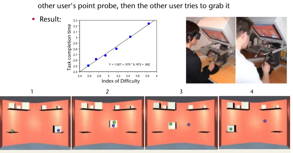
Fitts's Law
§ Describes the time needed to reach a target
§ Task: reach and hit a specific target as quickly and as precisely as possible with your hand/
pencil/ mouse/ etc., from a resting position
⟶ "target acquisition"
§ The law:
where D = distance between resting position and target, W = diameter of the target
§ The "index of difficulty" (ID) =
T = b log
2( D
W + 1) + a
log
2( D
+ 1)
Target Pointer
W D
Derivation of Fitts' Law
§ Assume a control loop muscle-eye-brain with
1. Constant processing power of brain
2. Inaccuracies of movement are proportional to target distance
§ Simplification: discretize control loop over time
§ Distance of pointer from target
§
,§ After n steps, the pointer is inside the target:
§ Solving for n yields
§ Each steps takes time !,
brain's "setup" time = a, overall:
D
0= D D
i= D
i 1=
iD
D
n=
nD < W
n = log (
WD)
Circle of error after first iteration
Circle of error
after second iteration Target Start
position
T = a + n⌧ = a + ⌧ log (
WD) = a + b log(
WD)
Demo / Experiment
§ Fitt's Law does apply directly to mouse movements required to
hit icons and buttons
Applications of Fitts' Law
§ "Rule of Target Size": The size of a button should be proportional to its expected frequency of use
§ Other consequences:
"Macintosh fans like to point out that Fitts's Law implies a very large advantage for Mac-style edge-of-screen menus with no
borders, because they effectively extend the depth of the target area off-screen. This prediction is verified by experiment.
"[Raymond & Landley: "The Art of Unix Usability", 2004]
§ Tear-off menus and context menus: they decrease the average travel distance D
§ Apple's "Dock": the size of the icons gets adjusted dynamically
1)
2)
3)
4) 1)
2)
3)
4) 1)
2)
3)
4) 1)
2)
3)
4)
§ Obvious limitations of Fitts's Law:
§ Fitts's Law cannot capture all aspects/widgets of a GUI
- E.g. moving target (like scrollable lists)
§ There are many other decisions with regards to the design of a UI that are contrary to an application of Fitts's law
Fun and instructive quiz on the homepage of this VR course: "A Quiz Designed to Give You Fitts"