Engineering a Highly Scalable
Object-aware Process Management Engine Using Distributed Microservices
Kevin Andrews, Sebastian Steinau, and Manfred Reichert Institute of Databases and Information Systems, Ulm University, Germany
{firstname.lastname}@uni-ulm.de
Abstract. Scalability of information systems has been a research topic for many years and is as relevant as ever with the dramatic increases in digitization of business processes and data. This also applies to process- aware information systems, most of which are currently incapable of scaling horizontally, i.e., over multiple servers. This paper presents the design science artifact that resulted from engineering a highly scalable process management system relying on the object-aware process man- agement paradigm. The latter allows for distributed process execution by conceptually encapsulating process logic and data into multiple in- teracting objects that may be processed concurrently. These objects, in turn, are represented by individual microservices at run-time, which can be hosted transparently across entire server clusters. We present mea- surement data that evaluates the scalability of the artifact on a compute cluster, demonstrating that the current prototypical implementation of the run-time engine can handle very large numbers of users and process instances concurrently in single-case mechanism experiments with large amounts of simulated user input. Finally, the development of scalable process execution engines will further the continued maturation of the data-centric business process management field.
1 Problem Definition
For decades, researchers have been examining parallelism, concurrency, and scal- ability in computer hard- and software. The topic of scalability also became instantly relevant to workflow management systems (WfMS) when they first showed up on the market, as they were explicitly built with large-scale appli- cations in mind [16]. First attempts to create scalable WfMS applied existing scalable architecture principles. The resulting approaches, such as WIDE [7], OSIRIS [17], ADEPTdistribution [5], and Gridflow [6], focused on the system ar- chitecture point of view, largely ignoring other aspects, such as role assignments, permissions, and data flow. However, the process models these approaches, espe- cially Gridflow, are meant to support, are typically high-performance production workflows, where these aspects merely play a secondary role [16].
Furthermore, with the increasing digitization of business processes and data in recent years, the scalability and speed of process management systems that fo- cus on the execution of human-centric processes has become a relevant topic.
This is most noticeable in the widespread availability of commercial cloud-based BPM solutions and even academic implementations [18]. Such cloud-based BPM solutions rely heavily on a highly scalable back end architecture to enable multi- tenancy without creating individual virtual machines for each customer. Cur- rently, however, no truly hyperscale process execution engine exists that com- bines a highly scalable back end with a process execution concept that allows more users to work on the same process instance than is possible in traditional, activity-centric process management, where the number of concurrently working users is typically limited by the branches in the process model [4].
This paper presents our in-depth experiences and details of the artifact that shall fill this gap: the PHILharmonicFlows process engine, which is implemented based on the object-aware process management paradigm [13]. Section 3 presents the solution objectives, detailing what we set out to achieve. Before delving into the artifact design and development in Section 4, we establish the necessary fun- damentals for object-aware process management in Section 2. The evaluation of the artifact can be found in Section 5. Section 6 gives a brief overview on related work. Finally, Section 7 summarizes the contribution and gives an outlook.
2 Fundamentals of Object-Aware Process Management
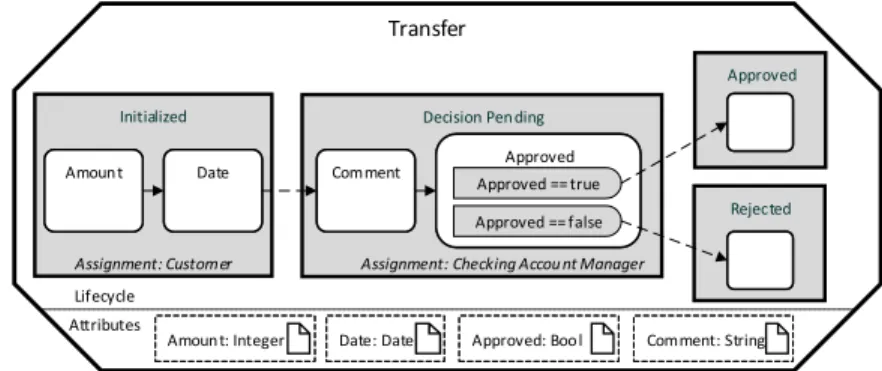
PHILharmonicFlows, the object-aware process management framework we are using as a test-bed for the concepts presented in this paper, has been under de- velopment for many years at Ulm University [4,13,20,3,14]. PHILharmonicFlows takes the idea of a data-driven and data-centric process management system, enhancing it with the concept of objects. One such object exists for each busi- ness object present in a real-world business process. As can be seen in Fig. 1, an object consists of data, in the form of attributes, and a state-based process model describing theobject lifecycle.
Amount: Integer Amount: Integer
Amount: Integer Date: DateDate: DateDate: Date Approved: BoolApproved: BoolApproved: Bool
Initialized Decision Pen ding
Approved
Rejected Amount
Amount DateDate ApprovedApproved
Comment: String Comment: String Comment: String Approved == true
Approved == false
Transfer
Lifecycle Attributes
Assignment: Customer Assignment: Checking Accou nt Manager Comment
Comment
Fig. 1.”Transfer” Object, with Lifecycle Process and Attributes
The attributes of the Transfer object (cf. Fig. 1) includeAmount, Date, Com- ment, andApproved. Thelifecycle process, in turn, describes the differentstates (Initialized, Decision Pending,Approved, andRejected), aTransfer object may pass during process execution. In turn, a state contains one or moresteps, each referencing exactly one of the object attributes, thereby forcing that attribute to be written at run-time. The steps are connected bytransitions, allowing them to be arranged in a sequence. The state of the object changes when all steps in a state are completed. Finally, alternative paths are supported in the form of decision steps, an example of which is theApproved decision step.
As PHILharmonicFlows is data-driven, the lifecycle process for the Transfer object can be understood as follows: The initial state of aTransfer object isIni- tialized. Once aCustomerhas entered data for theAmount andDateattributes, the state changes toDecision Pending, which allows anAccount Manager to in- put data forComment andApproved. Based on the value ofApproved, the state of theTransfer object changes to eitherApproved or Rejected. Obviously, this fine-grained approach to modeling business processes increases complexity com- pared to the activity-centric paradigm, where the minimum granularity of a user action is one atomic activity or task, instead of an individual data attribute.
Bank Transfer – Decision Bank Transfer – Decision
27.000 € 03.06.2017
true
Amount Date Approved*
Submit Comment
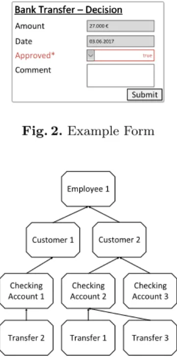
Fig. 2.Example Form Additionally, the object-aware approach allows for
automated form generation at run-time. This is facilitated by the lifecycle process of an object, which dictates the attributes to be filled out be- fore the object may switch to the next state, re- sulting in a personalized and dynamically created form. An example of such a form, derived from the lifecycle process in Fig. 1, is shown in Fig. 2.
Customer 1
Checking Account 1
Employee 1
Customer 2
Checking Account 2
Checking Account 3
Transfer 2 Transfer 1 Transfer 3
Fig. 3.Data Model Note that a single object and its resulting form
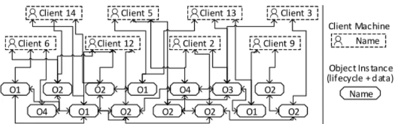
only constitutes one part of a PHILharmonicFlows process. To allow for complex executable business processes, many different objects may have to be involved [20]. The entire set of objects and rela- tions present in a PHILharmonicFlows process is denoted as the data model, an example of which can be seen in Fig. 3. In addition to the objects, the data model contains information about there- lations existing between them. A relation consti- tutes a logical association between two objects, e.g., a relation between aTransfer and aChecking Account. The resulting meta information, i.e., the information that theTransfer in question belongs to this specific Checking Account, can be used to coordinate the execution of the two objects.
Finally, complex object coordination, which is indispensable for processes with interacting business objects, is supported as well [20,19]. As objects publicly advertise their state information, the current state of an object is utilized as an
abstraction to coordinate with other objects through a set of constraints, defined in acoordination process. As an example, consider the following constraint: “Only 4Transfer objects that have a relation to the sameChecking Account may be in theApproved state at the same time”. A coordination process is always attached to one object, and can coordinate all objects related to that object.
In summary, objects each encapsulate data (i.e., theattributes) and logic (i.e., object behavior) which is based on attribute values (i.e., the lifecycle process).
Therefore, objects are largely independent of each other, apart from therelations that exist between them, which are necessary for their orchestration by the coordination processes.
3 Solution Objectives
The artifact we present in this work is the distributed object-aware process ex- ecution engine PHILharmonicFlows. As stated in the problem definition, there are two main objectives we wish to achieve with this artifact: develop a highly scalable process management system, which uses an underlying process manage- ment concept that allows for a multitude of users to work concurrently on the same process instance (i.e., Objective 1) and is engineered in a way so that it scales out well when more hardware resources are added (i.e., Objective 2).
Objective 1 can be achieved by breaking with the traditional activity-centric process management approach, i.e., employing an approach such as artifact- centric [8], case handling [1], or object-aware process management [14]. Due to the fact that in such approaches the tasks users have to perform are not shoehorned into atomic activities, such as forms, which only one person at a time can view and edit, they are intrinsically more scalable from a user point of view as more users may execute parts of process instances concurrently [4].
Objective 2, engineering the process engine in a way such that it becomes highly scalable in regards to the hardware it runs on, requires a more precise explana- tion. First, it is necessary to clarify that the goal is not to create a system that scales up well, i.e. vertically with a more powerful processor, but scales out well horizontally with more computers added to a data center or computing cluster, as this is generally more desirable in cloud scenarios. In particular, we aim at achievingideal linear speedup, i.e., increasing the amount of available processing power by factorp should speed up process execution byp [12].
Finally, while one can design an activity-centric process management engine in a way that allows it to scale well on the hardware side, the benefits of combining the necessary software architecture aspects with the conceptual aspects of object- aware process management are what make the artifact original.
4 Design and Development
The PHILharmonicFlows process engine has undergone many development cy- cles, starting with an extensive research phase concerning the conceptual foun-
dations (cf. Section 2). The most important architectural iteration concerned the scalability aspects described in this paper.
4.1 Architectural Challenges
Initially, we had opted for a relational database to hold the process execution state, as it is common in many other process engines. However, during the testing phase of the development iteration, we noticed that the prototype was plagued by severe scalability issues when confronting it with large numbers of concurrent users and objects. Note that, as opposed to more traditional (i.e., activity-centric) process management technology, object-aware process manage- ment needs to react to very fine-grained user actions. Due to the nature of the lifecycle processes and the dynamically generated forms, the engine has to react to each data element input by users at run-time. In consequence, there is a much higher frequency at which small workloads have to be completed by the process engine. Note that this is the price one has to pay for the increase in flexibility compared to activity-centric systems, which use predefined forms and allow for far fewer possible execution variants.
As mentioned, a relational database is not ideally suited as the backbone for such a data-centric and data-driven system, as each of the actions a user completes on one object may have effects on multiple other objects, each represented by rows in database tables. As a consequence, a large number of rows (for various attributes, objects, and relations) have to be loaded into memory to determine the effects of a user action. In particular, if actions lead to large amounts of small changes to other objects, time is wasted on locking/unlocking rows and tables, slowing the system down considerably. Furthermore, the necessary communica- tion between the individual objects is not predictable up front, as it depends on (1) the coordination process, (2) the structure of the data model, i.e., the relations that exist between the objects in question, and (3) the current state of each object. As these factors may change at any time during process execution, common techniques (e.g. relying on query optimization) are not ideal for our use case. In consequence, at least conceptually, object-aware process management has an unpredictable n-m-n communication pattern, a very simple depiction of which can be seen in Fig. 4. After carefully examining this unpredictable pattern we opted for a distributed approach to persisting the state of objects.
O2 O2
O2 O2 O2
O2 O2 O3
O4
O4 O1
O1 O1
Client 6
Client 6 Client 2Client 2 Client 9Client 9 Client 5
Client 5 Client 3Client 3
Client 12 Client 12
O1
Client 14
Client 14 Client 13Client 13
Name Name Client Machine
Name Object Ins tance (lifecycle + data)
Fig. 4.Object Communication Pattern (Simplified)
4.2 Design Methodology
After experimenting with highly distributed and lightweight document databases, such as RethinkDB and Couchbase, and not achieving satisfying performance results, we decided to not only distribute the persistence layer, but also the computation. To facilitate this, we appliedactor model theory.The actor model is a well established theoretical foundation for concurrency in parallel systems in which the computation and persistence layer are split into largely independent primitives calledactors [2]. Furthermore, it is supported by a number of frame- works for highly scalable applications and supports communication patterns such as the one present in object-aware process management (cf. Fig. 4).
Background on Actor Model Theory The following gives an overview on the theory behind theactor model. In essence, an actor consists of a message queue and a store for arbitrary data. The actor can receive messages and handle them using the data from its store or by sending messages to other actors. An actor, however, may only complete exactly one task at a time, i.e., an actor currently servicing a request from its message queue may only work on answering that one message, whereas all others are ignored until the current message is removed from the queue. An actor system usually consists of a very large number of actors of different types, which each type having different functionality which can be completed by any instances of that type.
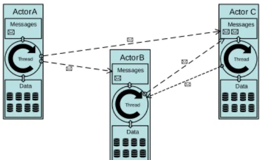
An example of the communication between a set of actors of different types, A, B, and C, can be seen in Fig. 5. Note that actor A receives a request from an external source, depicted by the message in its message queue. As each actor represents a small unit of functionality and data, an actor of type A might not have all the information or functionality to service the request, which necessitates communication with the other actors, e.g., B and C. However, the part of the request redirected at actor B triggers communication between Actor B and actor C. Due to the single conceptual “thread”, as well as the forced message queuing, most concurrency problems concerning persistence and computation, such as race conditions and dirty read/writes, cannot occur in an actor system.
Thread
Data ActorB Messages
Thread
Data Actor C Messages
Thread
Data ActorA Messages
Fig. 5.Actor Communication
Applying the Actor Model While the actor model may not be fitting for systems with few, yet long-running, tasks, it is well suited to handle the chal- lenges posed by a multitude of communicating and interacting objects present in an object-aware data model. While the actor model itself guarantees a highly scalable distributed system with few concurrency problems, the main challenge is to actually apply it to an existing concept or software system. In the context of our work, this means finding the correct mapping of the various conceptual elements of object-aware process management to individual actors. To this end, we elect to treat each object in a data model as an actor, which allows us to keep the conceptual elements contained in the object, i.e., the lifecycle process on the computation side, and the the attributes on the persistence side, together as one unit. Note that this ensures that updates to individual objects, such as changes to attribute values (and the resulting updates to the lifecycle processes), can be handled independently from unrelated objects.
Note that the coordination processes (cf. Section 2) coordinate the various ob- jects based on (1) their current state as well as (2) their relations to other objects.
To enable (1), objects that advance to a different state after one of their attribute values is changed must inform their coordination process of the respective state change. We facilitate this by leveraging the actor message pattern described in Section 4.2. To enable (2), we encapsulate the relations themselves as actors.
This allows the actor representing a new relation to send a message informing the coordination processes of its creation. Finally, to ensure that the coordina- tion processes handle such messages in the same way as objects, i.e., ordered and race condition free, we redesigned them to be actors as well.
Cluster Server Microservice Actor Model Conceptual
Element
Fig. 6. Encapsulation Dia- gram of Conceptual Elements, Actors, and Microservices To be precise, all high-level conceptual elements
present in object-aware processes, i.e., objects, relations, coordination processes, and the data model, are represented as actors in the PHILhar- monicFlows engine. As the actor model allows for independent execution of logic, using only well- regulated message exchanges at certain points, ac- tors can be hosted as individual microservices in computation environments. This results in a five layer concept for the process management engine, a sketch of which is shown in Fig. 6. As Fig. 6 im- plies, all high-level conceptual elements of object-
aware process management can be interpreted as actors, allowing them to be hosted in microservices on a server that can be part of a cluster. Clearly, Fig. 6 abstracts from the fact that multiple instances of any conceptual element may exist, resulting in one microservice per instance of the conceptual element exist- ing at run-time.
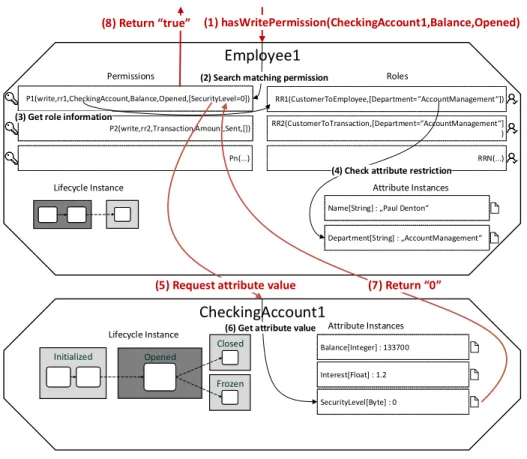
Note that we chose to keep the more fine-grained conceptual elements, such as attributes, permissions, roles, and lifecycle states and steps as state information inside the actors representing the objects. Taking the checking of an attribute
permission as an example, as shown in Fig. 7, it becomes evident why having the permissions and attributes as independent actors would make little sense.
Employee1
(1) hasWritePermission(CheckingAccount1,Balance,Opened)
P1(write,rr1,CheckingAccount,Balance,Opened,[SecurityLevel=0]) P1(write,rr1,CheckingAccount,Balance,Opened,[SecurityLevel=0]) P1(write,rr1,CheckingAccount,Balance,Opened,[SecurityLevel=0])
P2(write,rr2,Transaction,Amount,Sent,[]) P2(write,rr2,Transaction,Amount,Sent,[]) P2(write,rr2,Transaction,Amount,Sent,[])
Pn(...) Pn(...) Pn(...)
RR1(CustomerToEmployee,[Department=“AccountManagement“]) RR1(CustomerToEmployee,[Department=“AccountManagement“])
RR2(CustomerToTransaction,[Department=“AccountManagement“]
) RR2(CustomerToTransaction,[Department=“AccountManagement“]
) RRN(...) RRN(...)
Permissions Roles
Lifecycle Instance Attribute Instances
Department[String] : „AccountManagement“
Department[String] : „AccountManagement“
Department[String] : „AccountManagement“
Name[String] : „Paul Denton“
Name[String] : „Paul Denton“
Name[String] : „Paul Denton“
CheckingAccount1
Lifecycle Instance Attribute Instances
SecurityLevel[Byte] : 0 SecurityLevel[Byte] : 0 SecurityLevel[Byte] : 0 Balance[Integer] : 133700 Balance[Integer] : 133700 Balance[Integer] : 133700
Interest[Float] : 1.2 Interest[Float] : 1.2 Interest[Float] : 1.2
Initialized Opened
Closed
Frozen
(2) Search matching permission
(3) Get role information
(4) Check attribute restriction
(5) Request attribute value (8) Return “true”
(6) Get attribute value
(7) Return “0”
Fig. 7.Permission Request
In the example, two objects,Employee1 andCheckingAccount1, each represented by an actor at run-time, are shown. Note that only markings(1),(5),(7), and (8)constitute messages being passed between actors, all other markings are just operations that are completed using data local to the respective actor, the details of which are not relevant at this point, but can be found in previous work [3].
After the initial request(1) arrives in the message queue ofEmployee1, it has to complete a number of operations. Furthermore, this specific request causes theEmployee1 actor to communicate(5)with theCheckingAccount1 actor. In particular, granting the permission depends on the value of the SecurityLevel attribute, which is only present in the actor forCheckingAccount1. Finally, after actorCheckingAccount1 returns the value of the attribute(7), actorEmployee1 can return the result of the request(8).
Obviously, as the two actors for Employee1 andCheckingAccount1 may be lo- cated on different servers in the computing cluster, a request like this can in- troduce some communication overhead. However, as our goal is not to create an artifact that can resolve a single request to an object-aware process engine as fast as possible, but instead scales out well, this overhead is negligible, as shown by our measurement results in Section 5. A more fine-grained decomposition, e.g., putting every permission, attribute, and step of the lifecycle process into individual actors, would render no additional benefit as the information they represent is often only needed by the object they belong to.
In summary, we chose the actor model as a basis for the PHILharmonicFlows en- gine as it fits well to the already established conceptual elements of object-aware process management. Furthermore, as each actor maintains its own which solely this actor may access, we chose the granularity of decomposition of conceptual elements to actors in a way such that requests to an actor, e.g., an object, can be serviced without too much communication overhead. Moreover, having all data of an object located in the corresponding actor prevents common concur- rency problems, such as dirty reads on the attributes, as the data may only be accessed by one incoming request to the actor at the same time. Finally, the ar- chitecture, which is based on the actor model allows us to host each actor in its own microservice. As microservices enable high degrees of horizontal scalability, any computational logic that can be partitioned into individual actors can be scaled across multiple servers well. This means that scaling out the PHILhar- monicFlows engine horizontally is possible on the fly, which makes it ideal for scalable business process execution in cloud scenarios.
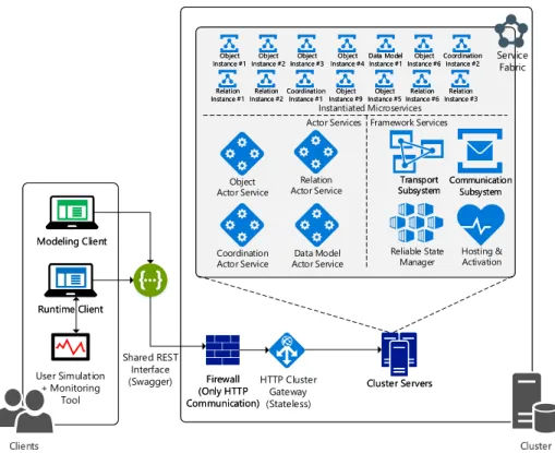
Architecture Several actor model based microservice frameworks exist, notable ones include Akka1(Java), CAF2(C++), and Orleans3(.NET). As the preexisting code base of PHILharmonicFlows was written in .NET, we utilize a modified version of Orleans, which is part of the open source Service Fabric Reliable Actors SDK4, for our prototype. Service Fabric allows us to run actor-based applications on development machines, on-premise research computing clusters, and in the cloud. This is enabled by a transparent placement of instantiated actors across all available servers. A diagram of the entire architecture of our engine is shown in Fig. 8. The “Actor Services” and “Framework Services” are hosted across all servers in the cluster, ensuring that they are all fully capable of instantiating actor microservices, such as those shown above “Instantiated Microservices”. All depicted elements are implemented and working to the specifications of object- aware process management. Finally, note that the engine is still only considered a prototype for our artifact, as we have not yet conducted technical action research with real-world clients.
1 https://github.com/akka
2 https://github.com/actor-framework
3 https://github.com/dotnet/orleans
4 https://github.com/Azure/service-fabric-services-and-actors-dotnet
Clients Clients
User Simulation + Monitoring
Tool
Cluster Cluster Modeling Client
Modeling Client
Runtime Client Runtime Client
Shared REST Interface
(Swagger) HTTP Cluster
Gateway (Stateless)
Cluster Servers Cluster Servers Firewall
(Only HTTP Communication)
Firewall (Only HTTP Communication)
Service Fabric
Hosting &
Activation Communication
Subsystem Communication
Subsystem Transport
SubsystemTransport Subsystem
Reliable State Manager Relation
Actor Service Object
Actor Service
Coordination
Actor Service Data Model Actor Service Object
Instance #1Object Instance #1 Object
Instance #2Object Instance #2 Object
Instance #3Object Instance #3 Object
Instance #4Object Instance #4Data Model
Instance #1 Data Model Instance #1 Object
Instance #6Object Instance #6Coordination
Instance #2 Coordination
Instance #2
Relation Instance #1Relation Instance #1 Relation
Instance #2Relation Instance #2Coordination
Instance #1 Coordination
Instance #1 Object Instance #9Object Instance #9 Object
Instance #5Object Instance #5 Relation
Instance #6Relation Instance #6 Relation
Instance #3Relation Instance #3 Instantiated Microservices
Actor Services Framework Services
Fig. 8.Architecture Overview
5 Evaluation and Demonstration
As other aspects of the PHILharmonicFlows process management system are still under development, both conceptually and from an implementation perspective, we have not completed technical action research to verify the solution objec- tives. Instead, we are currently conducing single-case mechanism experiments to evaluate the capabilities of the developed architecture, the results of which we present in this section. Before, however, we discuss conceptual performance limitations of object-aware processes as well as the measurement methodology.
5.1 Conceptual Performance Limitations
As each object in an object-aware data model can be interacted with individ- ually, there are hardly any bottlenecks to be expected for the execution of the object lifecycle processes. However, there is the issue of coordinating the exe- cution of inter-related objects that needs particular consideration. In general, coordination processes are informed by the objects when their states change due to the completion of steps in their lifecycle processes. How often this happens
depends on the lifecycle process model of the object in question. In particular, as these are merely fire-and-forget messages to the coordination process, they do not actually impact the performance of the object.
Obviously, coordination processes with constraints, such as the example given in Section 2, are necessary to model real-world processes. However, they do not con- stitute a scalability issue in the computing sense, as it is often necessary to wait for other parts of a process to complete in any process management paradigm. To enable such coordination constraints, it has to be clear which objects are linked to each other, i.e. have relations between them [19]. The structure of all objects and the relations between them constitute the data model of an object-aware process. As all relations are unidirectional and acyclic, the data model forms a tree-like directed acyclic graph structure, as shown in Fig. 3.
The central performance limitation of the artifact stems from the fact that link- ing a new object to the existing data model causes a recursive update all the way to the root object. This is necessary since any objects with coordination processes on higher levels of the data model have to be informed of new objects being attached on lower levels in order to coordinate them properly. To ensure that this operation is completed in an ordered fashion, it is completed by the actor representing the data model at run-time. As actors may only complete one action at a time, the linking of objects constitutes a performance bottleneck.
However, objects can only create relations to other objects as specified at design time in the process model. Thus, the number of relations creatable at run-time is directly limited by the business process itself. In summary, as in most cases objects are only related to one or two other objects directly (others transitively), only few relation creation operations are conducted for each object at run-time.
5.2 Experiment Scenario and Tooling
As our engine is an actor system running on Service Fabric (cf. Section 4.2), it can be deployed to a cluster with an arbitrary number of servers. For our single- case mechanism experiments, we employ an on-premise cluster with eight servers and a total of 64 logical processors (32 cores @ 2.4Ghz + hyper-threading). The data model used for the experiments is the Banking scenario presented in Section 2, an example of a typical object-aware process model.
Obviously, an object must be instantiated in a microservice before it can be linked to other objects or be manipulated through attribute value changes. How- ever, the order in which the attributes of an object are set, or whether they are set before or after linking the object to others, has no influence on outcome after all actions are completed. This is due to the fact that object-aware execution is data-driven, which allows us to design the experiment as follows: (1) we instan- tiate all objects required for the scenario a predefined number of times, (2) we link the objects together using a predefined schema, and, finally, (3) we supply predefined attribute values to each object we instantiated, thereby executing their lifecycle processes. Our tooling simulates user interaction directly through the run-time client via REST, using the architecture shown in Fig. 8.
We can measure times for all three action types, i.e., instantiation (1), linking (2), and execution (3), as well as the total time for a run. This allows us to discuss the three distinct actions and to observe the impact of changing various parameters on the time they take in relation to the total time.
5.3 Statistical Measurement Methodology
The measurements follow theguidelines for measuring the performance of par- allel computing systems, as defined in [12]. As a parallel computing system can render vastly different numbers for the same experiment scenario when run mul- tiple times, it is hard to measure exact execution times.
Instead of simply measuring the mean or median execution times over a prede- fined arbitrary number of runs, we use the statistically exact method presented in [12] to determine the number of runs necessary to ensure high confidence in an adequately small confidence interval. As we are dealing with non-normally distributed data, the number of runs has to be determined dynamically i.e., there is no analytical method for predetermining it. As it can take several hun- dred minute long runs to get a narrow confidence interval, this exact calculation becomes necessary to not waste hours trying to find an adequate number of runs.
To this end, we run Algorithm 1 after every individual experiment run to ensure that after n runs the confidence interval is tight enough and the confidence in the interval is high enough. The inputs are the already completed experiment runs (runs), the maximum width of the confidence interval as a percentage of the confidence interval average (%CI), and the minimum confidence in the confidence interval ((1−α)min). The algorithm returns interval[timelRank, timeuRank], i.e., the total time of the runs at the lower and upper bounds of the confidence interval, as well as(1−α), i.e., the exact confidence level of the returned interval.
Note that Algorithm 1 uses the statistical method described in [15], Annex A, to determine which of the already measured runs constitute the bounds of the confidence interval with the required confidence(1−α)min.
Algorithm 1checkCIWidth
Require: runs[],%CI,(1−α)min
Ensure: nruns≥6 .no confidence interval possible forn≤5
q←0.5 .quantile 0.5 = median
conf idenceLevels[]←[(lRank, uRank,(1−α)]
forj= 1tondo fork= 1tondo
conf idenceLevels←BinomialCDF(q, n, k−1)−BinomialCDF(q, n, j−1) end for
end for
for all(lRank, uRank,1−α)inconf idenceLevelsdo timelRank←runs[lRank].time
timeuRank←runs[uRank].time timemean←(timelRank+timeuRank)/2 CIwidthmax←timemean×%CI
iftimeuRank−timelRank≤CIwidthmaxand1−α≥(1−α)minthen return(timelRank, timeuRank,1−α)
end if end for
5.4 Results
We evaluated how well the artifact achieves the solution objectives (cf. Section 3) based on the measurement results from the single-case mechanism experiments presented in this section. The objective of the experiments was (1) to determine the limits of how many concurrent objects can be processes on the given eight server hardware setup, (2) find bottlenecks by simulating mass user interactions and (3) measure the impact of object lifecycle complexity on execution times.
To this end, we conducted the following series of single-case mechanism experi- ments with an example process model and simulated user input to the current PHILharmonicFlows engine prototype. While this is not technical action re- search in the real world, as explained in Section 5.2, the engine is interacted with exactly as if thousands of real users were executing the individual objects concurrently. We utilize these results to demonstrate the viability of a highly scalable actor model based microservice architecture for data-centric process management systems in general.
Each results table row represents an experiment series with a specific configura- tion and the following in- and outputs:
Header Description
Input
nD number of data models created
O object function, type and number of objects created per data model R relation function, A:B:100 indicates 100 relations between objects A and B
Output
nO number of created objects across all data models nR number of created relations across all data models CI tinst confidence interval for total instantiation time CI tlink confidence interval for total linking time
CI texec confidence interval for total lifecycle execution time CI ttotal confidence interval for total run time of experiment 1−α exact confidence in theCI ttotalconfidence interval
n number of runs completed to achieve1−αconfidence inCI ttotal
All confidence intervals in all result tables are required to have a maximum width of 5% in respect to the median measured time, i.e.,%CI= 0.05. Further, the confidence in each interval must be at least 95%, i.e., 1−αmin ≥ 0.95.
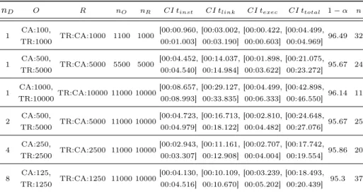
As this means that a measurement with a suspected median time of 1000ms is required to have a confidence interval of [975ms, 1025ms]5, and the confidence that the real median time lies in this interval must be at least 95%. Finally, all time measurements are specified in the mm:ss.ms format. Table 1 shows the measurement results for a scenario in which we instantiate, link, and execute varying numbers of Checking Accounts (CA) andTransfers (TR).
5 50ms width, 5% of 1000ms
Table 1.Simple Data Model: Checking Accounts (CA) and Transfers (TR) nD O R nO nR CI tinst CI tlink CI texec CI ttotal 1−α n
1 CA:100,
TR:1000 TR:CA:1000 1100 1000 [00:00.960, 00:01.003]
[00:03.002, 00:03.190]
[00:00.422, 00:00.603]
[00:04.499,
00:04.969] 96.49 32
1 CA:500,
TR:5000 TR:CA:5000 5500 5000 [00:04.452, 00:04.540]
[00:14.037, 00:14.984]
[00:01.898, 00:03.622]
[00:21.075,
00:23.272] 95.67 24
1 CA:1000,
TR:10000TR:CA:10000 11000 10000[00:08.657, 00:08.993]
[00:29.127, 00:33.835]
[00:04.499, 00:06.333]
[00:42.898,
00:46.550] 96.14 11
2 CA:500,
TR:5000 TR:CA:5000 11000 10000[00:04.723, 00:04.979]
[00:16.713, 00:18.122]
[00:02.810, 00:04.482]
[00:24.648,
00:27.076] 95.67 25
4 CA:250,
TR:2500 TR:CA:2500 11000 10000[00:02.943, 00:03.307]
[00:11.161, 00:12.908]
[00:02.707, 00:04.004]
[00:17.742,
00:19.554] 95.86 20
8 CA:125,
TR:1250 TR:CA:1250 11000 10000[00:04.130, 00:04.516]
[00:10.109, 00:10.670]
[00:03.239, 00:05.202]
[00:18.493,
00:20.439] 95.3 37
A few things are noteworthy here. First, regarding the first four series, in which all objects and relations were part of a single data model, one can observe almost ideal linear scaling of the various median times with the respective workloads, as evidenced by Fig 9. This demonstrates the capability of the microservices on the cluster to handle increasing concurrent workloads extremely well. Any below linear curve would indicate the system becoming congested.
Second, note the super-linear scaling of CI tlink in the four series with 10.000 relations spread over an increasing number of data models (cf. Fig. 10). This in- dicates a conceptual bottleneck due to the fact that the linking operations must be ordered to ensure correct recursive updating of the entire data model, as ex- plained in Section 5.1. To this end, each linking operation is queued and executed by the actor representing the data model in question, reducing concurrency.
0 5000 10000 15000 20000 25000 30000 35000 40000 45000 50000
0 1000 2000 3000 4000 5000 6000 7000 8000 9000 10000
MILLISECONDS
AMOUNT RELATIONS
Instantiation ms Linking ms Execution ms Total ms
Fig. 9.Single Data Model
0 5000 10000 15000 20000 25000 30000 35000 40000 45000 50000
1 2 3 4 5 6 7 8
MILLISECONDS
AMOUNT DATA MODELS Instantiation ms Linking ms Execution ms Total ms
Fig. 10.Multiple Data Models
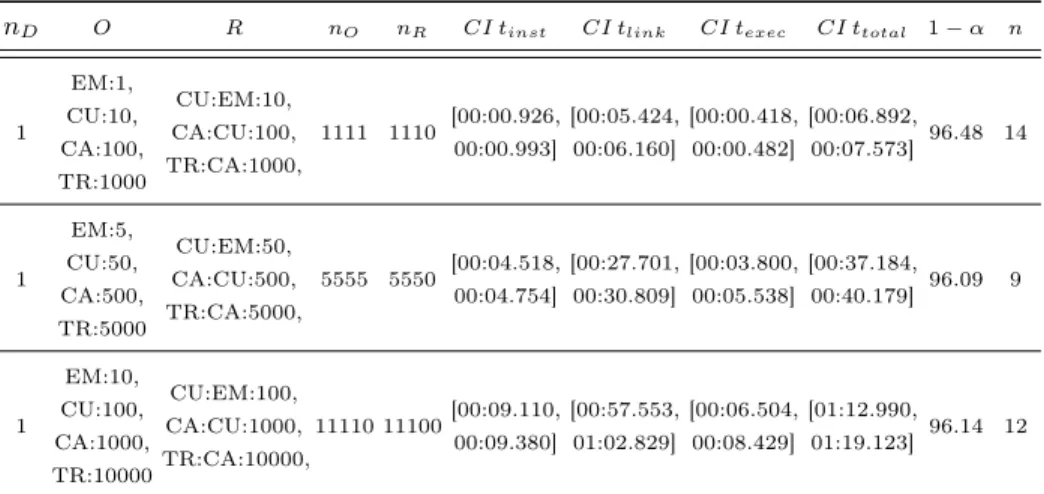
Table 2.Complex Data Model: Employees (EM), Customers (CU), Checking Accounts (CA), and Transfers (TR)
nD O R nO nR CI tinst CI tlink CI texec CI ttotal 1−α n
1
EM:1, CU:10, CA:100, TR:1000
CU:EM:10, CA:CU:100, TR:CA:1000,
1111 1110 [00:00.926, 00:00.993]
[00:05.424, 00:06.160]
[00:00.418, 00:00.482]
[00:06.892,
00:07.573] 96.48 14
1
EM:5, CU:50, CA:500, TR:5000
CU:EM:50, CA:CU:500, TR:CA:5000,
5555 5550 [00:04.518, 00:04.754]
[00:27.701, 00:30.809]
[00:03.800, 00:05.538]
[00:37.184,
00:40.179] 96.09 9
1
EM:10, CU:100, CA:1000, TR:10000
CU:EM:100, CA:CU:1000, TR:CA:10000,
11110 11100[00:09.110, 00:09.380]
[00:57.553, 01:02.829]
[00:06.504, 00:08.429]
[01:12.990,
01:19.123] 96.14 12
Table 2 shows the experiment results when creating a significantly more complex data model, with all objects and relations shown in Fig. 3. The objects involved are Checking Account (CA), Employee (EM), Transfer (TR), and Customer (CU). However, we adjusted the total amount of objects created to be almost identical to the experiment series shown in the first three rows of Table 1. Note the large increase in the CI ttotal interval when comparing Table 2 with Table 1. However, the increase clearly stems from the higher effort when linking new objects into the more complex data model, as evidenced by the higher CI tlink
values, as the averageCI tinstandCI texec values are similar.
Second, consider the wide CI texec intervals in comparison to the very tight CI tinstintervals (only theCI ttotal interval width is fixed at 5%). This can be explained with the fact that, while both instantiation and execution are tied to the complexity of the respective lifecycle process, instantiation is done by the actor service, while execution is done by the thousands of object actors created during instantiation and spread across the cluster. As we only have four actor services active during the experiment series shown in Table 2, the actor frame- work will distribute them to four distinct servers for each experiment run. As every server is equal, this leads to almost identical measured times across all ex- periments. However, as the underlying actor framework does not have knowledge of the varying complexity of the lifecycles processes in the different objects, the thousands of objects will also be distributed at random across the eight servers.
In consequence, as some objects take longer to execute their lifecycles than oth- ers, servers might be unequally tasked in this scenario, leading to comparatively wide confidence intervals.
Consider the following as a very simplified and extreme example of this effect:
objects of type A may take one second to execute their lifecycle process, whereas objects of type B may take ten seconds to execute their lifecycle process. If there
are two servers and ten objects of each type, in one experiment run both servers might be tasked with executing five objects of type A and five objects of type B, which would take 55 seconds in total. Another run might see all objects of type A executed by one server, taking ten seconds, and all objects of type B executed by the other server, taking 100 seconds.
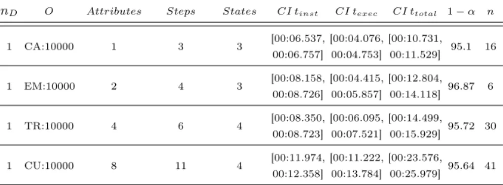
To further examine these differences in execution times , we instantiated and executed each object type used in Table 2 10.000 times. The results of this ex- periment can be seen in Table 3. As there are no relations in this experiment, we instead included the number of attributes, steps, and states the objects possess, as they give an indication as to how complex their lifecycle processes are. The results show the clear correlations between lifecycle complexity and instantia- tion/execution time.
Table 3. Comparison of Object Performance: Employees (EM), Customers (CU), Checking Accounts (CA), and Transfers (TR)
nD O Attributes Steps States CI tinst CI texec CI ttotal 1−α n
1 CA:10000 1 3 3 [00:06.537,
00:06.757]
[00:04.076, 00:04.753]
[00:10.731,
00:11.529] 95.1 16
1 EM:10000 2 4 3 [00:08.158,
00:08.726]
[00:04.415, 00:05.857]
[00:12.804,
00:14.118] 96.87 6
1 TR:10000 4 6 4 [00:08.350,
00:08.723]
[00:06.095, 00:07.521]
[00:14.499,
00:15.929] 95.72 30
1 CU:10000 8 11 4 [00:11.974,
00:12.358]
[00:11.222, 00:13.784]
[00:23.576,
00:25.979] 95.64 41
6 Related Work
There is a large amount of literature concerning the scalability of software sys- tems, little of which is concerned with process management systems. While the works mentioned in the introduction, WIDE [7], OSIRIS [17], ADEPTdistribu- tion [5], and Gridflow [6] are fairly dated and do not take modern architectures into consideration, there is some newer research that does.
[9] and [11] present architectures for distributing business process workloads between a client-side engine and a cloud-based engine, taking into consideration that users might not want to store their business data in the cloud. Thus, the approaches suggest to primarily run compute-intensive workloads on the cloud- based engine and transfer business data only when necessary. [9] further presents a method for decomposing the process model into two complementary process models, one for the client engine, and one for the cloud engine.
[10] introduces a resource controller for cloud environments that monitors pro- cess execution and can predict how compute intensive future workloads will be
depending on previous executions. This data is used for auto-scaling the virtual machines the process engine and external systems are running on.
[18] gives an in-depth overview of the state of the art concerning cloud business process architecture, revealing that most current approaches use virtual machine scaling, simply replicating process engines to achieve scalability.
7 Summary
In this work, we demonstrated the viability of creating ahyperscale process man- agement system using a data-centric approach to process management on the conceptual side as well as actor model theory and microservices on the archi- tecture side. Thus, we maximize the possible concurrent actions conducted by process participants at any given time during process execution, without simply relying on virtual machine scaling as most of the related work does. Our measure- ments show that the PHILharmonicFlows engine scales linearly with the number of objects created and executed (i.e., user-generated workload) in a single pro- cess instance. Furthermore, the measurements give insights into what the engine is capable of, with even this first prototype with no “professional” optimization executing the lifecycle processes of 11.000 objects in around five seconds. This is even more impressive considering the fact that these are full executions of the respective lifecycle processes. As the example objects have an average of 4-5 attributes and steps this equates to around 50.000 user interactions the engine is handling in the aforementioned five second time frame.
While the data from our single-case mechanism experiments shows that data- centric process engines have the potential to scale extremely well and to handle many users working on a single process instance at the same time, we identified a conceptual bottleneck in the linking of newly created objects to the existing data model. As this has to be handled centrally by the data model, it cannot be done concurrently. However, in a more real-world scenario with more running data models and less objects per data model, this is not much of an issue. This is especially true when considering that in general the ratio of object instantiations and linking to actual execution actions, such as form inputs by users, will be low.
In future work, we will work on optimizing the engine further and subjecting it to more real-world usage when conducing technical action research. Another important task is comparing the performance of PHILharmonicFlows to activity- centric process management systems, although finding a process scenario in which the two very different paradigms are scientifically comparable from a per- formance perspective will not be easy. Finally, as one of our stated goals is to increase the maturity and acceptance of data-centric process management, we are actively developing advanced capabilities, such as ad-hoc changes and variant support, on top of the presented artifact.
Acknowledgments.This work is part of the ZAFH Intralogistik, funded by the European Regional Development Fund and the Ministry of Science, Research and the Arts of Baden-Wï¿œrttemberg, Germany (F.No. 32-7545.24-17/3/1)
References
1. Van der Aalst, W.M.P., Weske, M., Grünbauer, D.: Case handling: a new paradigm for business process support. Data & Knowledge Engineering 53(2), 129–162 (2005) 2. Agha, G., Hewitt, C.: Concurrent programming using actors. In: Readings in Dis-
tributed Artificial Intelligence, pp. 398–407. Elsevier (1988)
3. Andrews, K., Steinau, S., Reichert, M.: Enabling fine-grained access control in object-aware process management systems. In: EDOC. pp. 143–152. IEEE (2017) 4. Andrews, K., Steinau, S., Reichert, M.: Towards hyperscale process management.
In: Proc EMISA. pp. 148–152 (2017)
5. Bauer, T., Reichert, M., Dadam, P.: Intra-subnet load balancing in distributed workflow management systems. Intl J of Coop Inf Sys 12(03), 295–323 (2003) 6. Cao, J., Jarvis, S.A., Saini, S., Nudd, G.R.: Gridflow: Workflow management for
grid computing. In: Intl Symp on Cluster Comp and the Grid. pp. 198–205 (2003) 7. Ceri, S., Grefen, P., Sanchez, G.: WIDE - a distributed architecture for workflow
management. In: RIDE-WS. pp. 76–79. IEEE (1997)
8. Cohn, D., Hull, R.: Business artifacts: A data-centric approach to modeling busi- ness operations and processes. Bulletin IEEE TCDE 32(3), 3–9 (2009)
9. Duipmans, E.F., Pires, L.F., da Silva Santos, L.O.B.: Towards a bpm cloud ar- chitecture with data and activity distribution. In: Enterprise Distributed Object Computing Conference Workshops (EDOCW), 2012 IEEE 16th International. pp.
165–171. IEEE (2012)
10. Euting, S., Janiesch, C., Fischer, R., Tai, S., Weber, I.: Scalable business process execution in the cloud. In: Cloud Engineering (IC2E), 2014 IEEE International Conference on. pp. 175–184. IEEE (2014)
11. Han, Y.B., Sun, J.Y., Wang, G.L., Li, H.F.: A cloud-based bpm architecture with user-end distribution of non-compute-intensive activities and sensitive data. Jour- nal of Computer Science and Technology 25(6), 1157–1167 (2010)
12. Hoefler, T., Belli, R.: Scientific benchmarking of parallel computing systems. In:
IEEE SC15. p. 73. ACM (2015)
13. Künzle, V., Reichert, M.: PHILharmonicFlows: towards a framework for object- aware process management. JSME 23(4), 205–244 (2011)
14. Künzle, V., Reichert, M.: Striving for object-aware process support: How existing approaches fit together. In: SIMPDA. pp. 169–188. Springer (2011)
15. Le Boudec, J.Y.: Performance evaluation of computer systems. Epfl Press (2010) 16. Leymann, F., Roller, D.: Production workflow: concepts and techniques. Prentice
Hall PTR Upper Saddle River (2000)
17. Schuler, C., Weber, R., Schuldt, H., Schek, H.J.: Scalable peer-to-peer process management - the osiris approach. In: IEEE ICWS. pp. 26–34 (2004)
18. Schulte, S., Janiesch, C., Venugopal, S., Weber, I., Hoenisch, P.: Elastic business process management. FGCS 46, 36–50 (2015)
19. Steinau, S., Andrews, K., Reichert, M.: The Relational Process Structure. In: 30th Int’l Conf. on Advanced Information Systems Engineering (CAiSE). pp. 53–67.
Springer (2018)
20. Steinau, S., Künzle, V., Andrews, K., Reichert, M.: Coordinating business processes using semantic relationships. In: Proc CBI. pp. 143–152 (2017)