in Object-aware Process Management
Sebastian Steinau, Kevin Andrews, and Manfred Reichert Institute of Databases and Information Systems, Ulm University, Germany
{sebastian.steinau,kevin.andrews,manfred.reichert}@uni-ulm.de
Abstract. Data-centric approaches to business process management, in general, no longer require specific activities to be executed in a certain order, but instead data values must be present in business objects for a successful process completion. While this holds the promise of more flex- ible processes, the addition of the data perspective results in increased complexity. Therefore, data-centric approaches must be able to cope with the increased complexity, while still fulfilling the promise of high process flexibility. Object-aware process management specifies business processes in terms of objects as well as their lifecycle processes. Lifecycle processes determine how an object acquires all necessary data values. As data val- ues are not always available in the order the lifecycle process of an object requires, the lifecycle process must be able to flexibly handle these devia- tions. Object-aware process management provides operational semantics with built-in flexible data acquisition, instead of tasking the process mod- eler with pre-specifying all execution variants. At the technical level, the flexible data acquisition is accomplished with process rules, which effi- ciently realize the operational semantics.
Keywords:lifecycle execution, data-centric processes, flexible data ac- quisition, process rules
1 Introduction
Data-centric modeling paradigms part with the activity-centric paradigm, and instead base process modeling and enactment on the acquisition and manip- ulation of business data. In general, a data-centric process no longer requires certain activities to be executed in a specific order for successful completion.
Instead certain data values must be present, regardless of the order in which they are acquired. Activities and decisions consequently rely on data conditions for enactment, e.g., an activity becomes executable once required data values are present. While this holds the promise of vastly more flexible processes in theory, it is no sure-fire success. The increased complexity from considering the data perspective in addition to the control-flow perspective requires a thoughtful design of any approach for modeling and enacting data-centric processes. This design should enable the flexibility of data-centric processes, while still being able to manage the increased complexity.
Object-aware process management [16] is a data-centric approach to busi- ness process support that aims to address this challenge. In the object-aware approach, business data is held in attributes. Attributes are grouped into ob- jects, which represent logical entities in real-world business processes, e.g., a loan application or a job offer. Each object has an associated lifecycle process that describes which attribute values need to be present for successfully process- ing the object. Lifecycle processes adopt a modeling concept that resembles an imperative style, i.e., the model specifies the default order in which attribute val- ues are required. Studies have indicated that imperative models show advantages concerning understandability compared to declarative models, which are known for flexibility [11, 20]. While the imperative style allows for an easy modeling of lifecycle processes, it seemingly subverts the flexibility promises of the data- centric paradigms, as imperative models tend to be rather rigid [25]. However, in object-aware process management, the operational semantics of lifecycle pro- cesses allow data to be entered at any point in time, while still ensuring correct process execution. The imperative model provides only the basic structure. This has the advantage that modelers need not concern themselves with modeling flexible processes, instead the flexibility is built into the operational semantics of lifecycle processes.
The functional specifications of the operational semantics of lifecycle pro- cesses have partially been presented in previous work [15]. This paper expands upon this work and contributes extended functionality and the technical im- plementation of the operational semantics, provided in the PHILharmonicFlows prototype. In particular, the logic involving execution events has been completely redesigned to include completion and invalidation events. These event types be- came necessary as otherwise the consistency of the lifecycle process was not guaranteed. Further, decision making in lifecycle processes has been improved by redesigning the data-driven operational semantics of decisions.
The technical implementation is based on theprocess rule framework, a light- weight, custom process rule engine. The framework is based on event-condition- action (ECA) rules, which enable reacting to every contingency the functional specification of the operational semantics permit, i.e., correct lifecycle process execution is ensured. The process rule framework will further provide the founda- tion for implementing the operational semantics of semantic relationships and coordination processes, the object-aware concept for coordinating objects and their lifecycle processes [23]. Such a coordination is necessary, as objects inter- act and thereby form large process structures, constituting an overall business process [22]. As such, coordination processes enable collaborations of concur- rently running lifecycle processes, having the advantage of separating lifecycle process logic and coordination logic. With the transition of PHILharmonicFlows to a hyperscale architecture [2], the process rule framework is fully compatible with the use of microservices, enabling a highly concurrent execution of multiple lifecycle processes with large numbers of user interactions.
The remainder of the paper is organized as follows: Section 2 provides the fundamentals of object-aware process management. In Section 3, the extended
operational semantics are presented. The process rule framework at the core of the operational semantics implementation is described in Section 4. Finally, Section 5 discusses related work, whereas Section 6 concludes the paper with a summary and an outlook.
2 Fundamentals
Object-aware process management organizes business data in form of objects, which comprise attributes and a lifecycle process describing object behavior.
PHILharmonicFlows is the implementation of the object-aware concept to pro- cess management. Object-aware process management distinguishes design-time entities, denoted as types (formally T), and run-time entities, denoted as in- stances (formally I). Collectively, they are referred to as entities. At run-time, types may be instantiated to create one or more corresponding instances. For the purposes of this paper, object instance (cf. Definition 1) and lifecycle process instance (cf. Definition 2) definitions are required. The corresponding type defi- nitions can be found in [16]. The “dot” notation is used to describe paths, e.g., for accessing the name of an object instance.⊥describes the undefined value.
Definition 1. (Object Instance)
An object instance ωIhas the form (ωT, n, ΦI, θI)where
– ωT refers to the object type from which this object instance has been gener- ated.
– nis the name of the object instance.
– ΦI is a set of attribute instances φI, where φI = (n, κ,vκ), with n as the attribute instance name,κas the data type (e.g., String, Boolean, Integer), andvκ as the typed value of the attribute instance.
– θI is the lifecycle process (cf. Definition 2) describing object behavior.
An object’s lifecycle process (cf. Definition 2) is responsible for acquiring data values for the attributes of the object.
Definition 2. (Lifecycle Process Instance)
A lifecycle process instance θI has the form (ωI, ΣI, ΓI, TI, ΨI, Eθ, µθ) where
– ωI refers to the object instance to which this lifecycle process belongs.
– ΣI is a set ofstate instancesσI, withσI = (n, ΓσI, TσI, ΨσI, µσ)where
• nis the state name.
• ΓσI ⊂ΓI is subset of stepsγI.
• TσI ⊂TI is a subset of transitionsτI.
• ΨσI ⊂ΨI is a subset of backwards transitionsψI.
• µσ is the state marking.
– ΓI is a set of step instancesγI, withγI = (φI, σI, TinI , ToutI , PI, λ, µγ, dγ) where
• φI ∈ωI.ΦI is an optional reference to an attribute instanceφI fromΦI of object instanceωI. Default is ⊥.
If φI =⊥, the step is denoted as an empty step instance.
• σI ∈ΣI is the state instance to which this step instanceγI belongs.
• TinI ⊂TσI is the set of incoming transition instances τinI.
• ToutI ⊂TσI is the set of outgoing transition instances τoutI .
• PI is a set of predicate step instances ρI, PI may be empty, with ρI = (γI, λ)where
∗ γI is a step instance.
∗ λis an expression representing a decision option.
If PI 6=∅, the step instanceγI is called a decision step instance.
• λis an optional expression representing a computation.
Ifλ6=⊥, the step instanceγI is called acomputation step instance.
• µγ is the step marking, indicating the execution status ofγI.
• dγ is the step data marking, indicating the status ofφI.
– TI is a set oftransition instancesτI, withτI = (γsourceI , γItarget,ext, p, µτ) where
• γsourceI ∈Γ is the source step instance.
• γtargetI ∈Γ is the target step instance.
• ext :=γsourceI .σI =γtargetI .σI is a computed property, denoting the tran- sition as external, i.e., it connects steps in different states.
• pis an integer signifying the priority of the transition.
• µτ is the transition marking.
– ΨI is a set ofbackwards transition instancesψI,ΨI may be empty, with ψI = (σIsource, σtargetI , µψ)where
• σsourceI ∈ΣI is the source state instance.
• σtargetI ∈ΣI is the target state instance,σtargetI ∈Predecessors(σsourceI ).
• µψ is the backwards transition marking.
– Eθ is the event storage forθI, storing execution eventsE. – µθ is the lifecycle process marking.
All sets are finite and must not be empty unless specified otherwise. The function Predecessors: σI → ΣI determines a set of states from which σI is reachable.
The function Successorsis defined analogously.
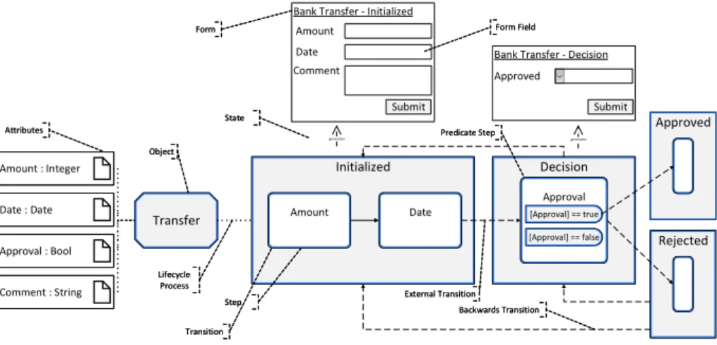
Note that for the sake of brevity the value of a stepγI refers to the value of the corresponding attribute γI.φI. Furthermore, correctness criteria have been omitted from Definitions 1 and 2. For the sake of clarity, a lifecycle process is described by a directed acyclic graph with one start state and at least one end state. Figure 1 shows object instanceBank Transfer with its attributes and lifecycle process. The object instance represents a simplified transfer of money from one account to another. For this purpose, the states and the steps of a lifecycle process can be used toautomatically generate forms. This is unique for process management systems, as in other systems, forms must still be designed manually, leading to a huge difference regarding productivity [25]. Additionally, when executing a process, the auto-generated forms are filled in by authorized users. The PHILharmonicFlows authorization system and its connection to form
auto-generation has been discussed in [1]. In essence, forms may be personalized automatically based on the user’s permissions, no different form designs showing different form fields are necessary.
Bank Transfer - Decision Bank Transfer - Initialized
Rejected Rejected Approved Approved Decision
Decision Initialized
Initialized Amount : Integer
Amount : Integer Amount : Integer
Date : Date Date : Date Date : Date
Approval : Bool Approval : Bool Approval : Bool
Comment : String Comment : String Comment : String
Object Object Attributes
Attributes
Lifecycle Process Lifecycle Process
State State
Step Step
Predicate Step Predicate Step
Backwards Transition Backwards Transition Transition
Transition
Amount Date
Submit
Comment Approved
generates generates
Submit Form
Form Form FieldForm Field
External Transition External Transition
Transfer
Transfer AmountAmount DateDate
Approval [Approval] == true [Approval] == true [Approval] == false [Approval] == false Approval [Approval] == true [Approval] == false
Fig. 1.Example object and lifecycle process of a Transfer
As depicted in Figure 1, the state σIInitialized contains steps γAmountI and γDateI , signifying that values for attributesφIAmountandφIDateare required during process execution. For the sake of brevity, the properties of an entity (e.g., the name of a step γ) may be written as a subscript, e.g., γAmount for the first step in Figure 1. The form corresponding toσInitializedI contains input fields for stepsγAmountI andγIDate. This means a state represents a form, whereas the steps represent form fields. TheφICommentfield is an optional field visible to a user due to the authorization system of PHILharmonicFlows. In stateσDecisionI , a decision stepγApprovalI represents the approval of the bank for the money transfer. The automatically generated form displaysγApprovalI as a drop-down field. End states σIApprovedandσIRejecteddisplay an empty form, as the contained steps are empty (cf. Definition 2). Transitions determine at run-time which attribute value is required next, an external transition also determines the next state. Backwards transitions allow returning to a previous state, e.g., to correct a data value.
3 Lifecycle Process Operational Semantics
Data acquisition in PHILharmonicFlows is achieved through forms, which can be auto-generated from lifecycle process modelsθI. A form itself is mapped to a stateσI of the lifecycle processθI; form fields are mapped to stepsγI. In conse- quence, the operational semantics of lifecycle processes emulate the behavior of electronic and paper-based forms, following a “best of both worlds” approach.
Paper-based forms provide a great overview over the form fields, i.e., every form field may be viewed at any point in time. Further, they provide a reasonable de- fault structure, but allow filling form fields at any point in time and in any order, e.g., starting to fill in form fields in the middle of the form is possible. In turn, electronic forms usually provide less overview, i.e., viewing subsequent forms is not possible before having filled out all mandatory fields in the current form. In contrast to paper-based forms, however, electronic forms are able to only dis- play relevant fields, especially in context of decision branching. For example, an electronic anamnesis form at a physician’s office may skip the questions related to pregnancy entirely if the patient is male. Additionally, electronic forms allow for data values to be easily changed as well as for data input verification, e.g., ensuring that a date has the correct format or all mandatory form fields possess a value. PHILharmonicFlows combines the advantages of both paper-based and electronic forms, providing flexibility in entering data while ensuring a correct lifecycle process execution.
3.1 Lifecycle Process Execution
For realizing the combined benefits, the progress of a lifecycle process θI is determined by its active state σIA , i.e., marking σI.µσ =Activated. Only one stateσI ofθI may be active at any point in time. Per default, the form of the active state is displayed to a user when executing lifecycle processθI. However, the user may choose to display forms of other states. When processing θI, the active state changes, depending on data availability and decision results. For example, in regard to Figure 1, starting the execution of the lifecycle process activates σIInitialized. If values for steps γIAmount and γDateI are available (cf.
Section 3.2),σInitializedI may be marked asµσ=Confirmed, and the next state σIDecisionbecomes active, i.e.,σIDecision.µσ=Activated. Depending on the value ofγApprovalI , eitherσApprovedI orσIRejectedbecomes active. As both states are end states, the execution ofθI terminates. The active state possesses a crucial role in the execution of θI, as consequences from data acquisition or decisions are only evaluated for the active state. For example, providing value true to γApprovalI does not trigger the decision, if σIInitialized is the currently active state. This is to avoid inconsistent processing states, e.g., because a previous decision may make filling out a stateσI obsolete due to dead-path elimination [16].
For several reasons, including automatic form generation and process lifecycle coordination, only exactly one state may be active at a given point in time. If two or more state had become simultaneously active, it would be unclear which form should be presented to the user, or what the progress of the lifecycle is. State execution (cf. Section 3.2) must therefore enforce that only exactly one state may activate at the conclusion of a previous one. In consequence, the enabling of external transitions must be mutually exclusive. Regarding decisions steps and its predicate steps, additional measures are required to prevent the simultaneous enabling of different transitions.
For statesSuccessors(σIA), data values may be entered, but processing only occurs once a state becomes active. All successor states possess marking µσ =
Waiting. If a user enters values for steps γI, these values will be stored and taken into account if the corresponding stateγI.σI becomes active. To indicate the status of the corresponding attribute value, steps possess adata marking dγ. When setting the data value for a stepγhasV alueI , where the state instanceσI has µσ=Waiting, the data marking ofγhasV alueI is set todγ =Preallocated. Should σI become active during process execution,dγ =Preallocated will indicate that a value is present and thus is not be required anymore (cf. Section 3.2).
States that have already been processed, i.e., P redecessors(σIA), will ei- ther have marking µσ = Confirmed or µσ = Skipped. States with marking µσ=Confirmed have previously been active, whereas skipped states have under- gone a dead-path elimination. For reasons of data integrity, the values of steps in skipped or confirmed states must not be altered at any point in time. If allowed, inconsistencies and unpredictable execution behavior may occur. For example, changing values of decisions steps in an uncontrolled way might activate currently eliminated states, whereas currently active states become eliminated. However, it must be possible to correct mistakes for previously entered and accidentally confirmed data. Therefore,backwards transitions(cf. Definition 2) allow for the reactivation of confirmed states in a controlled way, where the data may be al- tered in a consistent and safe way; consequently, subsequent changes in decisions can be handled properly. The reactivation of states and correction of mistakes contributes much to the flexibility of object-aware lifecycle process execution.
3.2 State Execution
While PHILharmonicFlows is capable of auto-generating forms from states and steps, so far, these forms are static. However, there are dynamic aspects to a form, e.g., the indication which value is required next or which external transition or backwards transition may be committed. For this purpose, a lifecycle processθI providesexecution events E and anevent storageEθ. Execution events are dy- namically created when processing a lifecycle processθI. When auto-generating a form, the static form is enriched with dynamic information from Eθ and dis- played to the user. Execution events have different subtypes, namely request events, completion events,andinvalidation events. When request events are cre- ated, they are stored in Eθ and are then used to enrich the form. Completion and invalidation events remove request events fromEθ, when a request event are either fulfilled or no longer valid, respectively. The usage of the event storageEθ, in conjunction with the generated static forms, allows multiple users access to the same form, due to the centralized storage of the dynamic form data. The use ofEθ further allows preserving dynamic data over multiple sessions, i.e., a user may partially fill out a form, close it and do something else, and later return and continue where the user previously stopped. It is even possible that another user finishes filling out the form, introducing additional flexibility. In general, storing execution eventsE ensures consistency regardless of any user interaction with the forms.
The creation and removal of execution events is primarily determined by the respective markingµof states, steps, transitions, and backwards transitions. For
steps with an attribute (i.e.,γI.φI 6=⊥), data marking dγ is also taken into ac- count. For example, if stepγAmountI in Figure 1 has markingµγ =Enabled, but γAmountI .dγ = Unassigned holds, an “attribute value request” event is created and stored in Eθ after some intermediate processing steps. If a user accesses the form for σInitializedI , the form field for γIAmount is tagged with an asterisk, indicating that a value is mandatory (cf. Figure 2). As soon as the user provides a value for the γAmountI form field, the data marking forγAmountI is updated to dγ =Assigned. This indicates that a value has been successfully provided for γAmountI . In consequence, the attribute value request event in Eθ is no longer necessary. Therefore, settingdγ =Assignedtriggers a completion event remov- ing the “attribute value request” event from Eθ. After the completion event has occurred, more markings change in a cascading fashion, leading to the step γAmountI being marked as Unconfirmed. This enables the outgoing transitions γAmountI , which, in turn, leads to the next stepγDataI receivingµγ =Enabled.
The data markingγDateI .dγ=U nassignedtriggers the same chain of events and marking changes analogously to the marking change ofγAmountI .
Bank Transfer - Initialized Amount*
Date
Submit Comment
Fig. 2.Form enriched with execu- tion events
Handling Preallocated Data Values To illustrate the automatic handling of pre- allocated data values, it is assumed that another user has already provided value false for γApprovalI in state σDecisionI , i.e., γApprovalI .dγ = Preallocated holds. Note that this provision of a value outside of the nor- mal execution order is a feature of the op- erational semantics of lifecycle processes and not merely part of the example. AsσIDecision is not currently the active state (i.e., µσ = Waiting), decision stepγApprovalI is not evalu- ated. When reachingγApprovalI from γDateI af- ter a state change, γApprovalI receives marking µγ = Enabled. Instead of cre- ating an “attribute value request” event, the combination of data marking dγ =Preallocated and markingµγ =Enabled immediately switches data mark- ing to dγ = Assigned. Consequently, as no attribute value request event has been raised beforehand, the completion event for providing a value is omitted.
As γApprovalI is a decision step, value false subsequently leads to the activation of stateσIRejected(cf. Figure 1), in whichθI terminates. Note that the end state remains active despite the termination of the lifecycle process instance. In gen- eral, the operational semantics of lifecycle processes ensure that a previously provided value requires no further user interaction by default. However, users may still change the value afterwards should they wish to do so. Overall, the user may flexibly enter and alter data, and the operational semantics ensure data integrity.
Handling Decision Steps Previously, decision step γApprovalI was provided with a preallocated data value and stateσIRejectedwas reached, but the details pertaining to the handling of decision steps were omitted. In the following, the handling of a generic decision stepγDecI withγIDec.PI 6=∅is discussed in detail.
The discussion uses the standard processing caseγDecI .φI =⊥, i.e., initiallyγDecI has no preallocated data value. Due to the presence of one or more predicate steps ρI ∈ γDecI .PI representing decision options, more intermediate steps are necessary for the handling of decision steps when compared to ordinary steps.
Until a completion event occurs after a value has been provisioned for a decision step γDecI , the decision step behaves identically to an ordinary step. Initially, whenγDecI has markingµγ =Enabled anddγ =Unassigned, an attribute value request event is raised, a data value will be provided, and subsequently a com- pletion event erases the “attribute value request” event from the event storage.
At this point, the predicate stepsρI of the decision step is evaluated and it is de- termined which decision options apply. For each predicate stepρI, its expression representing the predicate is evaluated.
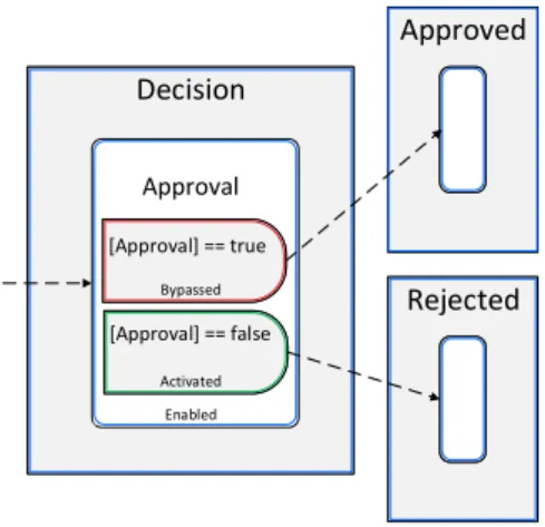
For decision step γApprovalI , two predicate steps ρItrue and ρIf alse exist. The predicate steps are equipped with expressions representing the actual predicate, λtrue : [Approval] ==true and λf alse : [Approval]==false, respectively (cf.
Figure 1). On provision of a value (w.l.o.g. it is assumed this value is false) forγIApproval, each predicate step is evaluated. ForρItrue, this evaluation returns false and accordingly markingµρ=Bypassed is set. MarkingBypassed indicates that this decision option is not valid and subsequent execution paths cannot be taken. For ρIf alse, the expression λf alse : [Approval] ==false evaluates to true andµρ =Activated is set. The markings of predicate steps ρItrue and ρIf alse are shown in Figure 3.
Rejected Rejected Approved Approved Decision
Decision
Approval
Enabled [Approval] == false
Activated [Approval] == true
Bypassed
Fig. 3.Decision step execution status Once each predicate step ρI has
been evaluated, the results affect the marking of the decision step γDecI it- self. In general, two cases need to be distinguished.
First, if all predicate steps possess markingµρ =Bypassed, the decision stepγDecI must be marked asBlocked.
This marking indicates that the pro- visioned value did not lead to a suc- cessful evaluation of the decision op- tions, and the execution of the lifecy- cle process can therefore not proceed.
To rectify the issue, a new value for γDecI needs to be provided. In turn, this triggers another evaluation of the predicate steps, ensuring that process
execution is not stuck when an invalid value has been provisioned.
In the second case, at least one of the predicate steps’ expressions evalu- ate to true and process execution may proceed. This is the case in Figure 3 with the predicate steps of γApprovalI . Decision step γDecI becomes marked as µγ =Activated. Subsequently, a series of marking changes occurs, leading to the decision step and its predicate steps with markingµρ=Activated to be marked as Unconfirmed. For decision steps, this raises several challenges that need to be solved in regard to its outgoing transitions becoming enabled. First, to allow modeling sophisticated decisions, it is permitted that predicates overlap, i.e., for a given data value, two or more predicates may evaluate to true. In turn, this might lead to the simultaneous enabling of outgoing transitions of the predicate steps. This is not permitted, as for example two states may be become active at the same time. For this reason, lifecycle processes perform apriority evaluation when multiple transitions are about to become enabled. Each transitionτI has an assigned priority τI.p (cf. Definition 2). Only the transition with the high- est priority becomes enabled, whereas all others are marked as Bypassed. The priorities are assigned by the process modeler at design time, allowing for full control over decision options with overlapping predicates.
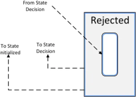
Handling Backwards Transitions and Invalidation Events Consider again the example from before, where at the moment the lifecycle process has termi- nated andσRejectedI is the active state. In this situation, a user decides he wants to revise his decision for approval and thus change the value of γApprovalI from false to true. After σIRejected had become active, two backwards transition in- stancesψIT oInit andψIT oDecbecame confirmable, i.e., their marking changed to µψ =Confirmable. In consequence, two “backwards transition confirm request”
events were created, one for each backwards transition, and then were stored in Eθ.
Rejected Rejected
To State Initialized
To State Decision From State
Decision
Fig. 4.Backwards transitions
This allows going back to state σInitializedI , by usingψT oInitI , or going back to σIDecision, by using ψT oDecI . However, only one state may be ac- tive at once. Therefore, only one backwards transition may be taken.
To revise the value of γApprovalI , ψT oDecI must be confirmed. Confirm- ing ψT oDecI causes its marking to change to µψ = Ready. Analogously to a step, a completion event is cre- ated, which removes the correspond- ing “backwards transition confirm re- quest” event from Eθ. Subsequently, σIRejectedis marked asµσ=W aitingandσIDecisionis marked asµσ=Activated, which allows altering the value ofγApprovalI totrue. AsσRejectedI is no longer ac- tive,ψIT oInitandψT oDecI become marked asµψ =Waiting. Resetting the mark-
ings of bothψIT oInit,ψT oDecI , andσRejectedI toWaiting enables their reuse, e.g., if the value ofγApprovalI remains unchanged and the same path is taken again.
With stateσIDecisionbecoming active again, it is possible to change the value ofσApprovalI . However, the “backwards transition confirm request” event belong- ing to ψT oInitI is still stored in Eθ, despite ψT oInitI having been marked with µψ=Waiting, i.e., confirmingψT oInitI is no longer possible. Obviously, this con- stitutes an inconsistency between the forms and the lifecycle process. The form displays a button with the option that ψT oInitI can be confirmed, but on press- ing the button the PHILharmonicFlows system produces an error and other, possibly worse, side effects. As a consequence, the operational semantics include invalidation events, with the purpose to remove invalid or obsolete execution events from event storage Eθ. An invalidation event occurs when entities with a request event, e.g., backwards transitions, are not successfully completed, but become changed due to other circumstances, e.g., the confirmation of another backwards transition.
Request events, completion events, and invalidation events are used in many more situations than discussed above. The basic principles, however, are always the same, and, embedded in the overall operational semantics, provide a robust and flexible way to acquire data values for lifecycle processes. The imperative-like modeling style of lifecycle processes, from which forms can be auto-generated di- rectly, significantly reduces modeling time and efforts. The operational semantics provide the necessary flexibility to users interacting with the forms. Furthermore, the use of forms and the emulation of standard form behavior simplifies the usage of the PHILharmonicFlows system for non-expert users.
Overall, this section described the functional aspects of the operational se- mantics of lifecycle processes. The technical implementation of these operational semantics with theProcess Rule Framework is presented in Section 4.
4 The Process Rule Framework
In the description of the operational semantics of lifecycle processes (cf. Section 3), at the lowest level, progress is driven by the change of markings. Marking changes elicit the creation of execution events, which, in turn, results in user actions, e.g., the provision of a data value for an attribute. This user interac- tion is reflected in the lifecycle process by setting new markings. This may be viewed as a chain of events, and, consequently, event-condition-action rules are used as the technical basis for the technical implementation of the operational semantics. In PHILharmonicFlows, a specialized variant of ECA rules, denoted as process rules, is employed for this purpose. Process rules and the means to specify them constitute one part of the process rule framework. To create an execution sequence, such as the one described in Section 3.2, process rules need to formprocess rule cascades, i.e., a rule triggers an event, which may trigger an- other rule, which again triggers an event. Furthermore, process rules are uniquely suited to deal with the different eventualities emerging during the execution of lifecycle processes. For example, a state σI may become active in context of
normal process execution progress or due to the use of a backwards transition ψI. Subsequently, different follow-up measures may be required, e.g., the reset- ting of markings for stepsγI ∈σI.ΓI in case the backwards transition became activated.
The basic definition of a process rule is given in Definition 3. In order to distinguish these symbols from symbols used in the definition of object instances, superscriptR is used.
Definition 3. A process rule pRhas the form (, eT, CR, AR) where – is an event triggering the evaluation of the rule.
– eT is an entity type, e.g., a step type γT. – CR is a set of preconditions in regard to eT. – AR is a set of effects.
Process rulespR may be evaluated, i.e., their preconditions CR are checked and, if all are fulfilled, the effectsARare applied. An evaluation is triggered when the eventoccurs. Eventsare always raised by a particular entity instanceeI, e.g., a stepγI or a transitionτI.eT is an entity type that provides the context for defining conditions and effects. Furthermore, it provides an implicit precondition, meaning a rule is not evaluated if the entity instanceeI raisingwas not created from eT. PreconditionsCR check different properties of an entity, e.g., whether the entity has a specific marking. EffectsARapply different effects to an entity, e.g., setting the marking of an entity. Note that preconditions and effects are not limited to properties belonging to instances ofeT. They may also access or set properties of neighbor entities. For example, a rule defined for a stepγT may have effects that set markings for the outgoing transitions τoutI ∈γI.ToutI of the corresponding step instance.
Fig. 5.Fluent interface definition of a marking rule in code
In the PHILharmonicFlows implementation, process rules are created using a domain-specific language. Figure 5 shows an example of how a process rule is
represented. Process rules are often subject to change, as new features for PHIL- harmonicFlows are added or errors in lifecycle process execution are resolved.
In order to be able to quickly adapt a process rule, the process rule framework uses afluent interfacefor process rule specification, i.e., the domain-specific lan- guage is structured to resemble natural prose text. This allows for both a high readability and maintainability.
The operational semantics introduced in Section 3 allow identifying different use cases for process rules. For example, one type of process rule raises execution events based on specific markings, while another type reacts to user input and sets appropriate markings. Accordingsly, process rules are subdivided based on their purpose. The type determines the general type of preconditions and effects, e.g., preconditions ofmarking rules check predominantly for specific markings.
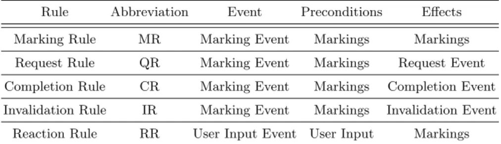
The different types of process rules are summarized in Table 1. Request rule, completion rule, and invalidation rule are subsumed under the term execution rule (ER).
Table 1.Overview over the types of process rules
Rule Abbreviation Event Preconditions Effects
Marking Rule MR Marking Event Markings Markings
Request Rule QR Marking Event Markings Request Event Completion Rule CR Marking Event Markings Completion Event Invalidation Rule IR Marking Event Markings Invalidation Event
Reaction Rule RR User Input Event User Input Markings
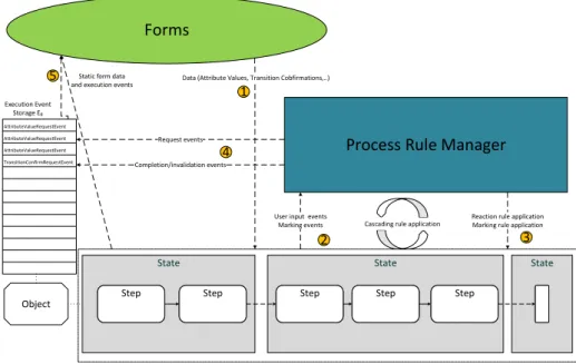
The most common event that is raised during the execution of a lifecycle process instance is amarking event.An entity instanceeI raises a marking event whenever its markingeI.µis changed. In order to determine which process rule needs to be applied, the event is gathered by the process rule manager (PRM) of the lifecycle process. The process rule manager is a small and lightweight execution engine for process rules and constitutes the other part of the process rule framework. Figure 6 shows a schematic view of the process rule manager and its interactions with the lifecycle process and the (auto-generated) forms.
Starting at 1in Figure 6, data has been entered into a form field. The data is then passed on to the lifecycle processθI and the corresponding stepγI. As γI has received a value, the step raises a user input event 2. The event is passed on to the process rule manager, which receives all events from its corresponding lifecycle process θI and evaluates appropriate rules, i.e., process rules pR with pR.eT =σT are not evaluated if the entity creating the event has typeγT. Note that this implicit precondition significantly reduces the search space for process
State State State Step
Step StepStep StepStep StepStep StepStep
AttributeValueRequestEvent AttributeValueRequestEvent AttributeValueRequestEvent TransitionConfirmRequestEvent
Object
Execution Event Storage Eθ
Process Rule Manager Forms
Static form data and execution events
User input events Marking events
Reaction rule application Marking rule application Cascading rule application
Request events
Completion/invalidation events
Data (Attribute Values, Transition Cobfirmations,..)
1
2 3
4 5
Fig. 6.Process rule manager and schematic process rule application
rule application. Once the PRM has identified all currently applicable rules, the effects of each rule are applied. In the example, the PRM identifies a reaction rule and applies its effects to the appropriate entities in the lifecycle process 3. Applying the effects from the reaction rule application raises marking events, which trigger a completion rule and a marking rule in the PRM. The completion rule raises a completion event 4, removing the request event for the mandatory form field from event storageEθofθI. In parallel, the marking rule sets markings for the outgoing transitions TI of stepγI. This again creates marking events, resulting in a cascade of marking rules, i.e., the PRM alternates between 2 and 3in Figure 6. The process rule cascade stops when the next step becomes marked with µγ =Enabled. This raises a request event, which is deposited in event storageEθ . When a user views a form, the updated event storage4 Eθ and the static form data are combined into a new form 5. When the user enters data for the next form field, the cycle starts again at 1.
When a user fills out a form, the form is expected to tell the user immediately which form field is required next after providing data for a form field. Long processing times are prohibitive for the usability of the PHILharmonicFlows process management system. In order to have full control over processing times and the tight connection of process rules with lifecycle process entities, it was decided to implement the PRM as a custom, lightweight rule engine. A custom PRM implementation offers a fine-grained control over process rule application.
By default, the PRM handles events in the order in which they arrive (FIFO principle). However, in several cases, the handling of specific events needed to be
delayed or accelerated in order to ensure a form processing in compliance with the operational semantics. For example, an eventeτtriggering the transitionτI from a source state σIsource to a target stateσItarget is, under certain circumstances, raised before all stepsγI ∈σIsource.ΓI have been processed. This results in errors in the application of the process rules, as the target stateσItargetalready received µσ=Activated when events fromγI ∈σsourceI .ΓIarrive at the PRM. To prevent such errors, the handling of the state transition eventeτ must be delayed until all stepsγI in the source stateσsourceI have finished processing. In consequence, the PRM was extended with a priority queue that retains the FIFO principle, but allows assigning different priorities to events, accelerating or delaying them as needed.
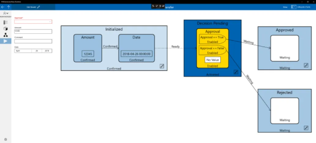
Fig. 7.Run-time environment of PHILharmonicFlows, executing a Transfer lifecycle process
Figure 7 shows the run-time environment of the PHILharmonicFlows proto- type, which is currently executing aTransfer object. Besides the advantages for the application of process rules, the lightweight nature of the PRM also proves beneficial for the transition of PHILharmonicFlows to a microservice-based ar- chitecture. The PRM was initially conceived as a monolithic rule engine, i.e., all lifecycle processes use the same instance of the PRM. Currently, PHILhar- monicFlows is moving towards a hyperscale architecture [2], based on a mi- croservice framework. A microservice is a lightweight and independent service that performs single functions and interacts with other microservices in order to realize a software application. In this new hyperscale architecture, an object and its lifecycle process are implemented as a single microservice. A continued use of a single PRM instance generates a significant performance overhead due to the necessary message exchanges between the PRM and the microservices.
The single PRM instance is a bottleneck and puts a limit on the scalability of the microservice-based architecture, i.e., it would no longer be warranted to
designate the PHILharmonicFlows system as hyperscale. Furthermore, the com- munication overhead and the delays of process rule application in the PRM, due to the high number of events simultaneously created by the object instance microservices, would negatively affect the performance of the auto-generated forms.
Fortunately, the lightweight nature of the PRM offers a satisfactory solution.
By integrating an instance of the PRM into the microservice of each object in- stance, no message exchanges between PRM and lifecycle process are required.
Furthermore, a PRM instance is only responsible for exactly one lifecycle process instance. This eliminates the delays in rule application due to the processing of other lifecycle processes. This solution offers sufficient performance for dis- playing dynamic forms while retaining the hyperscale property of the PHILhar- monicFlows microservice-based architecture. The approach to integrate a PRM instance into a microservice will also be used with the implementation of coor- dination processes, where it will provide the same benefits.
Performance measurements of the whole PHILharmonicFlows prototype are a delicate endeavor and are therefore subject to a separate publication, where the performance measurements can receive the necessary context and diligence. As a fully integrated system supporting high scalability and parallelism through mi- croservices, where also multiple concepts work together (objects, their relations, lifecycles and coordination processes to govern object interactions) to achieve a meaningful business process, a performance evaluation of executing one single lifecycle process is not particularly enlightening. A publication on performance aspects of the PHILharmonicFlows systems is therefore subject to future publi- cations.
5 Related Work
Opus [8, 10] is a data-centric process management system that bases its pro- cesses on Petri nets. Petri nets are a popular and well-established formalism for modeling business processes. Additionally, Petri nets provide several verification techniques, e.g., soundness checks or deadlock detection, which may also be ap- plied to verify process model correctness. In Opus, the Petri net formalism is extended with structured data tuples, which substitute the places of a standard Petri net. The transitions of this extended Petri net provide operations on the data, e.g., operations derived from operations of relational algebra. The Opus approach does not support automatically generating forms from process models.
Furthermore, Petri nets are inherently more rigid in their execution and do not provide the same built-in flexibility as PHILharmonicFlows and the operational semantics of lifecycle processes. However, Opus is capable to explicitly model the different execution paths to provide flexible process execution. Opus provides an implemented prototype of the approach [9].
Case Handling [7, 21, 24] defines a case in terms of activities and data objects.
Activities are ordered in an acyclic graph in which edges represent precedence relations. To execute an activity, all precedence relations before the activity must
be fulfilled. Furthermore, the execution of an activity is restricted by data bind- ings. A data binding represents a condition so that a data object must have a specific value at run-time. The values of the data objects are acquired by forms, which are associated with activities. While case handling possesses forms, it is unclear whether these can be auto-generated from the activities or must be cre- ated manually. While both case handling and PHILharmonicFlows use an acyclic graph to represent processes, the operational semantics for lifecycle processes in PHILharmonicFlows allows for data to be acquired at any point in time. A case acquires data by activities and that activities have a precedence relation, the same flexibility in regard to data acquisition is not possible. A detailed compari- son between case handling and object-aware process management was performed in [4].
The Guard-Stage-Milestone (GSM) meta-model [14] is a declarative notation for specifying artifact-centric processes [5, 13, 17]. An artifact consists of an infor- mation model, i.e., attributes and a lifecycle model. The lifecycle model is spec- ified using GSM. Its operational semantics are based on Precedent-Antecedent- Consequent rules and possess different, but semantically equivalent formulations [6]. In GSM, tasks provide the means to write attributes and acquire data. Be- cause of being declarative, guards, stages and milestones may be used in such a way that flexible data acquisition, within certain constraints, becomes possible.
Tasks may be defined so that attributes may be written at any point in time and may be restricted, if necessary. Lifecycle processes defined in GSM are able to react to the newly acquired data and might be more flexible than lifecycle processes in PHILharmonicFlows. However, as a severe drawback, much of this flexibility in data acquisition must be implemented by the process modeler. Fur- thermore, the is no auto-generation of forms from GSM-specified lifecycle models within the artifact-centric approach.
CMMN [18] is a standard notation for case management as proposed by OMG. The notation is closely inspired by GSM and its execution semantics and therefore inherits many of the same advantages and disadvantages. As such, flexibility in practice has to be provided by the model and is not simply provided by the operational semantics. Also, automatic generation of dynamic forms it not supported.
Fragment-based case management [3, 12] is a promising approach that defines business processes in form of pre-specified process fragments. Fragments are specified using activities and control flow. The execution order of fragments is, in principle, completely free, i.e., any process process fragment may be executed at any point in time. This freedom is only limited by data conditions that govern the activation of a process fragment, i.e., a process fragment may only be executed if the data conditions are met. In turn, process fragments may generate new data to fulfill other data conditions and subsequently enable more process fragments.
As data is mostly required to enable process fragments and their activities, it is unclear whether automatic form generation with dynamic control by the process is achievable. Through breaking rigid control flow ordering of activities with the use of process fragments, their flexible execution may only be achieved by
modeling appropriate data conditions and is not automatically provided by the operational semantics, as accomplished in PHILharmonicFlows.
6 Summary and Outlook
The PHILharmonicFlows project is a full, though prototypical, data-centric pro- cess management system incorporating modeling and execution environments.
One aspect of this system is to have highly flexible executions of object lifecycle processes that require minimal effort on part of the process modeler. The sci- entific contribution of this paper is to showthat the intended level of flexibility has been achieved. As proof, it is shown exactly how the flexibility is achieved by describing its implementation and inner workings in full detail.
The technical implementation of the operational semantics of lifecycle pro- cesses in object-aware process management is achieved by process rules, which govern the changing of markings and the creation of execution events. This paper presented the process rule framework, for which two aspects need to be empha- sized. First, the process rule framework ensures that lifecycle processes execute correctly and also provides the technical basis for the operational semantics of coordination processes in PHILharmonicFlows. Coordination processes, as the name suggests, coordinate lifecycle processes of multiple objects, so that com- plex business processes can be realized. Its operational semantics will be based on the process rule framework as well. Second, a performant, efficient and light- weight technical basis for enacting lifecycle processes and coordination processes is crucial for the transition of PHILharmonicFlows to a hyperscale architecture.
The operational semantics of lifecycle processes provide a flexible acquisition of data, while modeling efforts are minimal due to an modeling style that is akin to an imperative style. The flexibility is not provided by the lifecycle process model, but by the operational semantics. The model of the lifecycle process and the operational semantics together provide the means to auto-generate dynamic forms.
Acknowledgments. This work is part of the ZAFH Intralogistik, funded by the European Regional Development Fund and the Ministry of Science, Research and the Arts of Baden-W¨urttemberg, Germany (F.No. 32-7545.24-17/3/1)
References
1. Andrews, K., Steinau, S., Reichert, M.: Enabling Fine-grained Access Control in Flexible Distributed Object-aware Process Management Systems. In: 21st IEEE Int’l Conf. on Enterprise Distributed Object Computing (EDOC) (2017)
2. Andrews, K., Steinau, S., Reichert, M.: Towards Hyperscale Process Management.
In: 8th Int’l Workshop on Enterprise Modeling and Information Systems Architec- tures (EMISA). pp. 148–152. CEUR Workshop Proceedings, CEUR-WS.org (2017) 3. Beck, H., Hewelt, M., Pufahl, L.: Extending Fragment-Based Case Management with State Variables. In: Business Process Management Workshops. pp. 227–238.
Springer, Cham (2017)
4. Chiao, C.M., K¨unzle, V., Reichert, M.: Enhancing the Case Handling Paradigm to Support Object-aware Processes. In: 3rd Int’l Symposium on Data-Driven Process Discovery and Analysis (SIMPDA). pp. 89–103. CEUR Workshop Proceedings, CEUR-WS.org (2013)
5. Cohn, D., Hull, R.: Business Artifacts: A Data-centric Approach to Modeling Busi- ness Operations and Processes. Bulletin of the IEEE Computer Society Technical Committee on Data Engineering 32(3), 3–9 (2009)
6. Damaggio, E., Hull, R., Vacul´ın, R.: On the Equivalence of Incremental and Fix- point Semantics for Business Artifacts with Guard–Stage–Milestone Lifecycles. In- formation Systems 38(4), 561–584 (2013)
7. Guenther, C.W., Reichert, M., van der Aalst, W.M.P.: Supporting Flexible Pro- cesses with Adaptive Workflow and Case Handling. In: IEEE 17th Workshop on Enabling Technologies: Infrastructure for Collaborative Enterprises. pp. 229–234 (2008)
8. Haddar, N., Tmar, M., Gargouri, F.: A Framework for Data-Driven Workflow Man- agement: Modeling, Verification and Execution. In: 24th Int’l Conf. on Database and Expert Systems Applications (DEXA). vol. 8055, pp. 239–253. Springer (2013) 9. Haddar, N., Tmar, M., Gargouri, F.: Opus framework: A Proof-of-Concept Imple- mentation. In: IEEE/ACIS 14th Int’l Conf. on Computer and Information Science (ICIS). pp. 639–641 (2015)
10. Haddar, N., Tmar, M., Gargouri, F.: A Data-centric Approach to Manage Business Processes. Computing 98(4), 375–406 (2016)
11. Haisjackl, C., Barba, I., Zugal, S., Soffer, P., Hadar, I., Reichert, M., Pinggera, J., Weber, B.: Understanding Declare Models: Strategies, Pitfalls, Empirical Results.
Software & Systems Modeling 15(2), 325–352 (2016)
12. Hewelt, M., Weske, M.: A Hybrid Approach for Flexible Case Modeling and Execu- tion. In: Business Process Management Forum. pp. 38–54. Springer, Cham (2016) 13. Hull, R., Damaggio, E., de Masellis, R., Fournier, F., Gupta, M., Heath,III, Fenno Terry, Hobson, S., Linehan, M., Maradugu, S., Nigam, A., Sukaviriya, P.N., Vacul´ın, R.: Business Artifacts with Guard-Stage-Milestone Lifecycles: Managing Artifact Interactions with Conditions and Events. In: 5th ACM Int’l Conf. on Distributed Event-based System (DEBS), 2011. pp. 51–62. ACM (2011)
14. Hull, R., Damaggio, E., Fournier, F., Gupta, M., Heath,III, Fenno Terry, Hobson, S., Linehan, M., Maradugu, S., Nigam, A., Sukaviriya, P.N., Vacul´ın, R.: Introduc- ing the Guard-Stage-Milestone Approach for Specifying Business Entity Lifecycles.
In: 7th Int’l Workshop on Web Services and Formal Methods (WS-FM) 2010. Lec- ture Notes in Computer Science, vol. 6551, pp. 1–24. Springer (2011)
15. K¨unzle, V., Reichert, M.: A Modeling Paradigm for Integrating Processes and Data at the Micro Level. In: 12th Int’l Working Conf. on Business Process Modeling, Development and Support (BPMDS). pp. 201–215. Lecture Notes in Business In- formation Processing, Springer (2011)
16. K¨unzle, V., Reichert, M.: PHILharmonicFlows: Towards a Framework for Object- aware Process Management. Journal of Software Maintenance and Evolution: Re- search and Practice 23(4), 205–244 (2011)
17. Nigam, A., Caswell, N.S.: Business Artifacts: An Approach to Operational Speci- fication. IBM Systems Journal 42(3), 428–445 (2003)
18. Object Management Group: Case Management Model and Notation (CMMN), Version 1.1 (2016)
19. Pesic, M., Schonenberg, H., van der Aalst, W.M.P.: DECLARE: Full Support for Loosely-Structured Processes. In: 11th IEEE Int’l Conf. on Enterprise Distributed Object Computing (EDOC). p. 287 (2007)
20. Pichler, P., Weber, B., Zugal, S., Pinggera, J., Mendling, J., Reijers, H.A.: Imper- ative versus Declarative Process Modeling Languages: An Empirical Investigation.
In: Business Process Management Workshops: BPM 2011 Int’l Workshops, Revised Selected Papers, Part I. pp. 383–394. Springer (2012)
21. Reijers, H.A., Rigter, J.H.M., van der Aalst, W.M.P.: The Case Handling Case.
International Journal of Cooperative Information Systems 12(03), 365–391 (2003) 22. Steinau, S., Andrews, K., Reichert, M.: The Relational Process Structure. In: 30th Int’l Conf. on Advanced Information Systems Engineering (CAiSE). pp. 53–67.
Springer (2018)
23. Steinau, S., K¨unzle, V., Andrews, K., Reichert, M.: Coordinating Business Pro- cesses Using Semantic Relationships. In: 19th IEEE Conf. on Business Informatics (CBI). pp. 33–43. IEEE Computer Society Press (2017)
24. van der Aalst, W.M.P., Weske, M., Gr¨unbauer, D.: Case Handling: A New Paradigm for Business Process Support. Data & Knowledge Engineering 53(2), 129–162 (2005)
25. Weber, B., Mutschler, B., Reichert, M.: Investigating the Effort of Using Business Process Management Technology: Results from a Controlled Experiment. Science of Computer Programming 75(5), 292–310 (2010)