Ulm University| 89069 Ulm | Germany Faculty of Engineering, Computer Science and Psychology
Institute of Databases and Information Systems
Workflows on Android:
A Framework Supporting Business Process Execution and Rule-Based Analysis
Master Thesis at Ulm University
Submitter:
Wolfgang Wipp
wolfgang.wipp@uni-ulm.de
Reviewer:
Prof. Dr. Manfred Reichert Dr. Rüdiger Pryss
Supervisor:
Johannes Schobel 2016
Version March 2, 2016
c
2016 Wolfgang Wipp
This work is licensed under the Creative Commons. Attribution-NonCommercial-ShareAlike 3.0 License. To view a copy of this license, visit http://creativecommons.org/licenses/by-nc-sa/3.0/de/
or send a letter to Creative Commons, 543 Howard Street, 5th Floor, San Francisco, California, 94105, USA.
Satz: PDF-LATEX 2ε
Abstract
In companies, Business Process Management is often supported by Process-aware information systems(PAIS). However, such systems are mostly restricted to stationary desktop computers. To overcome this restriction, smart mobile devices may be used for mobile business process execution. However, with traditional PAIS having a client-server architecture, the computation is done on server side, whereas the client only visualizes business process tasks and interacts with the user. Therefore, smart mobile devices must rely on their mobile connection to provide PAIS features to its users.
A possible solution is the transfer of server side features to the smart mobile device itself, enabling the latter to instantiate business process models and analyze business process instances by itself, without the need of a direct connection to a workflow-server.
This thesis presentsWorkflows on Android (WOtAN), a modular and flexible framework for business process management running on Android smart mobile devices. However, the thesis focuses on flexible and robust business process execution as well as the analysis of business process instances. For this, predefined evaluation rules are applied on data that was collected during business process instance execution.
Different concepts and interesting implementation aspects are presented in this thesis.
Further, an application scenario is shown, where WOtAN is used to properly support a mobile data collection application.
Acknowledgement
First of all, I thankJohannes Schobel for his important mentoring through all this thesis.
Further, I’d like to thank my fellow students, especially Michael, Bernd, Steini, and Markusfor their support. Furthermore, I thankKenny Loggins, who’s songDanger Zone escorted me through the long nights of implementation and writing.
A special thanks goes toAndreaandFlorian, who saved me a huge amount of time by styling the graphical user interface for the use case project.
Finally, I thank my family for motivating me during the whole thesis, again ,and again, and again...
Contents
1 Introduction 1
1.1 Purpose of this Thesis . . . 2
1.2 Structure of this Thesis . . . 3
2 Fundamentals 5 2.1 Object-Relational Mapper . . . 5
2.1.1 General Overview . . . 5
2.1.2 Model Generation Approaches . . . 6
2.2 Android . . . 8
2.2.1 Application Structure . . . 9
2.2.2 Application Communication . . . 9
2.3 ADEPT2 . . . 10
2.3.1 Process Model . . . 10
2.3.2 Process Execution Logic . . . 12
3 Related Work 15 3.1 jBPM . . . 15
3.2 MARPLE . . . 16
3.3 Questionnaire Process Execution Engine . . . 17
3.4 Discussion . . . 17
4 Requirements 19 4.1 Functional Requirements . . . 19
4.2 Non-Functional Requirements . . . 20
4.3 Discussion . . . 21
5 Concepts and Architecture 23 5.1 General Overview . . . 23
5.2 WOtANExecution . . . 25
5.2.1 Concepts . . . 26
Contents
5.2.2 Architecture . . . 29
5.3 WOtANAnalysis . . . 32
5.3.1 Concepts . . . 32
5.3.2 Architecture . . . 33
6 Implementation Aspects 35 6.1 Interface Design . . . 35
6.2 Executable Business Process Management . . . 36
6.2.1 Structure . . . 36
6.2.2 Loading at Runtime . . . 37
6.2.3 Development Challenges . . . 38
6.3 Object-Relational Mapping . . . 39
6.3.1 Schema Generation . . . 40
6.3.2 Database Communication . . . 40
6.4 Rule Evaluation Process . . . 42
6.4.1 General Usage . . . 42
6.4.2 Rule Evaluation . . . 43
7 Application Scenario: Mobile Data Collection Application 47 7.1 Introduction . . . 47
7.2 System Architecture . . . 48
7.2.1 Questioneer . . . 49
7.2.2 QuestionRule . . . 49
7.2.3 Questionizer . . . 49
7.2.4 Questionnaire . . . 49
7.3 Using WOtAN in the Context of Mobile Data Collection Applications . . . 50
7.3.1 Overall Architecture . . . 50
7.3.2 Executing Questionnaires using WOtANExecution . . . 50
7.3.3 Evaluating Questionnaires using WOtANAnalysis . . . 52
7.3.4 Page Executable Business Process . . . 52
viii
Contents
8 Conclusion 55
8.1 Vision . . . 56
A Sources 65 A.1 Dynamic EBP Loading . . . 65
A.2 Example Layout Inflater Factory . . . 66
A.3 greenDAO Schema Generation Code . . . 66
A.4 Database Access with GreenDAO . . . 67
1
Introduction
To sustain on global market, companies must act in a flexible and agile way. For example, they must react on market changes rapidly and continuously improve their products and services. Currently, business process management offers promising perspectives to achieve these goals. As a result, optimized business processes improve companies in terms of costs, time to market, and product quality [1]. Despite the fact that BPM does not require an IT system support, most companies useProcess-aware information systems(PAISs) [2] to support process management.
During the last years, PAISs have become very powerful systems, providing flexibility by separating application code from the business process logic [3]. As a result, dynamic changes of business processes became possible, without updating PAIS applications.
PAISs are most likely designed in a Rich-Client/Thin-Server architecture, where the server provides all process management features, whereas the client is only responsible for visualization and interaction [4]. Unfortunately, as for all IT systems, PAISs are locally restricted to given IT-endpoints (desktop computer, laptops). Therefore, some domains may have processes, that cannot be executed in a PAIS’s reach [5]. In clinical ward rounds, for example, the doctor may first perform thereal-world business process task, then go back to an computer and perform the IT supported business process task executed on a PAIS. This workaround is error-prone, as collected data may be transcribed manually. Further, the duplicate enactment of business process tasks, as well as media breaks, are inefficient. Within larger processes there may exist only few business process tasks, that are not in reach of the supporting PAIS.
Since a business process’ state of execution is stored in the PAIS, the duplicate en-
1 Introduction
supported execution. The system does not know, that the real world task is already been performed and what outcome it has. This delay of execution may become a severe prob- lem in time critical processes [6]. As a result,mobile IT support for business processes (i.e., enable workers to perform IT supported business process tasks at any location and at any time), is a highly desired feature [7, 8, 9].
With the fast dissemination ofsmart mobile devices (smart phones, tablet computers) as well as their technological development over the last years, the power of common office computers shrunk to the size of a pocket device. Therefore, smart mobile devices may serve as possible hardware for mobile IT support for business processes. They are handy enough to be carried anywhere, at any time, providing enough computation power to work on sophisticated process tasks.
1.1 Purpose of this Thesis
Client and server of a PAIS must be connected all the time to function properly. This is no problem with locally set up workstations but can become a problem with smart mobile devices and their respective mobile connection. For example, a sales representative may need to start the companiescontract processat a customer’s location, with no available mobile connection. However, if no connection to the PAIS’s server is available, the smart mobile device may not be able to perform process control features. A missing mobile connection may occur because of several reason, like standing in a dead spot, network service provider issues, or PAIS server issues.
To overcome such difficulties, this thesis introducesWorkflows on Android (WOtAN for short), focusing on process execution (WOtANExecution) and process analysis using rules (WOtANAnalysis). WOtAN thereby is a framework for dedicated business process management on Android smart mobile devices, using current state-of-the-art PAIS technology. Furthermore, WOtAN enables smart mobile devices to manage and execute business processes without any external communication, hence eliminating the issue of a lost mobile connection.
2
1.2 Structure of this Thesis
1.2 Structure of this Thesis
The structure of this thesis is as follows: Chapter 2 describes relevant fundamentals in the context of this thesis. Subsequently, Chapter 3 introduces related work and elaborates common features as well as differences in state-of-the-art products. Next, Chapter 4 lists and discusses both functional and non-functional requirements for WOtANExecution and WOtANAnalysis. Chapter 5 introduces the overall concepts and presents the architecture of the developed lightweight mobile process engine. Afterwards, Chapter 6 provides deeper insight into the implementation, specifically focusing on theExecutable Business Process, a software template for Android executed in business process tasks during runtime. Following, Chapter 7 illustrates the use of WOtAN within a mobile data collection application scenario. Finally, Chapter 8 summarizes the thesis and proposes future work.
2
Fundamentals
This chapter introduces the fundamentals of this thesis. First, Section 2.1 describes object-relational mapping. Subsequently, Section 2.2 shows Android basics needed in this thesis. At last, Section 2.3 illustrates the, for the thesis relevant, concepts of ADEPT2.
2.1 Object-Relational Mapper
Object-oriented programming languages(OOP-Languages) andrelational databasesare based on different paradigms. Therefore, the communication between OOP-Languages and relational databases is difficult [10]. As a result,object-relational mapper (ORM) are developed to close the gap between object paradigm and relational paradigm.
This section introduces object relational mapping. Section 2.1.1 provides a general overview regarding object-relational mapping, whereas Section 2.1.2 presents different approaches for model generation.
2.1.1 General Overview
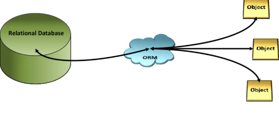
ORM simplifies and abstracts the communication between application and database.
Instead of manually creating objects and propagating them with database values, ORMs automatically map application classes to database tables, encapsulating the value to object mapping process, as illustrated in Figure 2.1. Hence, an application pro- grammer does not need database language experience, but can rely on application
2 Fundamentals
language based database access i.e., using automatically generated functions to query the database, insert or remove entries.
Relational Database
Figure 2.1: ORM Overview
Additionally, ORM reduces duplicate work by either generating the database schema or the application data classes. As a result, the application programmer needs to develop only one data model instead of two separate ones for database and application.
Accordingly, maintainability of such produced data models are drastically improved, as changes affect both database and application.
However, despite the lose decoupling from the database, a programmer should have basic knowledge of databases in general and good knowledge of specific database system used.
2.1.2 Model Generation Approaches
This section describes the automatic generation of a data model and the respective counterpart on either application or database side. There are several approaches for data model generation:
1. Model First: Create application side classes first and generate database tables based on them.
2. Database First: Create database tables first and generate application side classes based on them.
6
2.1 Object-Relational Mapper
3. Hybrid Generator: Both database tables and application classes are generated based on a meta model.
The following sections describe each approach and gives deeper insight.
1. Model First Approach
This approach generates database tables from previously written model classes. Map- ping respective classes to database tables can be achieved with different techniques.
First, annotations can be used to set database attributes i.e., table name for a class, primary key, include member as field. Listing 2.1 shows an example using ORMLite [11].
1 @DatabaseTable ( tableName = " accounts " ) 2 p ub li c class Account {
3
4 @DatabaseField ( i d = t r u e) 5 p r i v a t e S t r i n g name ;
6 @DatabaseField
7 p r i v a t e S t r i n g password ; 8
9 p ub li c Account ( ) {
10 / / ORMLite needs a no−arg c o n s t r u c t o r
11 }
12 p ub li c Account ( S t r i n g name , S t r i n g password ) {
13 t h i s. name = name ;
14 t h i s. password = password ;
15 }
16 / / G e t t e r and S e t t e r f o r a l l F i e l d s o f t h i s c l a s s
17 . . .
18 }
Listing 2.1: ORMLite Class Example
The@DataBaseTableannotation declares this class to be mapped to a database table with the nameaccounts, with the member variablenameas its primary key.
Using another technique, classes can be directly mapped to database tables by extending ORM specific abstract classes, as shown in Listing 2.2, using Sugar ORM [12].
1 p ub li c class Book extends SugarRecord { 2 S t r i n g name ;
3 S t r i n g ISBN ; 4 S t r i n g t i t l e ; 5 S t r i n g shortSummary ;
6 }
Listing 2.2: Sugar ORM Class Example
2 Fundamentals
The example shows aBookclass that has aname,ISBN,title, andshortSummary attribute. The super classSugarRecordtakes care of database mapping, including all member variables as respective columns within a table named as the class.
This approach is handy when an application data model already exists. Further, an application developer does not need database language experience to create a database schema.
2. Database First Approach
This approach takes a given database table schema and generates corresponding application classes. As mentioned in [13],doctrine, an ORM system for PHP, provides this feature. For this, doctrine generates an XML mapping file from which it generates the respective PHP class sources, as described in [14].
3. Hybrid Generator Approach
The hybrid generator approach neither take a data model nor a database schema to generate the other part, but uses a meta model to generate both. This meta model describes database and table features ,like primary keys, relations between them, and indexes. Furthermore, application features, like class hierarchies, or interface implementations may be defined. GreenDAO [15], which will be explained in more detail in Section 6.3, follows this approach.
2.2 Android
This section describes basic knowledge about the Android operating system, called Androidfor short. Therefore, the Android application structure, as well as inter-application communication is explained in more detail.
8
2.2 Android
2.2.1 Application Structure
Any Android application consists of the following parts:
• Sources: Java class files, later translated into DalvikVM byte code format.
• Resources: Resource files, like XML layout files, String values, or images.
• Assets: Files, that are not part of resources.
• Manifest: Contract file between the application and the operating system.
According to [16], resource files are stored in a predefined folder structure that allow multiple values, dependent on device screen size and location. TheManifestis an XML file responsible for presenting application information to Android. Such information is e.g., the package name of the application, which serves as global identifier, and implementedactivitieswith their processableintents. Additionally, permissions for device resources like the camera, storage and network service, are stored within theManifest [17].
After compiling, all parts are stored in anAndroid application package(apk). This is the only usable format to install applications on Android smart mobile devices.
2.2.2 Application Communication
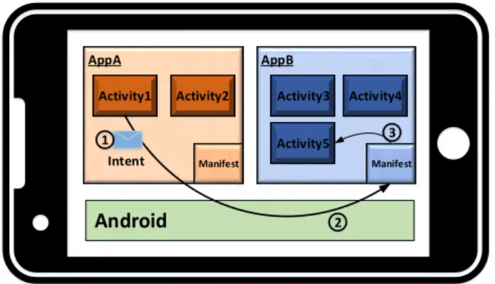
Communication betweenactivities[18] andfragments[19] are performed usingintents [20]. Thereby, an intent is a messaging object used to request an action from another application component [20], regardless of this component being part of the calling application or another one. As described in Section 2.2.1, theManifestact as the contract between respective application and Android. Therefore, every activity used inside an application must be registered in the applicationsManifestfile. Additionally, to be able to be called from an external application, anintent filter [20] must be added.
Using this contract, Android is able to search for applications installed on the device, that can serve a given intent. Figure 2.2 illustrates such an activity call. AppA’s activity
2 Fundamentals
AppA AppB
Android
Manifest Manifest
Activity1 Activity2 Activity3 Activity4
Activity5 Intent
1
2 3
Figure 2.2: Calling Another Activity Using Intents
sends its intent to Android, which searches for matching, registered activities. For2
this, it uses the applications’Manifestfile. If a matching activity is found (in this case Activity5), Android automatically starts AppB with its activity Activity5. Optionally,3
Activity5 may return a result to its caller (Activity1) after execution. For sending this result, or more general any data between activities, intents have a common key-value storage inside, calledbundle[21].
2.3 ADEPT2
TheApplication Development based on Encapsulated Pre-modeled Process Templates (ADEPT2) project [4] started in 1995 aiming at delivering a next generation business process management technology. This section introduces relevant topics for this master thesis. Therefore, Section 2.3.1 describes the process model of ADEPT2, whereas Section 2.3.2 illustrates ADEPT2’s concept of process execution.
2.3.1 Process Model
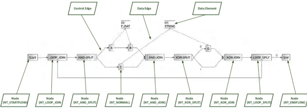
ADEPT2 process models are based on acyclic graphs [22, 23]. It consists of nodes, control edges,data elements, anddata edges[24]. One node is one step in the process
10
2.3 ADEPT2
model. Control edges are unidirectional edges connecting two nodes and thereby determining the order of execution. Hence, if a control edge connects nodeAwithB, it means thatAmust be executed beforeB.
Nodes may have differentnode types[23]. Node typeNT_STARTFLOWmarks the start of a process model, consequentlyNT_ENDFLOWmarks the end of a process model. Note that a process model can only have one start and one end node. Further,NT_NORMAL is the node type used for declaring a node with one incoming and one outgoing control edge, thus describing a sequence of execution. Furthermore, NT_AND_SPLITsplits the control flow into multiple parallel control flow branches. In contrast,NT_XOR_SPLIT also splits the control flow, but allows only one of these branches to be selected and executed. At last, NT_LOOP_SPLIT declares a reverse jump to an earlier point of execution, enabling parts of a process model to be performed multiple times. Additionally, eachSPLITtype has a correspondingJOINtype, spanning acontrol block. ADEPT2 only allows control blocks with one incoming and one outgoing control edge. Additionally, control blocks may not overlap, but can be nested [25].
Data elements areprocess variablesstoring data during execution [25]. Data elements’
values are written and read by nodes. The access type is modeled with unidirectional data edges. On one hand, a data edge from a node to a data element meanswrite access. On the other hand, a data edge from a data element to a node declaresread access. Figure 2.3 shows an example process with all elements.
Node (NT_NORMAL)
Node (NT_ENDFLOW) Node
(NT_STARTFLOW)
Node (NT_AND_SPLIT)
Node (NT_AND_JOIN)
Node (NT_XOR_SPLIT)
Node (NT_XOR_JOIN
Node (NT_LOOP_SPLIT) Node
(NT_LOOP_JOIN
Control Edge Data Edge Data Element
Figure 2.3: Example Process with Additional Annotations
2 Fundamentals
To ensure structural correctness, ADEPT2 uses a principle calledcorrectness by con- struction [26] i.e., offering the process modeler only modeling options that keep the process model syntactically correct.
2.3.2 Process Execution Logic
During the execution of the process model, nodes are transitioning through different node states, as Figure 2.4 illustrates.
Figure 2.4: Node States Chart [25]
Initially, a node is in node stateNOT_ACTIVATED. In this state, a node is not ready to be performed. If all preconditions are met, a node switches into node stateACTIVATED.
Now, the node can be triggered to be performed, sending it in node stateSTARTED.
While executing this node, it can beSUSPENDEDto interrupt its current execution. Af- ter completion, a node changes into node state COMPLETED or, if an error occurred, FAILED.
Additionally to nodes, control edges are also marked during process execution. Control edges have 3edge states[23]:NOT_SIGNALED,TRUE_SIGNALED,FALSE_SIGNALED.
A control edge is in edge stateNOT_SIGNALEDonly when their source node is not in node stateCOMPLETED,SKIPPED, orFAILED. Further, a source node with node state
12
2.3 ADEPT2
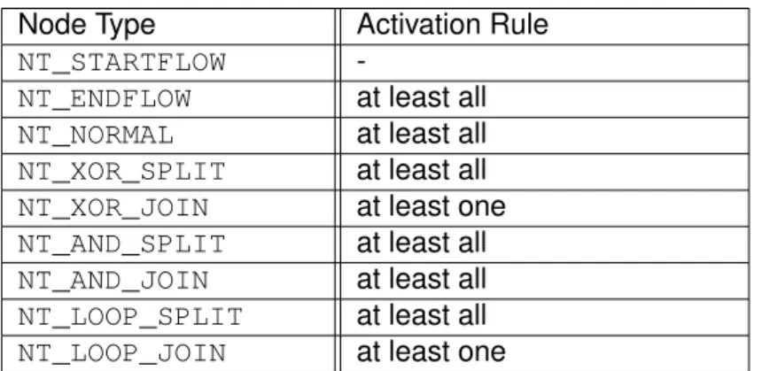
SKIPPEDorFAILEDgets the control edge intoFALSE_SIGNALED. For marking control edges with TRUE_SIGNALEDmarking rules dependent on the source node must be declared. Also, activation rules for nodes must be defined.
Both marking and activation rules are defined in [23]. Therefore, after completing a node of type NT_XOR_SPLIT, or NT_LOOP_SPLIT, only one of the outgoing control edges is markedTRUE_SIGNALED, all other are set toFALSE_SIGNALED. In contrast, completing nodes of any other type results in marking all outgoing control edges as TRUE_SIGNALED. For nodes, there are two rules for activation: either, all incoming control edges (at least all) or only one (at least one) must be markedTRUE_SIGNALED.
Table 2.1 shows the node types activation rule.
Node Type Activation Rule
NT_STARTFLOW -
NT_ENDFLOW at least all NT_NORMAL at least all NT_XOR_SPLIT at least all NT_XOR_JOIN at least one NT_AND_SPLIT at least all NT_AND_JOIN at least all NT_LOOP_SPLIT at least all NT_LOOP_JOIN at least one
Table 2.1: Activation Rules
Note that the start node does not have any incoming control edge and therefore must be activatedmanually at process execution start [23].
3
Related Work
Currently, several workflow engines are available that may be used on Android or are specifically designed for smart mobile device support. Sections 3.1 and 3.2 cover more general workflow engines, whereas Section 3.3 introduces the workflow engine previously used for the application scenario, described in Section 7. Finally, Section 3.4 discusses the provided features of each engine.
3.1 jBPM
jBPM [27] is a Business Process Management Suite, written entirely in Java. It offers a generic process execution infrastructure, allowing the integration of different process model notations (BPEL, EPC,..) but having a basic core engine, ready to execute BPMN 2.0 [28] process models. Further, jBPM offers features for modeling, monitoring, and managing process models and process instances. As this thesis deals with the issue of process execution and analysis, this section covers the execution concepts of jBPM.
Figure 3.1: jBPM Overview [29]
3 Related Work
As illustrated in Figure 3.1, a user interacting with the engine first must create astateful knowledge session for process execution. It is used for engine communication and needs a reference on aknowledge base. The latter holds all relevantprocess definitions (i.e., process models). Whenever a process is started, a newprocess instanceis created based on the respective process definition.
For domain specific tasks, jBPM uses so calledcustom work items [30]. A custom work item, however, is a BPMN<task>containing aWorkItemJava class to be used by aWorkItemHandler. A WorkItemHandler executes (or aborts) a given work item. TheWorkItemHandlergets registered at theWorkItemManagerof the stateful knowledge session used for process execution.
3.2 MARPLE
MAnaging Robust mobile Processes in a compLEx world(MARPLE) [31] is a light-weight process engine for smart mobile devices developed at Ulm University, enabling execution of central stored process models across different smart mobile devices by a client-server architecture. It consists of two main components [31], theMARPLE Mediation Center and theMARPLE Mobile Engine(of Figure 3.2).
Figure 3.2: General MAPRLE Architecture [31]
The MARPLE Mediation Center is responsible for the administration of process models and smart mobile devices. This includes, for example, deploying the MARPLE mobile
16
3.3 Questionnaire Process Execution Engine
engine on the smart mobile devices as well as modeling, transferring, and executing process models.
The MARPLE mobile engine takes care of process execution with pre-set Activity Templates, pre-manufactured application components, executed at runtime as process tasks [7]. Further, it tackles the issue of process derivation, as well as ad-hoc changes during the execution og a specific process instance. Therefore, it uses ADEPT 2.3 concepts. Finally, MARPLE Mobile Engine is responsible for communication to the MARPLE Mediation Center.
3.3 Questionnaire Process Execution Engine
In the context of a diploma thesis [32], a questionnaire process engine was implemented.
Used concepts are derived from ADEPT, resulting in a fully operational process execution engine. However, implementations for process tasks are stored inside the engine at build time, if a new process task implementation is needed or an already existing one needs to be modified, this results in updating the engine itself as well as the application using the engine. Further, communication between engine and application is based on XML documents. Hence, serialization of the latter results in high computation effort for communication.
3.4 Discussion
This chapter presented three different workflow engines for executing business processes.
First,jBPMis introduced. It is a very powerful light-weight engine which can be used on devices capable of running Java. However, jBPM is not specifically designed for smart mobile devices. In contrast,MARPLE, subsequently introduced, is specifically designed for the execution of business processes on smart mobile devices. This engine is also very powerful, but relies on a client-server architecture. Finally, the questionnaire process execution engine is presented. However, it lacks plug & play features for process task
3 Related Work
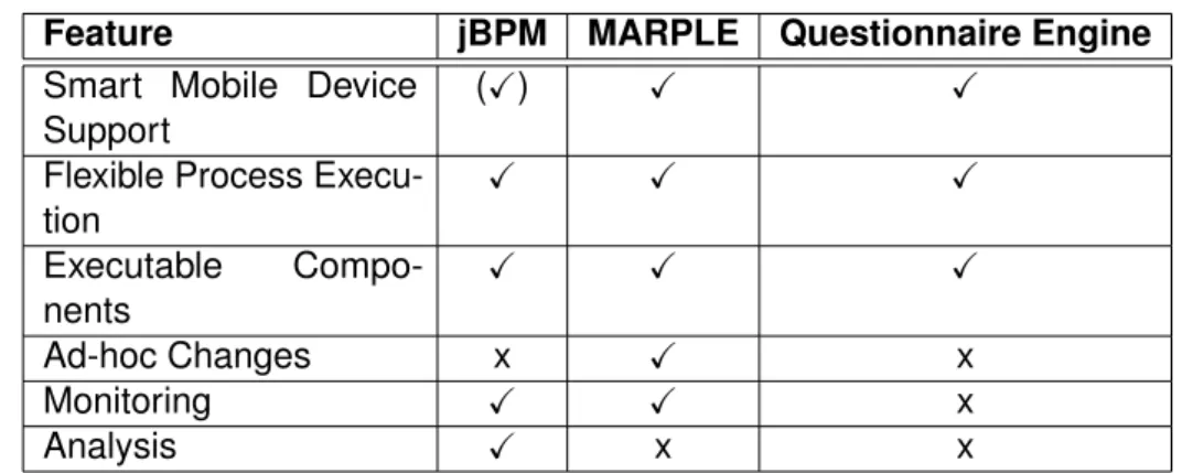
respective applications. Table 3.1 shows key-features for the discussed mobile process engines. The legend is as follow: ’(X)’ stands for partially available, ’X’ for fully available and ’x’ for not available
Feature jBPM MARPLE Questionnaire Engine Smart Mobile Device
Support
(X) X X
Flexible Process Execu- tion
X X X
Executable Compo- nents
X X X
Ad-hoc Changes x X x
Monitoring X X x
Analysis X x x
Table 3.1: Key-Features for Mobile Process Engines
18
4
Requirements
This chapter covers basic requirements for WOtAN, derived from the workflow engines introduced in Chapter 3. First, Section 4.1 introduces functional requirements, followed by Section 4.2 describing non functional requirements. Finally, Section 4.3 emphasises and discusses key requirements in the context of this thesis.
4.1 Functional Requirements
This section covers functional requirements for WOtAN, i.e., requirements which specify the systems behaviour:
F_1 - Import Process Model: WOtAN shall be able to import process models.
F_2 - Process Notation: WOtAN shall be able to import different process model nota- tions.
F_3a - Execute Process: WOtAN shall be able to traverse through an imported process and execute each traversed process task.
F_3b - Execute Process:WOtAN shall be able to work without any external connection.
F_4a - Use Executable Business Process: WOtAN shall be able to use executable business processes for process task execution.
F_4b - Executable Business Process: An executable business process is a reusable software template.
F_4c - Load EBPs: WOtAN shall be able to load externally stored executable business
4 Requirements
F_5 - Log Process Execution:WOtAN shall be able to log the execution of an executed process model.
F_6a - Export Process Execution Data: WOtAN shall be able to export process execution data.
F_6b - Process Execution Data:Process execution data consists of all relevant data created at execution time.
F_7 - Delete Process Model:WOtAN shall be able to delete imported process models.
F_8 - Import Rule: WOtAN shall be able to import evaluation rules.
F_9 - Evaluate Rule:WOtAN shall be able to evaluate imported evaluation rules.
F_10a - Use Rule Functions:WOtAN shall be able to use rule functions.
F_10b - Load Rule Functions:WOtAN shall be able to load rule functions at evaluation time on demand.
F_11a - Report Evaluation Report:WOtAN shall be able to return an evaluation report.
F_11b - Evaluation Report: An evaluation report consists of the result of evaluation, the evaluated evaluation rule, and other meta data.
4.2 Non-Functional Requirements
This section covers non-functional requirements which define quality goals of the process engine.
NF_1 - Programming Language:WOtAN shall be written in Java, to ensure full com- patibility with Android.
NF_2 - Modularity: WOtAN’s architecture shall be modular for easy implementation and maintainability.
NF_3 - Standalone Modules: WOtAN modules shall be usable without any other module.
20
4.3 Discussion
NF_4 - Common Communication Language: WOtAN modules shall be loosely cou- pled by a common communication interface.
NF_5 - High-Level API: The offered API shall be high-level enough to cover internal structures, e.g., process model structure, engine structure.
NF_6 - Process Data Flow: Process data values shall be managed internally, not visible to the application programmer.
NF_7 - Object-Oriented Communication: Communication is achieved using objects, not serialized data structures.
NF_8 - Decoupled Process Task Implementation: Implementation of process tasks, e.g., user forms or scripts, must be decoupled from the workflow engine itself.
NF_9 - Extensibility at Runtime: At runtime, import and export plug-ins, rule functions, as well as executable business processes shall be added without main application recompilation.
4.3 Discussion
As one can see in Section 4.1 there are requirements for storing and deleting of both process models and rules, but none for editing them. This results from the general approach for WOtAN, described in Chapter 5, by separating modeling and executing of process models into different modules.F_2defines the requirement for different process model notations being executable using WOtAN. The main idea, hereby, is to transform other notations into the one WOtAN uses internally.
One problem of the questionnaire engine, introduced in Section 3.3 is the unnecessary serialization and de-serialization of XML documents for internal communication. There- fore,NF_7restricts communication to object-based manner. This is no contradiction to the functional requirements for import and export, since these plug-ins are not meant for direct communication, but for communication, where objects are not possible to use, e.g., device to device communication or web services.
4 Requirements
The high-level API claimed byNF_5and internally managed process data flow ofNF_6 are meant to reduce complexity for applications programmers. This way, they can focus on the application itself and not on the workflow engine.
22
5
Concepts and Architecture
This chapter describes the core architecture ofWorkflows on Android (WOtAN)devel- oped in this thesis. First, a brief overview regarding the main architecture and core concepts of WOtAN are introduced. Second, more details for the process model exe- cution engine are discussed. Finally, more information with respect to the rule-based analysis engine are given. Note that(F_x)or(NF_x)means, that respective requirement is served at this point of the thesis.
5.1 General Overview
This Section gives an overview over WOtANs’ general architecture. It starts at the top-level concept towards deeper ones.
1.Discovery
WOtANDiscovery
WOtANCore
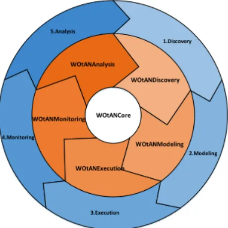
Figure 5.1: WOtAN Modules Integrated in BPM Lifecycle
5 Concepts and Architecture
A process engine is a very complex technology [33]. To handle this complexity, WOtAN consists of fivemodulesconnected by one common core, shown in Figure 5.1, called WOtANCore. Each module represents one step in theprocess model lifecycle[34]. The five modules are(NF_2):
1. WOtANDiscovery: Responsible for process discovery i.e., finding existing process modeles in companies.
2. WOtANModeling: Responsible for modeling of new process modeles or introducing ad-hoc manipulations of existing process modeles.
3. WOtANExecution: Responsible for process execution.
4. WOtANMonitoring: Responsible for live monitoring of process instances.
5. WOtANAnalysis: Responsible for analyzing executed process modeles.
This thesis focuses on WOtANExecution and WOtANAnalysis. All modules can be used without any other module, but rely on the WOtANCore(NF_3), NF_4. However, some modules may be useless alone. For example, WOtANMonitoring monitors running process modeles. Therefore, WOtANExecution is needed to execute process modeles that can be monitored.
The WOtANCore can be seen as the common language of all modules. The latter consists of high level data- and control-layer interfaces, enabling object-based intercom- munication between all modules(NF_5, NF_7).
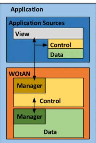
The general architecture of each WOtAN module is 3-Tier, consisting of a data- and a control-layer, shown in Figure 5.2. The view-layer is not needed in the engine itself, but the WOtAN using application. Each layer has a single entry point, calledmanager, for its respective upper layer, defined by a WOtANCore interface. WOtANCore provides for each module a correspondingdataandcontrol manager, e.g., for WOtANExecution this is theexecution manager. Every action called on a layer should be done over its manager interface.
A data manager is responsible for storing, deleting and fetching the respective data. Be- cause the data manager itself as well as the objects exchanged are based on interfaces,
24
5.2 WOtANExecution
WOtAN Application
Control Manager
Data Manager Application Sources
View
Control Data
Figure 5.2: WOtAN 3-Tier Architecture
the underlying data structure can be exchanged without any upper layer changes. The same principle of using interfaces is used in the control-layer as well.
This architecture enables the almost unlimited mixing of all WOtAN modules in one application. For example, WOtANExecution and WOtANAnalysis can be combined to enable a smart mobile application to execute and later analyze business process instances. Another useful combination could be to integrate WOtANModeling and WOtANExecution, whereas WOtANExecution works astest client for newly modeled process modeles.
5.2 WOtANExecution
As mentioned in Section 5.1, WOtANExecution enables applications to execute process modeles in a flexible and robust way. The following section describes the architecture of WOtANExecution. Subsection 5.2.1 introduces the concept of WOtANExecution.
Afterwards, Subsection 5.2.2 shows the WOtANExecution specific architecture.
5 Concepts and Architecture
5.2.1 Concepts Process Model
A process model is a graph-based description of a business process. It consists of different elements shown in Figure 5.3:
Start A End
B
C D E
D1
Node
Control Edge Data
Edge Data
Element
Figure 5.3: Process Model Example
• Node: A node is a step within the process model. It can have differentnode types, describing the semantics (e.g., gateway, normal, start, end).
• Control Edge: A control edge is an unidirectional edge, describing the order of execution between two nodes, e.g., D→E meaningD must be executedbeforeE can start.
• Data Element: A data element is a variable storing data for a respective instance of the process model. It may be read or written by nodes.
• Data Edge: A data edge is an unidirectional edge, describing the behaviour between a data element and a node e.g., A→D1 meaningAwritesdata in D1or D1→B meaningBreadsdata from D1.
A node’s type specifies its behaviour at run time as well as the permitted number of incoming and outgoing control edges. Table 5.1 explains the possible node types.
26
5.2 WOtANExecution
Node Type Description
STARTFLOW Start point for the process model.
ENDFLOW End point for the process model.
NORMAL A normal process model task, doing process model tasks.
XOR Splits the control flow into multiple branches. Only one branch will be activated and executed at run time.
AND Splits the control flow into multiple branches. All branches will be acti- vated and executed.
LOOP Allows to jump back at an earlier point of the control flow to execute parts of the process model model again.
Table 5.1: Node Types [23]
The node typesXOR,ANDandLOOPare divided into aJOINand aSPLITsubtype. The split and join node automatically generates a block, with the splitting node as entry point, and the joining node as exit point [35].
Process Model Execution
process model execution means traversing the process model graph, performing all nodes on the way, from start to end. To assure a proper and valid process model execution (according to the modeled control flow), the nodes are assigned to different node states. All node states and their possible transitions are shown in Figure 5.4. First, a node is in stateNOT_ACTIVATED.
When either the node’s preconditions are met, the node is set to state ACTIVATED.
During this node state, the engine can start a node changing its node state toSTARTED executing this step. Afterwards, the node gets terminated as either successful executed (COMPLETED), or executed with errors (FAILED). Subsequently, all following nodes are tested for activation.
5 Concepts and Architecture
When starting a new process model instance, the node with node typeSTARTFLOWis setACTIVATED, thus can be started from the engine. After reaching the node with node typeENDFLOW, the execution is considered (successfully) finished.
The node statesSELECTEDandSKIPPEDare not used for execution behaviour, but as internal helper node states. Therefore, they are not explained at this point.
Figure 5.4: Node States Overview [25]
Executable Business Process
Anexecutable business process (EBP)is a software template that can be stored in nodes.
Its function can vary from a graphical user interface (e.g., a user form) to a complex automatic computation. An EBP uses its own parameters, which must be mapped at run time to the corresponding data elements of the stored-in node. Its execution begins when respective node is started.
28
5.2 WOtANExecution
5.2.2 Architecture
WOtANExecution has three managers to control process instances: anexecution man- ager, instance manager, and a runtime manager. The manager dependencies are shown in Figure 5.5. The following sections describe each manager and its tasks.
WOtANExecution Manager
Runtime Manager Instance
Manager Instance Manager Instance Manager
Runtime Manager
Figure 5.5: WOtANExecution Manager Hierarchy Overview
Execution Manager
The execution manager is the top manager of the control layer. It is responsible for the communication between the application and the engine i.e., all commands to the engine are passed to the execution manager. This should be the only manager ever used by an application developer. The main task of this manager is to distribute given commands to the correct instance manager and return a possible result back to the caller. Further, administration tasks like process import(F1), process deletion(F7), and process execution data export(F6a)are distributed to respective components.
Instance Manager
An instance manager is responsible for exactly one currently running business process instance. It is dynamically created by a execution manager when a new process model
5 Concepts and Architecture
manager takes care of all related workflow control i.e.,changing node states and instance states correctly(F_3a, F_3b). The instance manager has one runtime manager for controlling the executable business process used in respective process model instance.
Runtime Manager
The runtime manager is responsible for bidirectional communication between the engine and the EBP, shown in Figure 5.6(F_4a). Therefore, it uses an communication channel.
The runtime manager sends EBP control message such asstart,suspend,restart, finishto the EBP. Additionally, the manager receives messages from the EBP, e.g., saving data,EBP’s GUI.
App
EBP A WOtANExecution
Runtime Manager
Communicaion Channel EBP B
Figure 5.6: Runtime Manager to EBP Communication
As one can see, an EBP can be stored within a smart mobile application or be stored externally(F_4c, NF_8), as illustrated in Figure 5.7. This is possible because WOtANEx- ecution uses weakly referenced EBPs. Internally stored EBPs are only visible to the smart mobile application it inherits. In contrast, externally stored EBPs are visible and can be used by all smart mobile applications on the device that use WOtANExecution.
The drawback of internally stored EBPs is that a change in the EBP results in updating the whole smart mobile application the EBP is stored in. A change of externally stored
30
5.2 WOtANExecution
EBPs does not require the update of any smart mobile application(NF_9). However, on one hand, loading externally stored EBPs uses more computation power than the use of internal EBPs. On the other hand, by storing EBPs internally, a EBP may be stored twice in two separate smart mobile applications, thus increasing storage consumption.
AppA
WOtANExecution EBP 1
EBP 2 AppB
WOtANExecution
Figure 5.7: Coupling the Engine with Standalone EBPs
Manager Behaviour Example
An example behaviour of managers at runtime is shown in Figure 5.8. This example illustrates the start of a node, that inherits an EBP. The application which uses WOtAN propagates a start node command to the execution manager . The execution1
manager passes this command to the responsible instance manager. The instance2
manager, however, generates a new runtime manager and commands it to start the nodes EBP. Then, the runtime manager creates a new EBP object, and gets binded3
to it. Then, the runtime manager passes environment data to the EBP for complete4
initialization. Finally, the runtime manager starts the EBP with its5 executecommand . Now, that the EBP is running, the application can ask for the EBP’s graphical user6
interface via execution managersgetGUIcommand, traversing the manager stack7
downwards to the EBP. Note that all commands are always passed down the manager stack to the responsible manager.
5 Concepts and Architecture
WOtANExecution
App Execution
Manager
Runtime Manager
Factory Instance Manager
EBP
startNode: 1 startNode: 2
startEBP: 3
createEBP: 4
Execute: 9
Create: 5
Bind: 6 setEnv: 8
getNodeGUI:10
1 2
3
4 5
7
6
Figure 5.8: Start Node Example
5.3 WOtANAnalysis
The WOtANAnalysis module enables applications to evaluate process modeles executed using WOtANExecution based on predefined rules. The first section describes concepts used, whereas the second section describes WOtANAnalysis’ architecture in more detail.
5.3.1 Concepts Rule
The concept of rules are adopted from [36]. Thereby, a rule consists ofcomparisons connected withBoolean ANDorOR. A comparison consists of two operandsand a Boolean operator. Operands can be pre-set values, variables, or functions. A function describes a specific behavior at evaluation time. Figure 5.9 illustrates a simple rule.
32
5.3 WOtANAnalysis
Figure 5.9: Rule Example [36]
5.3.2 Architecture
WOtANAnalysis consists of arule manager, a rule formatter, a rule importer, and a rule evaluator component. The following sections describe their tasks and behaviour, illustrated in Figure 5.10.
WOtANAnalysis
WOtANExecution Process Execution
Data
Rule Manager
Rule(s) Evaluation
Report Rule
Importer
1 2 3 4
Rule Functions Rule Formatter
Rule Evaluator
Figure 5.10: Rule Evaluation Overview
Rule Manager
The rule manager is WOtANAnalysis’ control manager. Therefore, it is the entry point for every application developer to use WOtANAnalysis. Its task is to orchestrate the rule
5 Concepts and Architecture
evaluation process by distributing all evaluation tasks in correct order to the responsible components.
Rule Importer
The rule importer is the first step in the rule evaluation process. The importer imports a given rule1 (F_8). The source of a rule can be, for example, a file or web-service. Note, that a rule importer must be specifically built for a given external rule format. Therefore, the importer must first create an object structure of the imported rule format, then call the respective rule formatter to transform the rule into the persistence format used.2
Rule Formatter
The rule formatter is, as the name suggests, a formatting component. It is called after the import of a rule by rule importer, but before persistence of respective rule. Like the rule importer, a rule formatter must be implemented for each external rule format that shall be importable.
Rule Evaluator
The rule evaluator is responsible for evaluation3 i.e., testing rules on given process execution data(F_9), generated by WOtANExecution, and create an evaluation report as answer4 (F_11a). The evaluation report includes the result, the tested rule, and other meta information likeidandnameof the process model instance that generated the process execution data(F_11b).
As described in Section 5.3.1, a rule can have functions in it(F10a). The function’s implementation is stored externally and will be dynamically loaded by the rule evaluator at runtime if required(F_10b).
34
6
Implementation Aspects
This chapter describes some technical aspects as well as design choices regarding WOtAN’s implementation. Section 6.1 explains the design philosophy behind the in- terfaces. Subsequently, Section 6.2 shows EBP implementation aspects. Following, Section 6.3 introduces the library used for object-relational mapping. Finally, Section 6.4 presents the rule evaluation implementation.
6.1 Interface Design
To ensure a modular and flexible architecture, all functions of any module are offered through interfaces. Hence, a developer works on interfaces of the respective modules.
This allows to switch implementations without any changes in the application’s code.
Therefore, interfaces are an important aspect of WOtAN.
Taking the limited data types passable to an AndroidBundlein account , all interfaces shown to application developers uses primitive data types and Java’s UUID class as parameters only. The following code shows method examples of the execution manager interface:
1 p ub li c i n t e r f a c e ExecutionManager {
2 p ub li c void s t a r t N o d e ( UUID modelId , Long nodeId ) ;
3 p ub li c ProcessModel getProcessModel ( UUID modelId ) ;
4 . . . }
Listing 6.1: Excerpt from Interface Methods
Instead of passing an object, only their identifiers are passed. As a result, aBundlecan
6 Implementation Aspects
most likely cached in the data manager and , therefore, quickly reloaded. Additionally, object loading can be skipped if no further information is required.
As one can see at method getProcessModel, return types can be objects. Alike methods are called after changing to another AndroidActivityor inside a new An- droidFragment. Further, one can see the rather high level API approach at method startNode(), which reduces the starting of a specifiedNodeto just one method call.
6.2 Executable Business Process Management
This Section gives an overview over EBP specific aspects of implementation. First, Sec- tion 6.2.1 describes the general structure for every EBP. Then, Section 6.2.2, introduces dynamic EBP loading at runtime. Finally, Section 6.2.3 describes challenges which need to be considered by EBP developers.
6.2.1 Structure
An EBP is developed as an Android application, weakly coupled to WOtAN by referencing WOtANCore. However, this application does not have any Android Activityin its Manifest. Despite the fact that the EBP is installed on the Android smart mobile device as a normal application, it cannot be launched by the Android Launcher and isinvisiblein the application overview. The reason for installing EBPs is to use its resource files (e.g., predefined String values, images, layouts). Furthermore, installation routines makes storing EBPs easier, because there is no need to manage an EBP repository.
As in Figure 6.1, EBPs should extend fromAbstractExecutableBusinessProcess, which is an Android Fragmentand implements ExecutableBusinessProcess in- terface. This way, the EBP developer can focus on semantic implementation, instead of thinking about infrastructural belongings.
36
6.2 Executable Business Process Management
AbstractExecutableBusinessProcess
+ ContextedLayoutInflater + EngineContext + EBPContext
Fragment
<<extends>>
MyEBP -mitgliedsName -mitgliedsName
<<extends>>
ExecutableBusinessProcess
<<interface>>
Figure 6.1: EBP Overview
6.2.2 Loading at Runtime
Because all EBPs are stored outside the main application’s sources, they need to be loaded at runtime. To do so, Android offers a DexClassLoader to loadjar orapk (android application) files. The code in Listing 6.2 describes, how an EBP can be dynamically loaded at runtime:
1 / / Create DexClassLoader
2 DexClassLoader d l =newDexClassLoader ( dexPath , optOutPath , 3 n u l l, t h i s. g e t C l a s s ( ) . g e t C l a s s L o a d e r ( ) ) ;
4
5 / / Load EBP from g i v e n c l a s s path and c a s t t o i n t e r f a c e
6 ExecutableBusinessProcess newEBP =
7 ( ExecutableBusinessProcess ) d l . l o a d C l a s s ( c l a s s P a t h )
8 . newInstance ( ) ;
Listing 6.2: Loading EBPs dynamically at Runtime
Line 2 instantiate a new DexClassLoader for the respectivejarorapkfile, that inherits the sources of the requested EBP with following parameters [37]:
• dexPath: One or multiple file paths tojarorapkfiles with demanded classes.
• optimizedDirectory: File path to a folder, where theDexClassLoadercan store optimizeddexfiles (optOutPath).
• libraryPath: List of native library directories (nullin the example)
• parent: The parentClassLoader(this.getClass().getClassLoader())
6 Implementation Aspects
After creation, aDexClassLoaderis used like any other Java class loader. Line 7 and 8 show the loading of a class and instantiation of an object.
For an EBP to be usable, several requirements have to be satisfied:
1. The android applicationpackage nameof the EBP must be equal to the package path of the EBP’s main class.
2. The node using the EBP must specify the correct implementation class path.
3. The EBP application must be installed on the Android smart mobile device.
4. The EBP main class must either extendAbstractExecutableBusinessProcess or implementExecutableBusinessProcess.
A small example: Letcom.example.TestEBPbe the full qualified name for the EBP main class. Hence, the node in the process model must have storedcom.example.TestEBP in itsimplementationClassattribute. However, the EBP application’s package name is onlycom.example.
A fully commented version of EBP loading source code in A.1 exemplarily shows the whole process of loading an EBP and illustrates the need for given conventions.
6.2.3 Development Challenges
Since EBPs are normal Android applications, they have their ownContext. Therefore, an EBP developer has to deal with two contexts: theEBP contextand theengine context. The EBP context must be used to access resources of the EBP, like layouts, strings, or images. Trying to use the engine context for accessing EBP resources may end in retrieving the wrong resource or an exception. Therefore, it is essential to use aLayoutInflaterwith the respectiveEBP context, so references on resources in XML layout files are correctly resolved. In contrast, theengine contextmust be used for runtime information (e.g.,Locale, andTheme). Further, theengine context is used to addFragmentsto the current runningActivity.
38
6.3 Object-Relational Mapping
TheAbstractExecutableBusinessProcessclass provides static access to both Android Context as well as a LyoutInflater with the correct Context. How- ever, if custom XML tags are used in layout files (e.g., from android support libraries), a LayoutInflaterFactory must be implemented and added to the predefined LayoutInflater. Otherwise, theLayoutInflatercannot load the classes mapped to these tags. An example factory is shown in Source A.2. Figure 6.2 illustrates the problem. The GUI classes of an EBP for its custom made XML tags in layout files are loaded with the respective DexClassloader. However, the LayoutInflater was loaded by another Classloader. As a result, the LayoutInflater cannot load the required classes, because its Classloadercan not access them. In contrast, a LayoutInflaterFactory loaded by the respectiveDexClassloaderhas access to the required classes.
Bootstrap Classloader
Classloader Classloader Classloader
Dex Classloader
LayoutInflater
EBP specific GUI Classes parent of
loads
Factory
access no access
Figure 6.2: Problem of Classloaders
6.3 Object-Relational Mapping
GreenDAO is an open source object relational mapper project, initialized by greenrobot [15]. It uses Android’s built-in SQLite database, mapping its tables to common Java objects.
6 Implementation Aspects
Figure 6.3: GreenDAO Overview [15]
6.3.1 Schema Generation
GreenDao lets the developerprogramtheir database tables, i.e., the application devel- oper has to write a Java program, that describes the database tables of A.3 [38]. The meta model used for generation is based on database table structure of Figure 6.4.
Figure 6.4: GreenDAO Meta Model [38]
The generator automatically creates POJO and DAO classes, as well as a database table manager class. Further, the greenDAO Core Lib must be imported into the Android application. All actors are shown in Figure 6.5.
6.3.2 Database Communication
The database can be accessed in 3 different ways [40]:
1. Direct DAO access: Calling aload()method from a responsible DAO object.
2. QueryBuilder queries: Create a query using the providedQueryBuilder.
3. Raw queries: Write a highly customized SQLite query asjava.lang.String.
40
6.3 Object-Relational Mapping
Figure 6.5: GreenDAO Generation Actors [39]
Source A.4 shows all 3 access types. Note that a DAO is only available through the generatedDaoSessionclass.
6 Implementation Aspects
6.4 Rule Evaluation Process
The rule evaluation process is performed byApache Commons JEXL. The latter stands forJava Expression Language, and is a scripting language, inspired by Apache Velocity and the Expression Language defined in the Java Server Pages Standard Tag Library version 1.1 (JSTL) and Java Server Pages version 2.0 (JSP) [41]. This Section describes the use of the JEXL library and describes how it is embedded into the process of evaluating rules during runtime. Section 6.4.1 illustrates the general use of JEXL, whereas Section 6.4.2 applies JEXL specifically to the Rule Evaluation Process.
6.4.1 General Usage
Generally, JEXL has three actors for scripting actions, shown in Figure 6.6 [42]:
• JexlEngine: The main protagonist, processing the passed Script or Expression.
• JexlContext: A context for the JexlEngine, most likely a key-value store.
• Expression/Script: The script to be processed by JexlEngine. Essentially, a Script consists of multiple Expressions. Expressions are written in a JEXL specific Syntax, described in [43].
JexlEngine Expression
JexlContext
Result optional
Figure 6.6: JEXL Actors
JexlEngine
Mapped Expression '(34 == 45 && false ==
false) || hello world .length() < 5'
JexlContext
Key Value
integerA 34 booleanA false stringB hello world Expression '(integerA == 45 && booleanA ==
false) || stringB.length() < 5'
evaluate() Result false Expression
'(integerA == 45 && booleanA ==
false) || stringB.length() < 5'
Figure 6.7: JEXL Processing Example
42
6.4 Rule Evaluation Process
TheJexlContextand anExpressionare passed to theJexlEngine, which then processes the Expression, returning a possible result for the given input. The fol- lowing example shows the whole process of JEXL processing in Figure 6.7. Let the Expressionbe:
1 ( i n t e g e r A == 45 \ & \ & booleanA == f a l s e) | | s t r i n g B . l e n g t h ( ) < 5
Further, following key-value pairs are stored within theJexlContext:
1 ( i n t e g e r A , 34)
2 ( booleanA , f a l s e)
3 ( s t r i n g B , ’ h e l l o w o r l d ’ )
First, JEXL recognizes variables in the givenExpressionand substitutes them with the respective value in givenJexlContext. In the given example, substitutingintegerA with34, booleanAwith false and stringBwith ’hello world’. Afterwards, it processes the givenExpressionwhich, in this case, is a Boolean expression. There- fore, JexlEngine evaluates it automatically and returnsfalseas the result. Note that JexlEngine calls thelength()method ofjava.lang.String. However, calling class methods is not restricted to strings. As a matter of fact, JEXL can call any available method from any class, as long as a object reference is stored in theJexlContext, granted that key andExpressionvariable match [42].
6.4.2 Rule Evaluation
This Section applies the introduced library from Section 6.4.1 to the Rule Evaluation Process. Therefore, the overall process of rule evaluation is described. Subsequently, the usage of rule functions is outlined.
Evaluation Process
For the rule evaluation process, illustrated in Figure 6.8, several data is required:
• Execution Logs: Log of the executed process instance, describing the order of execution, along with other data (e.g., timestamps).
6 Implementation Aspects
• Data Values: All values for data elements ever written for a given process instance.
• Data Elements: The data elements involved in this process instance.
• Rule Condition: The rule condition (e.g., expression) to be tested.
• Rule Functions: Functions, that may be used when testing the condition.
A rule condition is a JEXL string as described in Section 6.4.1. However, two require- ments must be met: First, variables must be named after their data element. Second, if a function is used, the variable name before the function name must be the full qualified name of the class implementing this function.
Because of the multiple occurrences of data values for one data element, only the latest values are stored in the JexlContext.
JexlContext Execution Logs Data Values
Data Elements
JexlEngine
Rule Repository
Rule Function
Rule Function
Rule
Function Load and
Instantiate
Parameter Parameter
Evaluation Result evaluate()
Figure 6.8: Rule Evaluation Process Overview
When evaluating a rule, the rule condition and JexlContext are given to the JexlEngine.
The result of of the evaluation is aBoolean. ThisBoolean, combined with the evaluated rule and other process instance information is wrapped in an EvaluationReport, which is returned to the caller.
44
6.4 Rule Evaluation Process
Rule Functions
WOtANAnalysis uses rule functions for analysis. These functions are implemented in Java, translating every function in a Java method. WOtAN provides an abstract class for rule function development, namedAbstractRuleOperation. It provides a common constructor for all classes that may receive the execution logs, data values, and data elements passed. This data is needed for dynamically loading these type of classes at runtime with a DexClassLoader, as described in 6.2.2.
However, these classes are stored within an external repository, as one can see in Figure 6.8 and are not installed as standalone Android applications. Therefore, to find the correct class at runtime, the name of the jar file must be the same as the full qualified name of the implementing class. To find the relevant function classes for each rule, every rule has adependencyattribute, declaring a list of full qualified class names. The loaded classes are instantiated as an object, and set in the JexlContext. Note that the full qualified class name is used as key. The functions are now visible to JEXL and ready to use.
![Figure 2.4: Node States Chart [25]](https://thumb-eu.123doks.com/thumbv2/1library_info/5209122.1668791/22.892.309.674.372.647/figure-node-states-chart.webp)
![Figure 3.1: jBPM Overview [29]](https://thumb-eu.123doks.com/thumbv2/1library_info/5209122.1668791/25.892.278.526.786.944/figure-jbpm-overview.webp)
![Figure 3.2: General MAPRLE Architecture [31]](https://thumb-eu.123doks.com/thumbv2/1library_info/5209122.1668791/26.892.304.677.679.848/figure-general-maprle-architecture.webp)