https://doi.org/10.1007/s10270-020-00785-7 S P E C I A L S E C T I O N P A P E R
IoT meets BPM: a bidirectional communication architecture for IoT-aware process execution
Stefan Schönig1·Lars Ackermann2·Stefan Jablonski2·Andreas Ermer3
Received: 29 October 2018 / Revised: 31 October 2019 / Accepted: 21 February 2020 / Published online: 19 March 2020
© The Author(s) 2020
Abstract
Business processes are frequently executed within application systems that involve humans, computer systems as well as objects of the Internet of Things (IoT). Nevertheless, the usage of IoT technology for system supported process execution is still constrained by the absence of a common system architecture that manages the communication between both worlds.
In this paper, we introduce an integrated approach for IoT-aware business process execution that exploits IoT for BPM by providing IoT data in a process-compatible way, providing an IoT data provenance framework, considering IoT data for interaction in a pre-defined process model, and providing wearable user interfaces with context-specific IoT data provision.
The approach has been implemented on top of contemporary BPM modeling concepts and system technology. The introduced technique has evaluated extensively in different use cases in industry.
Keywords Process Execution·Internet of Things·Wearables
1 Introduction
Business process management (BPM) is considered as pow- erful technology to operate, control, design, document, and improve cooperative processes [1]. Processes are exe- cuted within application systems that are part of the real world involving humans, cooperative computer systems as well as physical objects [2]. Internet of Things (IoT) as well as cyber-physical systems (CPS), denoting the inter- networking of all kinds of physical devices, have become very popular these days [3–6]. Data sets grow rapidly, in part because they are increasingly gathered by cheap and
B
Stefan Schönig stefan.schoenig@ur.de Lars Ackermannlars.ackermann@uni-bayreuth.de Stefan Jablonski
stefan.jablonski@uni-bayreuth.de Andreas Ermer
aermer@maxsyma.de
1 Institute of Management Information Systems, University of Regensburg, Regensburg, Germany
2 Institute for Computer Science, University of Bayreuth, Bayreuth, Germany
3 Maxsyma GmbH & Co. KG, Floß, Germany
numerous information-sensing IoT devices such as mobile devices, aerial (remote sensing), software logs, cameras, microphones, radio-frequency identification (RFID) readers, and wireless sensor networks. Therefore, IoT contributes to the recent trend known as big data. Handling big data requires techniques with new forms of integration to reveal insights from datasets that are diverse, complex, and of a massive scale [7–9].
Process execution, monitoring and analytics based on IoT big data can enable a more comprehensive view on processes.
Embedding intelligence by way of real-time data gathering from devices and sensors and consuming them through BPM technology helps businesses to achieve cost savings and effi- ciency.
Let us consider a production process where raw material is processed by different machines under the supervision of human operators. In case of product quality issues, manual human interventions are necessary. Additionally, operators must be aware of current sensor data to decide on tasks to be executed next. Such a scenario might be better manageable when closely linking digital production and machine data, such as regularly available in typical Industry 4.0 [10,11]
scenarios, with human operators as enabled by the integration of IoT and BPM. Here, human activities can be triggered by a BPM engine through intermediate reactions to appropriate IoT real-time data in the underlying process model. Human
operators can be notified seamlessly without loss of time on wearable devices while leveraging current context-specific information. As a consequence, the integration of IoT and BPM technology could lead to efficiency gains by reducing reaction time and enhance the quality of task execution.
In the literature, several concepts are emerging on combin- ing IoT and BPM, e.g., monitoring running processes to align them with the state of physical devices and objects [12–15].
Still, there are many open challenges to be tackled [16–18].
In particular, the exploitation of IoT technology for system supported process execution is constrained by the absence of a common architecture that manages and standardizes the communication between both worlds.
In this paper, we present an approach that combines the recording and analysis of IoT and sensor data with the tech- nology of process management. Here, our aim is to build the developed integration on top of existing BPM concepts and technical solutions. In summary, we propose an inte- grated approach for IoT-aware business process execution that exploits IoT for BPM by (i) providing IoT data in a process-compatible way, (ii) providing an IoT data prove- nance framework, (iii) considering IoT data for interaction in a pre-defined process model, and (iv) providing wear- able user interfaces with context-specific IoT data provision.
The approach has been implemented and evaluated exten- sively in different industry scenarios. The results show that the application of IoT-enhanced BPM leads to less machine stops because operators need less time to recognize work to be done. Furthermore, the use cases successfully highlight the bidirectional communication capabilities of the presented architecture.
This article is an extension of conference publication [19].
It extends the original article in various ways:
(i) the concepts have been extended in different directions, a.o. several possibilities to bridge the abstraction gap between IoT and BPM and, in particular, several pos- sibilities to actively interact with IoT objects based on standard BPM technology.
(ii) the implemented software is presented in much more detail.
(iii) the related work section has been extended and dis- cussed more thoroughly.
(iv) the evaluation section has been extended significantly toward the presentation and discussion of several appli- cation use cases.
This paper is structured as follows: Sect. 2 describes research background and fundamentals. Section3gives an overview of related work. Section4introduces the approach for a IoT-aware process execution that takes into account both passive information provision as well as active interac- tion possibilities. In Sect.5, we describe the implementation
of our approach based on well-known communication pro- tocols. In Sect. 6, we evaluate our approach with several extensive application use cases in different fields of industry and Sect.7finally concludes the paper.
2 Research background and fundamentals
The Internet of Things (IoT) is the inter-networking of phys- ical objects like (i) electronic hardware, e.g., sensors and actuators or (ii) humans using wearable digital devices like glasses and smartwatches [3,6,20]. Such connected things collect and exchange data between each other. IoT allows things to be controlled remotely across existing network infrastructures, including the Internet [6,21]. A business process is a collection of related events, activities, and deci- sions that involve a number of (human) resources [1]. To support processes at an operational level, a business pro- cess management system (BPMS) can be used. During process execution, a variety of information is required to make meaningful decisions. With the emergence of IoT, data are generated from physical devices sensing their (busi- ness/manufacturing) environment that reflects certain aspects of operative processes. A BPMS deals, a.o., with the enact- ment of process models that define the interplay between environmental circumstances (depicted as data values), char- acteristics of participants (depicted as resource assignments) and corresponding activities to be executed. We consider processes as explicit process representations (pre-defined models), which later are enacted.
2.1 Research problem
Recently, several researchers raised specific research chal- lenges that need to be tackled in order to align IoT and BPM technology [16]. In this section, we explain a specific subset of those challenges that is tackled by the integration of IoT objects and a BPMS as it is described in the work at hand.
First of all, IoT sensors need to be placed in a process- aware way in order to be able to collect and record all process relevant IoT data. Therefore, sensors need to be carefully placed at machinery and humans and be digitally accessible.
The acquired process relevant IoT information needs to be up to date and current. It needs to be clear where the data stem from and where it has been used (cf.data provenance), as well as the quality of the data at hand needs to be ensured.
It becomes necessary to find a way to annotate the IoT data origin and to use this (meta-)information in business process models.
Second, in many processes some activities require the interplay between human operators and software/hardware modules. There is an increasing use of mobile devices fos- tering the delivery of work items to the right users. Here,
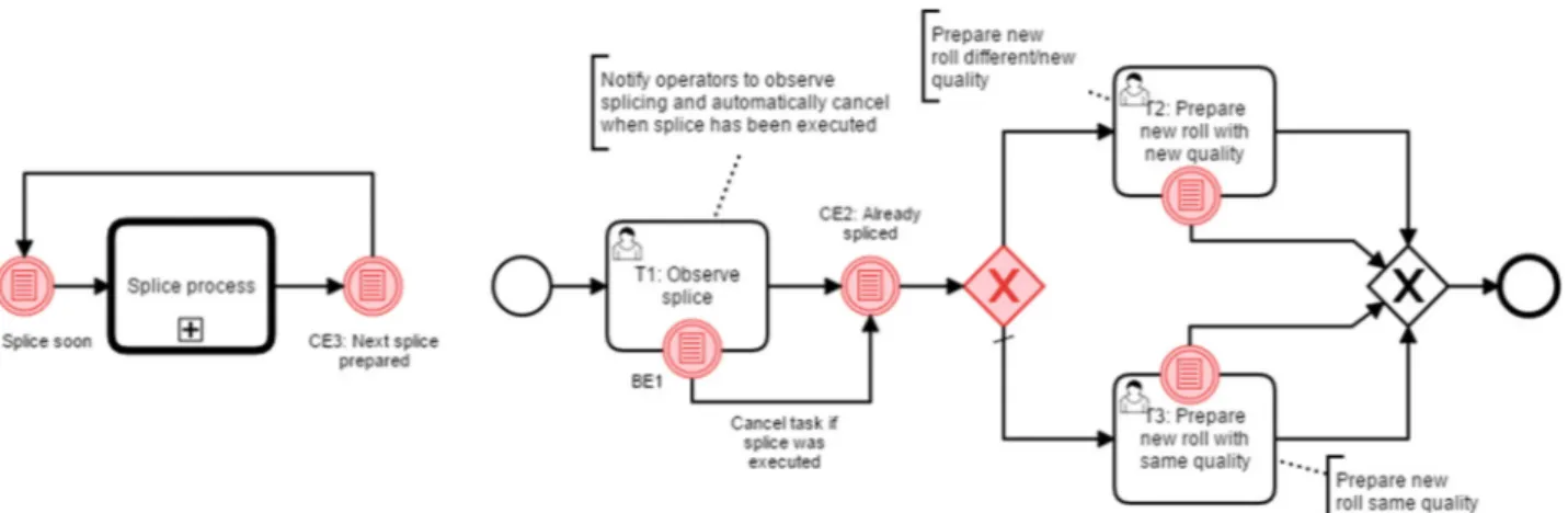
Fig. 1 Exemplary production process:arepeating subprocess;bsplice process
an appropriate mapping from activities to user interfaces is needed allowing process participants to perform their work from arbitrary places in the working environment.
Third, participants might suffer from issues which hin- der optimal working conditions. Here, the IoT can support the execution of tasks in a process through context-specific knowledge provisioning that is relevant for the users partic- ular context. Sensor data can be leveraged to determine the actual context and to identify information needs.
These three challenges constitute the basis for the research of the work at hand. Accordingly, the underlying research question ishow to design a BPMS within an IoT environ- ment such that IoT devices like sensors and mobile devices are enabled to foster process execution in manifold terms like quality of task execution or reduction of delays. We tackle these open research gaps by conceptually designing and implementing a common technical architecture for IoT- aware business process support. Sensing and perception the process environment via sensors constitutes the fundamen- tal task of the IoT. Sensor data then must be aggregated, interpreted, and made available to the BPMS in order to trig- ger business process activities or human tasks, respectively.
These tasks and corresponding context information must then be send in real time to responsible individuals that receive tasks on mobile user interfaces.
2.2 Motivating example
Additionally, we want to motivate the necessity of our approach by example of a real-life process from production industry that is visualized in Fig.1. The example stems from the corrugation area where paper is glued to corrugated paper that depicts the basis for cardboard boxes. The example pro- cess is explained in detail in Sect.6.1. The given example is a subprocess that is executed every time paper source rolls run empty, i.e., where new paper rolls need to be spliced with the paper from the low running roll. In order to effectively
execute this process, several real-time interactions with IoT devices, i.e., sensors and operator equipment, are necessary:
The BPMS must be aware of sensor data which indicates that a splice will happen soon, triggering the splice subprocess.
Operators located somewhere along the up to 300 meters long machinery need to observe the splice process to avoid issues. Therefore, they need to be notified in real time to walk to the splicer. This requires wearable interfaces com- municating with the BPMS over the IoT. Depending on a sensor value indicating the next roll quality, the BPMS has to execute different paths. In case the environment changes, operators tasks need to be reordered based on priorities or canceled by the BPMS. In addition to current tasks to be executed, operators require context-specific information at hand, e.g., the location of the splicer and the quality of the next paper roll. Furthermore, operators continuously need to observe viscosity and temperature of the glue to ensure a successful splice process. In the following sections, we show that the integration of IoT devices and a BPMS serves as a generalizable solution to the problems above.
2.3 Research method
This work is based on theDesign Science Research(DSR) approach [22], which was adapted to the needs of this work.
This approach is meant to solve identified problems in a build-and-evaluate process in order to create fitting informa- tion technology artifacts [23]. The hereby created artifacts are meant to be of relevance to a human purpose. The goal of creating and evaluating artifacts is to derive generalizable and transferable knowledge.
Typically, the DSR approach follows six iterative steps [24]: Initially, the problem needs to be identified and its importance needs to be shown (1). Second, objects of a solu- tion are defined (2), and based on these objectives, the artifact is designed and developed in the third step (3). In the fourth step, the artifacts functionality is demonstrated (4) before
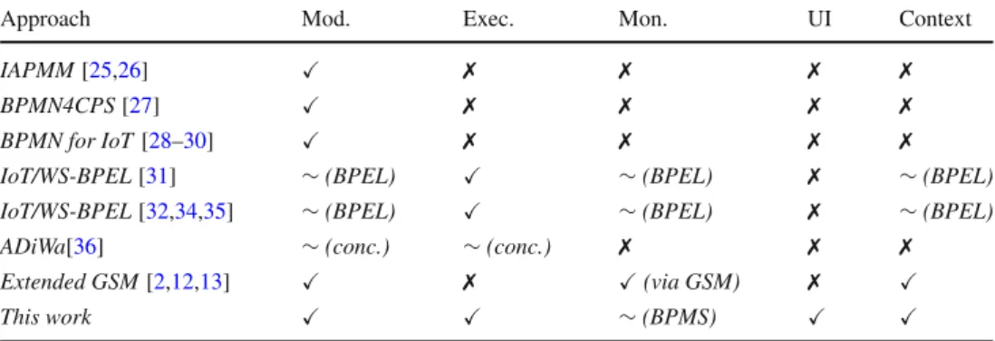
Table 1 Overview on related approaches of the integration of IoT and BPM
Approach Mod. Exec. Mon. UI Context
IAPMM[25,26] ✗ ✗ ✗ ✗
BPMN4CPS[27] ✗ ✗ ✗ ✗
BPMN for IoT[28–30] ✗ ✗ ✗ ✗
IoT/WS-BPEL[31] ∼(BPEL) ∼(BPEL) ✗ ∼(BPEL)
IoT/WS-BPEL[32,34,35] ∼(BPEL) ∼(BPEL) ✗ ∼(BPEL)
ADiWa[36] ∼(conc.) ∼(conc.) ✗ ✗ ✗
Extended GSM[2,12,13] ✗ (via GSM) ✗
This work ∼(BPMS)
it gets evaluated (5), determined by the evaluation criteria and objectives of step two. Therefore, different evaluation approaches depending on the specific use case are possi- ble [23]. Finally, the results are communicated and published (6).
We strictly followed the above-described iterative steps in the work at hand. In the first step, we identified significant needs for combining IoT and BPM technology. This has been shown by concrete challenges defined by the current scien- tific literature (cf. Sect.2.1) as well as by means of a concrete example scenario (cf. Sect.2.2) (1). In the second step, we derive specific design objectives that our IoT-aware process architecture needs to fulfill (2). These objectives determine the functionality and design of the prototype (3) that are pre- sented in Sect.4 and implemented in Sect. 5 of the work at hand. We demonstrated the functionality of our prototype in several, extensive real-life use cases (4). We conducted an evaluation in terms of usability studies and performance improvements (5). Finally, we conducted step six by pre- senting our results on several conferences and submitting this manuscript.
We also met the requirements of DSR as an iterative pro- cess [24] where we not only conducted rapid prototyping of the system, but also presented intermediate results to the industry partners. Their input and knowledge were used to additionally refine our objectives and therefore the design and functionality of the system architecture.
3 Related work
Several approaches have been proposed to relate IoT objects with business processes. An overview of related approaches for IoT and BPM integration is given in Table1. The table summarizes the support of each approach for IoT-aware process modeling, execution, and monitoring as well as the availability of a mobile user interface and the possi- bility to provide (IoT) context information. In [25,26], the authors present the Internet-of-Things-Aware Process Mod- eling Method (IAPMM) that covers requirements analysis.
It extends the BPMN meta-model to model IoT-aware pro- cesses. The approach in [27] (BPMN4CPS) also describes an extension of BPMN in which the process logic is split into the cyber part, the controller, and the physical part. Further- more, the authors extended BPMN by new task types. Some more notation concepts in BPMN for IoT are described in [28–30]. The main focus is on the modeling of real-world properties. Also in [28,29] the authors present an exten- sion of BPMN with new modeling concepts. None of the described approaches provides details on how to execute these models. In [31], an approach for implementing an IoT-aware execution system given in WS-Business Process Execution Language (WS-BPEL) is introduced. It extends BPEL bycontext variableswhich are automatically updated.
The authors implemented a prototype which is compliant with every WS-BPEL engine. Other approaches implement- ing BPEL extensions are presented in [32,33]. The variables are updated using the publish/subscribe paradigm. Another extension for WS-BPEL (Context4BPEL) with features to manage context events to allow the asynchronous reception of events, query context data and evaluate transition condi- tions based on context data is described in [34]. In [35], the authors integrate distributed resources into WS-BPEL by for- malizing a fragment of WS-BPEL together with the WSRF (Web Services Resource Framework). In [36], the authors propose an approach for enabling IoT-based agile business processes. They provided concepts for extending models by triggers for variance. The approaches in [2,12,13] rely on the information coming from artifacts involved in the process to understand how a process evolves. By adopting an extension of Guard–Stage–Milestone (GSM), it is possible to moni- tor the process even when the control flow is not respected.
The work presented in [37] introduces a lightweight pro- cess engine for enabling mobile applications. The authors describe requirements and concepts for mobile process appli- cations and a prototypical mobile user interface. However, this work does not comprise IoT related aspects.
The work presented in [17] lists and reviews specific chal- lenges and opportunities to combine BPM and complex event processing (CEP) technology. These challenges are consid-
ered as the core issues of this combination. The authors suggest that addressing these issues would form a basis for future applications. Therefore, this work can be seen as a motivation for the article at hand.
In addition to the stream of research that integrates IoT and BPM concepts, the work at hand is related to research on (mobile) task assistance and decision support systems in production area, i.e., concepts and approaches related to the termIndustry 4.0 [10,38]. Here, sensors have the capabil- ity of measuring a multitude of parameters frequently and collecting plenty of data. Analysis of big data, both histor- ical and real time, can facilitate predictions on the basis of which proactive maintenance decision making can be per- formed [39,40]. The e-maintenance concept can significantly address these challenges. There are several research works that introduce intelligent agents that are directly implemented at the shop floor level [41]. Furthermore, there is research about web-based production maintenance services and archi- tectures that include wireless sensing of process data and identification technologies, data and services integration and interoperability [42]. Portable computing devices have been used for production monitoring for many years. Though initially offered as an integrated instrumentation solution, mobile devices such as PDAs and tablets have been pro- grammed with a mobile capacity to analyze and present data, disconnected from the actual sensing components [43,44].
These solutions introduce concepts, architectures and proto- typical implementations for configuring the sensing infras- tructure and for presenting certain process and equipment data on mobile devices. The work at hand, however, extends the described solutions by introducing an integrated sensor and process-based information system that is implemented on top of wearable operator interfaces.
4 Bidirectional architecture for an IoT-aware BPMS
Based on the three challenges defined in Sect.2.1, we can define requirements of the corresponding artifact that will be developed throughout this work.
We propose a four-steps procedure to provide the nec- essary information. The first step is connecting IoT objects and their values traceable to a BPMS. We call a single type of value of a certain (sensor) objectvariable. The second step is extending a BPMN process model with data variables partic- ipating in the process stemming from physical objects such as machine status or actor positions. The resulting process models must be applicable by default contemporary BPMN execution engines. This way, organizations can reuse existing process models, without having to learn new languages and remodel processes from scratch. The third step is to establish a real-time notification interface of triggered activities to pro-
cess participants by means of mobile devices. In the fourth step, context relevant information stemming from connected objects must be selected and provisioned to users.
Summing up, our approach focuses on the following open research gaps defined in the literature [16]:
– IoT sensors need to be placed in a process-aware way and be linked to running processes (C1).
– Mobile devices should be used, fostering the delivery of work items to the right users (C2).
– IoT should support the execution of tasks through context-specific knowledge provisioning (C3).
Based on these challenges, our approach poses the follow- ing four main requirements that can directly be linked to the challenges mentioned above:
R1. A BPMS must be aware of current values of IoT objects. (cf. C1) Variable attributes, e.g., address and identifiers, must be configurable and traceable, i.e., it must be clear where the data stems from. The acquisition of current values from diverse data variables with stan- dard IoT protocols must be possible. Here, erroneous data must be detected and excluded. Based on an established mapping from IoT variables to process models, IoT data must be sent to a BPMS.
R2. Each defined variable must be referenceable in the executed process model.(cf.C1) Based on current values of certain variable, tasks are triggered or canceled and decisions are made.
R3. Responsible users must be notified on mobile devices in real time. (cf. C2) Process participants must be seamlessly notified when human interaction is required, independent of where the user is located.
R4. Context-specific knowledge must be provisioned to users.(cf. C3) Alongside with activity notification, context-specific and process relevant information must be provisioned to users.
4.1 Connecting current data of IoT objects to BPMS In this section, we describe the necessary steps to connect the IoT objects and their current values to BPMS. Here, we focus on a variable mapping and discuss different methods to bridge the existing abstraction gap between IoT data and business processes.
4.1.1 Variable mapping
First, we formally define IoT object data that are regu- larly, i.e., in a certain interval i nt acquired from digi- tally accessible devices and stored in a IoT middleware
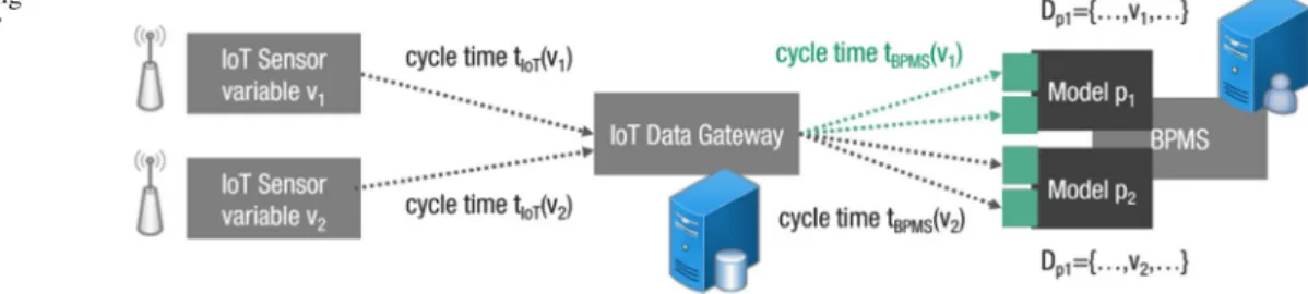
Fig. 2 Acquisition: mapping and connecting current IoT variables to BPMS
database. Data recorded from IoT objects are an ordered sequenceσ of eventsej, i.e.,σ =
e1, . . . ,e|σ|
. In gen- eral, an event e is defined as tupel of attributes-value pairs, i.e., e =
(at tr1e, val1e), . . . , (at tr|ee|, vale|e|) . The set of all attributes AT T Re and the corresponding values V ALe of an event e are therefore defined as AT T Re =
at tr1e, . . .,at tr|ee|
,V ALe=
val1e, . . ., v|ee|
. Eachat trie has an unique variable identifierv and a timestampti me, i.e.,∀e∈σ(ve,ti mee)⊆AT T Re. Each attributes-value pair (at trie, valie)is dedicated to exactly one IoT variable. With le(vie) = valie we denote the valuevalie of a certain vari- ablevie in evente. A total order of events is implemented as follows:∀1≤j<k≤|σ|(ti meej) < (ti meek). Therefore, the current value of a certain variablevi is given asle(vie|σ|)= valei|σ|. All other attributes are optional. Based on these def- initions, we ensure that IoT data variables are configurable and traceable (cf. R1). In the next step, current data of each connected IoT object must be sent to the BPMS (cf. R1).
Therefore, we need to map IoT data to enacted process mod- els of the BPMS. Consider a set of process modelsPwhere each p contains a set of data variables Dp. Each variable d∈ Dphas an unique identifiervd. The underlying assump- tion is that each participating IoT variable is referenced by the same unique identifier in the corresponding process model.
If we want to establish a connection between the data of an IoT object and a process variable, then both identifiers have to be the same, i.e.,vi = vdp. As visualized in Fig.2, IoT variablev1is semantically mapped to variablev1of process modelp1and IoT variablev2to variablev2of process model p2, respectively.
4.1.2 Bridging the abstraction gap
Having established such a semantic mapping, only current data of each connected object are sent to the BPMS, i.e., a sending procedure sp is initiated for each variablevie|σ|
recorded in e|σ| sending the latest acquired values to the BPMS, i.e.,∀1≤i≤|e|vei|σ|. The technical implementation of the connection is hereby established by means of a IoT infras- tructure. Here, it is frequently necessary to bridge a certain abstraction gap between partly high frequent IoT and sensor data and human activities of business processes. We outline three different possibilities to bridge the gap. Note that it is
Table 2 Example acquired IoT object data
Event at trie(v, . . . ,ti me) valei Data type
1 (R M1,. . ., 2018-01-09 10:15:32) 300 Historic
1 (QU,. . ., 2018-01-09 10:15:32) 211 C Historic
1 (GT,. . ., 2018-01-09 10:15:32) 120 Historic
2 (R M1,. . ., 2018-01-09 10:15:42) 133 Current
2 (QU,. . ., 2018-01-09 10:15:42) 211 C Current
2 (GT,. . ., 2018-01-09 10:15:42) 115 Current
only necessary to clearly mention the concepts, and all of them are ready for use in contemporary IoT platforms that are based on streaming environments like Apache Spark.,1 Apache Kafka2, etc.
Simple cycle time to cycle time method The simplest method is probably a simple cycle time to cycle time map- ping between the IoT world and the BPM world. Figure2 visualizes this mapping scheme by providing different cycle times. IoT data are gathered and stored with high frequency (cycleti meI oT) while the same value is delivered to a BPMS with lower frequency (cycleti meB P M S).
Example:Let us assume that we acquire data from a sen- sor indicating the restmeters of paper on a specific rollR M1, the quality of the paper roll to be used nextQU and the cur- rent glue temperatureGT from a temperature sensor in an intervali nt =10sec. The acquired IoT data are then exem- plarily given as shown in Table2. Consider a process modelp where two data variables are referenced and evaluated. These variables are defined asvdp1 =R M1andvdp2 =QU, respec- tively, in the model. The procedurespis initiated every 10 s. Therefore, the last execution ofspsends the values 133 and 211Cto the BPMS where these values are dedicated to the corresponding process variables{d1,d2} ∈Dp. Note that data referring toGT are not sent to the BPMS.
Condition and aggregation-based method A more sophis- ticated method to bridge the abstraction gap between both worlds is to introduce conditions, triggers and aggregations.
1 https://spark.apache.org/.
2 https://kafka.apache.org/.
Here, IoT data are only sent to a BPMS if certain conditions hold true. Note that these conditions must not be related to the IoT data only, and they can also refer to specific data value from other sources. Examples are, a.o., (i) IoT data are sent at a specific point of time, (ii) IoT data are sent if the current value is below a certain threshold, or (iii) IoT data are sent if a certain external variable is below a certain threshold. Con- sidering that a certain time elapsed between recording IoT data and the point of time where it was sent to the BPMS, it might be necessary to first calculate aggregations on the recorded data before sending the result to the BPMS.
Complex event processing-based method The most elabo- rate approach to bridge this gap is to make use of complex event processing methods [17]. Here, the simple condition- based method is replaced by a more complex technique where we look at recorded IoT data in more detail. A single data acquisition record is seen as aneventwhere each event has specific attributes, e.g., value or timestamp. In CEP, we can define patterns on these attributes that have to hold in order to trigger a sending procedure. Here, a potential pattern might be: sent IoT data to the BPMS if the considered sensor sends nvalues below thresholdxin a time windowt.
4.2 Enrichment of process models with IoT variables As described in Sect.4.1, we consider a set of process models Pwhere each pcontains a set of process variablesDpthat semantically correspond to a variable of an IoT object. Based on the established real-time connection described before, these IoT-aware process variables, identified byvdpi, can be referenced in enacted process models in various ways. We assume that a given process model p is defined as BPMN conform process diagram, one of the most used formalisms for process modeling, representing the IoT-aware process to be executed. A BPMN process diagram specifies which activ- ities are executed in a process as well as their control flow relationships. To be able to infer when activities start or end based on the state of the variables, the diagram must cap- ture this information (cf. R2). This step requires the process designer to enrich the given BPMN diagram by including information on how and where the connected IoT variables influence the process. Here, data of IoT variables can only be read, i.e.,passive, informingor be actively written, i.e., active, interacting.
4.2.1 Passive informing
When using IoT object data in business process models, we consider several possible interaction possibilities. The pos- sibilities described below can serve as a good starting point to understand the concepts and potentials of enacting IoT information in process models.
a. IoT-based trigger events Sometimes, we only want a process to start or to continue if a certain condition is true. In BPMN conditional events, define an event which is triggered if a given condition is evaluated to true. It can be used as an (i) Intermediate Conditional Event, as a (ii) Boundary Event or as a (iii) Conditional Start Event. In case of (i), current values of used IoT variablesvardpi trigger anIntermediate Catch Eventand the execution continues to the next activity.
In case of (ii), the BPMS checks whether the process environ- ments changed based on the current values of the connected IoT variables. If the given condition is satisfied, then the cor- responding activity will be interrupted.
Example:Consider the example process in Fig.1where the control flow reaches the conditional eventCE1and the condition is, for example,R M1<200. Given a current IoT sensor value ofvaleR M|σ|1 = 133, the condition will be satis- fied and the BPMS triggers the subprocessSplice process.
Similarly, if the splice has been executed successfully, i.e., valeR M|σ|1 >200, thenObserve spliceis aborted by means of the corresponding boundary eventBE1.
b. IoT-based decisionsIn BPMN, an data-based gateway is used to model a decision in the process. Similar to conditional events, current IoT variable values can be used to decide which sequence flow is selected for continuing the process.
Example:Depending on the next paper quality to be used in the production order, the BPMS has to decide how to con- tinue the process, i.e., based on the current value ofvaleQU|σ|
either taskT2or taskT3will be triggered.
c. IoT-based loopsIn order to model repeated behavioral patterns, IoT variables can be used to define event-driven loops. This way, end-to-end processes can be broken up into comprehensiblemicro-processes.
Example:In order to support the recurring splice process in Fig.1a, the subprocess is surrounded by the conditional eventsCE1andCE3. While the positive evaluation of the given conditions inCE1, i.e., splice happening soon, triggers the subprocess to be executed,CE3checks if all preparations for the next splice have been executed. In case the corre- sponding IoT stemming data values fulfill the given event condition, the process continuesCE1.
4.2.2 Active interaction
In order to establish a full-fledged integration between IoT objects and process management, it is necessary to also pro- vide an active interaction possibility, i.e., write access from a BPMS to IoT objects. As for the passive informing case, the BPMN language already provides several language elements that can be used to establish such a communication.Service Tasks are used to call (web) services or program code in general and are therefore a solution for defining automatable tasks. Contemporary BPMS is often already equipped with fully implemented connectors to established web communi-
Input:T: Set of available tasksT= t1, . . . ,t|T| Input:U: Set of registered usersU=
u1, . . . ,u|U| foreachu∈Udo
devi ceI d: identifier of mobile device dedicated tou tasksToSend← ∅
foreacht∈Tdo
ifuamong candidate users of tthen tasksToSend←tasksT oSend∪ {t}
iftasksT oSend>0then send T asks(devi ceI d)
Algorithm 1:Distributing assigned human tasks to wear- able devices
cation protocols like HTTP. On the other hand, IoT objects frequently provide open interfaces for protocols like HTTP such that a direct communication interface from BPMS to IoT object can be realized. However, also in application sce- narios where IoT objects are only accessible by means of different extrinsic protocols (a.o. TCP/IP, MQTT, etc.), it is possible to establish an integration. Here, we make use of diverse open-source programming tools for wiring together hardware devices like the Node-RED platform.3This way, e.g., a BPMS communicates via HTTP with a wiring plat- form that, in turn, handles the request and creates a message according to the target protocol of the IoT object.
4.3 Establishing the real-time mobile user interface It is important that process participants are seamlessly noti- fied when human interaction is required, independent of where the user is located. This requires a real-time noti- fication on mobile devices of responsible users (cf. R3).
Therefore, it is necessary to define a mapping of users to corresponding mobile devices that serve as wearable, user- specific process cockpits and task lists, respectively. This is achieved by specifying a dedicated mobile device identifier for each defined user in the BPMS. During process execution, the currently available tasks for a specific process partici- pant are then directly sent to the specified mobile device.
The algorithm to distribute the currently available human tasks to defined mobile devices is given in Algorithm1. The actual operator to device mapping and the task distribution is described in detail in Sect.5.
Example:The splice process in Fig.1b requires operators to manually observe the splice at the specific machinery (T1).
Therefore, in case the condition inCE1evaluates true, the responsive operator needs to be notified in real time to be able to walk to the splice site in time. Hence, as soon as task T1becomes available, the list of currently available tasks of assigned operators implemented as a smartwatch application is updated.
3https://nodered.org/.
4.4 Context-specific information provision
Alongside with activities, context-specific and process infor- mation must be provisioned to operators to improve the quality of task execution (cf. R4). In order to ensure that the provisioned information is of value for operators, the fol- lowing three dimensions need to be considered when defining data that should be delivered to certain process participants.
Based on these dimensions, Algorithm 2 distributes IoT information in a context aware way to corresponding users.
a. Dedicated Context—Which entities allow for a separate context definition?There are different entities where different contexts can be defined for. IoT variable information can be dedicated to subprocesses and delivered alongside with tasks of this subprocess to respective users. Furthermore, IoT vari- able data can be dedicated to specific user groups or roles.
Within a location-aware BPM scenario, the information con- text can also be defined based on locations.
b. Information/Source—Which IoT information should be provisioned?IoT data can be classified according to the fac- tors of the context framework defined in [45], i.e.,intrinsicor extrinsiccontext information. Intrinsic IoT variable informa- tion reflects data used in the process model and is therefore directly related to the currently executed process instance.
Extrinsic IoT data are information that is not necessarily related to a running processes but might influence process execution as well, e.g., production hall temperature. Further- more, the granularity of provisioned information must be adjustable w.r.t. different processes. In some cases, it might be helpful to see more information; in some cases, it might be better to see less information to prevent users from infor- mation overload.
c. Visualization—How is a certain context-specific IoT variable presented or visualized?Context-specific IoT infor- mation must be visualized in a proper way. Depending on the class of information (intrinsic, extrinsic) or the data type (string, number) different positions on the interface and rep- resentation styles are appropriate. Intrinsic, instance-specific information that is relevant for the execution of a certain activity can be represented as information below the activity name. Extrinsic, environmental data that might be of impor- tance to process execution can be represented as separate controls on additional tabs.
Example: In the splice process in Fig. 1b, a context is defined for specific groups of operators. Only the users assigned to group Wet-End will receive information w.r.t.
the splice process. Members of this group receive intrinsic, instance-specific information like the quality of the paper roll to be used next. Since this is highly relevant data for execut- ing taskT2, this information is presented directly below the activity name. Furthermore, users receive the restmeters of paper on a specific roll (intrinsic) and the current glue temper- ature (extrinsic). Both values are numbers that are important
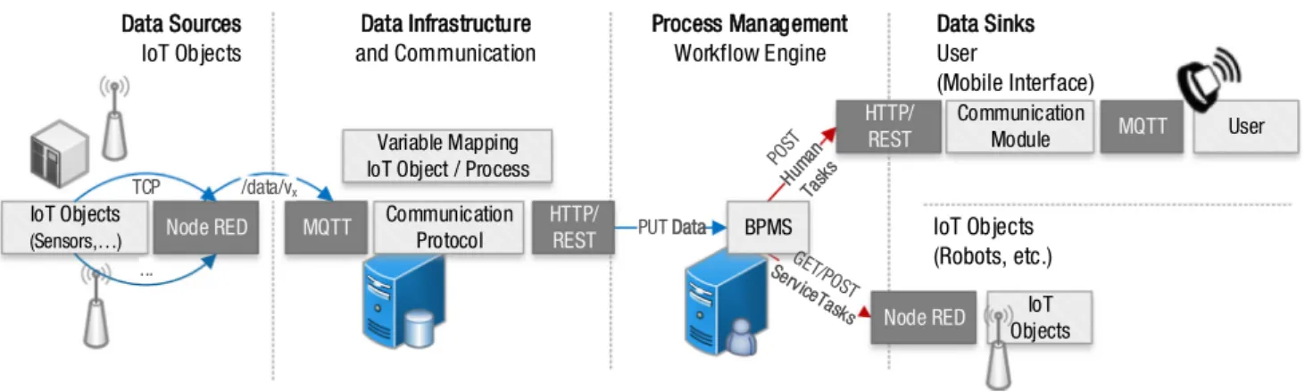
Fig. 3 Integrated communication architecture for IoT and BPMS
Input:C: Set of defined contextsC= c1, . . . ,c|C|
Input:U: Set of registered usersU=
u1, . . . ,u|U|
Input:VI: Set of intrinsic variablesVI=
vi1, . . . , vVI Input:VE: Set of extrinsic variablesVE=
ve1, . . . , vVE foreachc∈Cdo
r el V ar sc: set of relevant attributes-value pairs for contextc r el V ar sc← ∅
foreachvi∈VIdo
ifviamong related variables of cthen
valvi ←receive current value fromworkflow engine r el V ar sc←r el V ar sc∪ {(vi, valvi)}
foreachve∈VEdo
ifveamong related variables of cthen
valve←receive current value fromIoT middleware r el V ar sc←r el V ar sc∪ {(ve, valve)}
foreachu∈Udo
devi ceI d: identifier of mobile device dedicated tou ifuamong related users of cthen
send I n f or mati on(r el V ar sc,devi ceI d)
Algorithm 2:Provisioning context-specific IoT informa- tion
information for operators but not directly related to activities.
Thus, these values are visualized on additional tabs on the operators smartwatch.
5 Architecture and implementation
The described approach has been implemented based on a four layer architecture that is visualized in Fig.3. It con- sists of the following layers: (i) IoT objects like sensors as data sources; (ii) IoT infrastructure and communication mid- dleware; (iii) the BPMS; and (iv) data sink in form of IoT objects of human process participants. The layers are con- nected based on standard communication protocols.
5.1 IoT data acquisition and BPMS integration In order to connect arbitrary IoT objects, we make of the open-source platform Node-RED of IBM. The platform acts
as a communication middleware between various IoT pro- tocols and data sources like TCP sensors and the BPMS.
To allow the IoT objects at layer (i) to communicate with the IoT middleware at layer (ii) and the BPMS, respectively, a Message Queue Telemetry Transport (MQTT)4broker is used. MQTT is a queue-based publish/subscribe protocol, which is especially suited for applications where comput- ing power and bandwidth are constrained. The used MQTT topics are listed in Table3. IoT objects, i.e., sensors or actu- ators, represent publishers. They are connected to an IoT gateway using specific architectures such as Profibus, LAN, WLAN, or Bluetooth. A specific IoT variablevxis acquired and published on a MQTT topic/vx/data. Through a MQTT broker, the acquired data are sent to an acquisition applica- tion at layer (ii) that stores IoT data into a high-performance NoSQL database that follows the database scheme described in Sect.4.1. In our implementation, we used the latest version of the Apache Cassandra database.
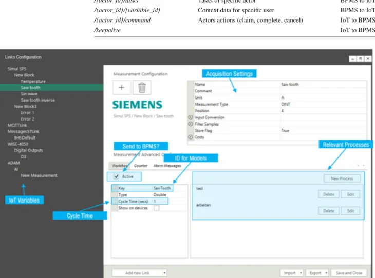
A distribution application at layer (ii) keeps the BPMS updated with the latest IoT values. All running instances of a particular process receive the corresponding data value. The application cyclically acquires the values from the database in a key-value structure and sends them to the BPMS. The configuration interface of the distribution application is given in Fig.4. On the left-hand side, the screenshot shows different connected IoT variables and their specific acquisition setting on the top of the window. The section at the bottom contains the configuration settings for the mapping to process vari- ables and the relevant process models. In our architecture, we used the latest version of the Camunda BPMS and there- fore communicated with the workflow engine by means of the Camunda Rest API,5i.e.,PUT, POST andGET HTTP requests as described in Fig.3. The tools at layer (ii) ensure that process relevant information stemming from the IoT is up to date. Through the acquisition tool, IoT data meta infor-
4 http://docs.oasis-open.org/mqtt/mqtt/v3.1.1/mqtt-v3.1.1.html.
5 https://docs.camunda.org/manual/7.8/reference/rest/.
Table 3 MQTT communication
between IoT objects and BPMS Topic Description Direction
/{variable_id}/data IoT sensor data IoT to BPMS
/{actor_id} Device configuration BPMS to IoT
/{actor_id}/tasks Tasks of specific actor BPMS to IoT
/{actor_id}/{variable_id} Context data for specific user BPMS to IoT /{actor_id}/command Actors actions (claim, complete, cancel) IoT to BPMS
/keepalive IoT to BPMS
Fig. 4 Configuration interface from IoT data variable to process model variable mapping
mation is provided that makes clear where the data stems from. Given the current IoT data values, the engine calcu- lates available activities.
5.2 User interface and IoT object interaction
As a mobile user interface, we implemented an Android- based smartwatch application that subscribes to specific MQTT topics. The distribution application cyclically requests the current user tasks from the Camunda API for each defined user and publishes to the correct MQTT topic, given the mobile device identifier, i.e., smartwatch device, configured on the BPMS (cf. Algorithm1). The application allows users to start and complete tasks as well as to initiate new process instances. The process of the device recognizing its configu-
ration is implemented as follows: the distribution application cyclically checks the user configuration in the BPMS. When a change is detected, it publishes the new configuration to the topic/{actor_id}. The assignment of a smartwatch to a spe- cific user is implemented by means of a unique device id, i.e., the smartwatch of a certain actor subscribes to the topic of its specific device identifier. Having established such connec- tions, the smartwatch communicates with the MQTT broker by subscribing to the following topics: The current tasks for a specific operator are published on the topic/{actor_id}/tasks.
The device sends operators commands, such as complete task to the topic /{actor_id}/command. The content of the message is forwarded straight to the BPMS using a POST request. Context-specific IoT data are sent to actors on topic /{actor_id}/{variable_id}based on Algorithm2. To prevent
the MQTT service at the watch to be killed, we implemented a keep alive communication (topic =/keepalive).
In case of active interactions with the IoT environment, BPMN Service Tasks are used. Here, we make use of the Camunda HTTP connector either to directly communicate with IoT objects that support HTTP communication or to send current variable values to Node-RED. An example sheds light on the complex architecture: Let us assume that after the completion of a certain human task a robot must be called to a specific position. This position is transferred as a parameter in a HTTP request send from the BPMS to the Node-RED platform. In Node-RED, the parameter is read from the body of the request and transformed to a message format according to a protocol that the corresponding robot can process. This way, the presented solution implements a full-fledged bidi- rectional communication between IoT objects like sensors, smartwatches or robots and a BPMS.
6 Evaluation and industrial applications
In this section, we describe the extensive evaluation of the proposed approach by means of several different application scenarios in industry. First, we present the application carried out in production industry. Second, we describe the use case of integrating human tasks and automated robot activities.
Finally, we describe the process-based implementation of the SEMI E10 specification for definition and measurement of equipment reliability, availability, and maintainability.6 Every use case can be characterized according to the follow- ing scheme: (i) type of acquired IoT data (cf. Sect.4.1.1and Sect.4.2); (ii) type of IoT data abstraction (cf. Sect.4.1.2);
and (iii) type of IoT data sinks (cf. Sect.4.2.2and Sect.4.3).
Our evaluation in different industry use cases has been car- ried out to show that our architecture works and can be applied in various use cases. Each use case provides a differ- ent implementation and view on the architecture. According to the Design Science approach, we created generalizable and transferable knowledge that can be applied in various application areas.
6.1 Application in production industry
The first use case has been implemented within a production industry scenario. More precisely, we introduced BPM sup- port for several production processes of production industry plants where paper is glued together to produce corrugated paper as raw material for cardboard boxes. Due to increasing automation and staff reduction, less operators are avail- able to control a corrugated paper production line. Hence, interactions between users and machinery requires several
6http://www.semi.org/en/.
location changes of users between control panels that result in delayed information flows. These delayed reaction times are frequently the reason for increased deficient products.
Furthermore, corrugation plants currently have to face a high fluctuation of employees such that process knowledge is lost over time. As a result, frequently new employees have to learn a basic understanding of production process control from scratch. Based on these issues, the general goals of the project carried out are (i) to increase operators productivity in terms of reducing stop times and increasing production speed, (ii) to facilitate the education and onboarding of new employees through transparent process knowledge and , (iii) to ensure traceability of work steps. The described solution has been rolled out in different plants. In total, forty produc- tion operators have been equipped with smartwatch devices and assigned a user in the BPM system. This first application case can be characterized as follows:
(i) Acquired IoT data: data from diverse PLCs (Siemens S7 communication protocol) and sensors according to the MQTT protocol
(ii) IoT data abstraction: cycle time mapping; acquisition of IoT data three times per second; distribution to BPMS every second
(iii) IoT data sinks: wearable smartwatch interface for oper- ators’ human tasks connected via MQTT protocol The overall BPMN process that is executed by a Camunda BPMS can be described as follows: After initializing internal helper variables, the control flow splits into different parallel paths where each path calls a specific subprocess depend- ing on certain IoT-based sensors conditions to be fulfilled.
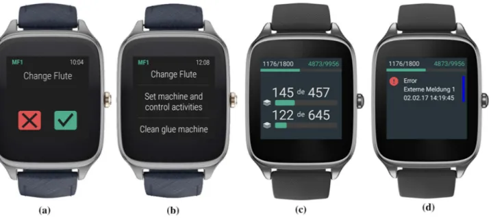
Each of these subprocesses reflects necessary operations that need to be performed to control production, e.g., the splice subprocess in Fig.1. The implemented process contains all IoT-enhanced modeling concepts that have been introduced in Sect.4.2. To directly notify operators when human actions are needed, plant personal has been equipped with smart- watches, i.e., mobile process cockpits as described before and as shown in Fig.5. Therefore, a user-group model has been defined in the BPMS. Here, available operators were assigned to a specific area of production that depicts their area of responsibility. Thus, depending on the area operators are working, the BPMS assigns a different set of tasks. Oper- ators are then pointed to new human tasks through visual, acoustic and, in case of noisy environments through haptic signals like vibration alarms. Furthermore, operators are used more effective because low priority work is aborted in order to perform high-priority work that could lead to machine stops.
In addition to currently available human tasks the IoT infrastructure provides diverse context-specific information on the smartwatch interface of operators. Depending on the
Fig. 5 Wearables:aunclaim/complete task;btasks;canddcontext info
specific group, a user is assigned to, the wearable device offers diverse context information to operators: at theDry- End(the area where produced corrugated paper leaves the plant), e.g., the remaining time of current production job, the remaining time to next stack transport, or the current pro- duction speed. Users at theWet-End(the area where original paper is inducted to the plant) receive continuously informa- tion w.r.t. the next necessary roll change or occurring error and defects of machinery modules. In addition, operators receive error messages and environmental information from the different plant modules. This way, concrete and goal- oriented information in error cases or warning messages for supply shortfalls can be transmitted to operators and enhance the over all process transparency and thus the quality of task execution (cf. Challenges in Sect.2.1). Through the described implementation, it was possible to significantly reduce reac- tion time intervals. The amount of deficient products was decreased and the overall quality of the produced corrugated paper has been improved. The overall equipment downtime was significantly decreased, since problems have been pro- hibited or recognized in advance and were solved proactively.
Hence, the overall equipment efficiency could be increased effectively. To quantify these findings, we analyzed process execution with the Camunda Statistics Plugin.7We tracked the corrugation process (i) for five days without operators using wearable devices and (ii) other five days with oper- ators being notified using smartwatches. In particular, we measured the average instance throughput time for a splice processes. The effectiveness of the approach has been mea- sured based on machine stop times and waste reduction. On average, 100 splices are executed per shift, i.e., 8 h of pro-
7https://github.com/camunda/camunda-cockpit-plugin-statistics.
duction. In case (i), we recorded a total stop time of 180 min, i.e., on average 12 min per shift. In case (ii), the stop time has been decreased to 60 min in total, i.e., 4 min per shift on average. The results show that the application of the IoT- enhanced BPMS leads to less machine stops because users need less time to recognize work to be done.
6.2 Application for robot human interaction
The second use case has been implemented with a robot that delivers certain drinks when the respective process is initiated by a human operator. The second application case can be characterized as follows:
(i) Acquired IoT data: robot job status variable via TCP protocol and Node-RED platform
(ii) IoT data abstraction: cycle time mapping; acquisition of IoT data every second; distribution to BPMS every second
(iii) IoT data sinks: wearable smartwatch interface for human tasks, robot (TCP protocol) where programs are initiated via Service Tasks (HTTP) and Node-RED pro- tocol transformation
The drinks are located in different boxes such that their position varies from drink to drink. We used Node-RED to establish the communication from a Universal Robots UR10 robot (accessible via TCP protocol) via HTTP to Camunda and vice versa. First, a human process participant starts a specific process by means of the smartwatch interface where she chooses a certain drink, e.g., cola, apple juice etc. Hav- ing started a new process instance a, Script Task is executed that sends the drink type as a parameter of a HTTP request
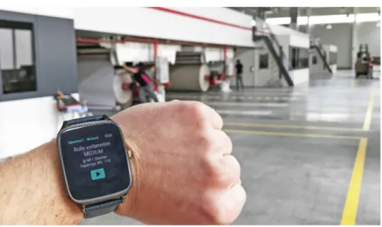
Fig. 6 Wearable process user interface in action
to the Node-RED platform. The parameter is transformed and embedded in a TCP conform message that is sent to the robot. Based on the given parameter, the robot initiates differ- ent programs that physically deliver the chosen drink (Fig.6).
Once the robot program has finished, it delivers a TCP mes- sage to Node-RED indicating the completion of the job. The IoT data acquisition module finally distributes the status of the job to the BPMS that, in turn, triggers a conditional inter- mediate event and executes a human task that completes the process. The use case successfully implements the full set of functionality of the integrated bidirectional communica- tion architecture. A screencast illustrating the application use case is available athttp://www.maxsyma.de/sosymmaterial/
usecase2.mov.
6.3 Specification of SEMI E10 equipment status via smartwatch
The third use case has been implemented to provide a wear- able user interface for the specification of equipment status according to the SEMI E10 standard. For demonstration pur- poses the process is initiated through a simple proximity sensor. The third application case can be characterized as follows:
(i) Acquired IoT data: proximity sensor signal via TCP protocol
(ii) IoT data abstraction: cycle time mapping; acquisition of IoT data every second; distribution to BPMS every second
(iii) IoT data sinks: wearable smartwatch interface for human tasks, interface to service infrastructure via
Service Tasks (HTTP) and Node-RED protocol trans- formation
This application was motivated by requests of a well- known German automation and production company that needed a wearable interface where operators can directly pro- vide information about equipment status in case of machine errors. The actual implemented processes vary from machine to machine; however, the common principle is outlined in Fig.7, where the signal of a simple proximity sensor is lost as a means to simulate a triggering event like machine errors.
In case such an event occurs, two human tasks are triggered and sent to human operators that need to solve and report the problem. Having completed both human tasks, the responsi- ble operator additionally needs to specify the type of error or machine status according to the SEMI E10 standard, respec- tively. The whole SEMI E10 status tree has been defined as a complex BPMN sub process that is sketched in Fig.8a. Here, the types and levels of status specifications are modeled as different paths through the process model. In case, the user chooses the statusDowntimeat the first level, and all other available options at this level are aborted through Bound- ary Events. At the next level, the operator can choose, a.o., betweenUnscheduled DowntimeandScheduled Downtime.
This selection procedure is continued until the final, i.e., most fine grained selection has been done. The multiple selection options are visualized as a list on the smartwatch interface as shown in Fig. 8 b). The whole SEMI E10 equipment sta- tus selection process model can be downloaded at http://
www.maxsyma.de/sosymmaterial/semi10.bpmn. A screen- cast illustrating the application use case is available athttp://
www.maxsyma.de/sosymmaterial/usecase3.mov.
Fig. 7 Specification of machinery issue via smartwatch
Fig. 8 Specification of SEMI E10 machinery status: (a) model in BPMN and (b) user interface
7 Conclusions, implications and future work
In this paper, we introduced an integrated approach for IoT- aware business process execution that tackled several open challenges in this area of applied research. As a funda- mental basis for the integration, we introduced an IoT data provenance framework. This technique allows us to con- sider current IoT data for interaction in arbitrary pre-defined process models that can be enacted by contemporary BPM execution systems. As demanded in many business cases, users need to be notified in real time when new tasks occur.
This has been implemented by means of wearable user inter- faces with configurable context-specific IoT data provision.
The presented approach combines the recording and anal- ysis of IoT and sensor data with technology of process management. We clearly pointed out that the presented inte- gration can be implemented based on existing concepts and technical solutions. The standard process modeling language BPMN offers adequate modeling elements for the definition
and reference of IoT objects and the corresponding real-time data. Existing BPMS like Camunda implements a suitable connector to an IoT protocol like HTTP enabling a bidirec- tional communication architecture between IoT and process management.
Furthermore, we implemented and evaluated our approach within innovative BPM related use cases, e.g., carried out in production industry. Within this project, we implemented a sensor-enabled wearable process management combin- ing collected sensor data, wearable interfaces and executed BPMN models. First evaluations show that the solution improves the certainty of how and when specific work steps should be carried out and reduces the delay between work steps through mobile and sensor-enabled real-time task pro- vision. Of course the presented solution can be generalized to other industry types as well. As a summary, we want to out- line the most important aspects that we learned throughout this extensive project and which factors were mainly con- tributing to the successful completion of the case.