AN OPTION TO GENERATE SEEDED FEL RADIATION FOR FLASH1 ∗
V. Grattoni † , R. W. Assmann, J. Bödewadt, C. Lechner,
M. M. Kazemi, I. Hartl, B. Manschwetus, DESY, 22607 Hamburg, Germany T. Plath, S. Khan, TU Dortmund University, 44227 Dortmund, Germany
W. Hillert, V. Miltchev, J. Rossbach, University of Hamburg, 22761 Hamburg, Germany
Abstract
The FLASH free-electron laser (FEL) at DESY is currently operated in self-amplified spontaneous emission (SASE) mode in both beamlines FLASH1 and FLASH2. Seeding offers unique properties for the FEL pulse, such as full co- herence, spectral and temporal stability. In this contribu- tion, possible ways to carry the seeded FEL radiation to the user hall are presented with analytical considerations and simulations. For this, components of the sFLASH seeding experiment are used.
INTRODUCTION
FLASH is the soft X-ray free-electron laser (FEL) user facility operated at DESY in Hamburg [1, 2]. The elec- tron bunches produced from the photo-injector of FLASH are accelerated and delivered to three different beamlines:
FLASH1, FLASH2 and the recently commissioned new beamline FLASH3 with the FLASHForward [3] experiment, dedicated to studies on beam-driven plasma wakefield ac- celeration. During user operation, FLASH1 and FLASH2 deliver self-amplified spontaneous emission (SASE) FEL radiation to the experimental halls. The unique properties of the FLASH photo-injector and the superconducting RF accelerating structures permit up to 800 bunches per RF pulse [4]. Nevertheless, the properties of the FEL pulses can be further improved with innovative seeding techniques.
The main advantages of a seeded FEL are the high spectral and power stability and the longitudinal coherence. These improved properties arise from starting up the FEL process from the microbunching developed from the interaction with a coherent seed pulse. Installed upstream of the main un- dulator of FLASH1, the sFLASH experiment is dedicated to studies of FEL seeding [5]. During dedicated sFLASH beamtime, only one electron bunch per RF pulse is gener- ated by the photo-injector, resulting in a repetition rate of 10 Hz. So far the sFLASH beamline has been operated in the high-gain harmonic generation scheme (HGHG) [6], which provides seeded FEL radiation at the 7
thand 8
thharmonics of the seed. Currently, echo-enabled harmonic generation (EEHG) is under study [5]. The photon pulses produced by the sFLASH experiment are extracted from the electron beamline in an extraction chicane placed in front of the FLASH1 main undulator. As the sFLASH beamline offers a seed laser system, it is interesting to theoretically study the
∗
Work supported by the Federal Ministry of Education and Research of Germany within FSP-302 under FKZ 05K13GU4, 05K13PE3, and 05K16PEA and the German Research Foundation within GrK 1355.
†
vanessa.grattoni@desy.de
possibility of producing HGHG-seeded FEL radiation and delivering it to the FLASH1 experimental hall.
SELECTED BEAMLINE ELEMENTS FOR SEEDING FLASH1
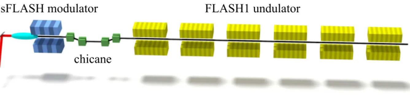
Figure 1 shows a schematic representation of the essential elements that are already present at FLASH and would be used for the HGHG operation. The scheme uses the second modulator of the sFLASH section, where the electron bunch is energy modulated by interacting with the seed laser pulse.
The extraction chicane after the sFLASH radiator converts the energy modulation into a density modulation and the main undulator of FLASH1 is used as radiator. The FLASH1 undulator has a fixed gap, so one has to tune very carefully the energy of the electron beam in order to satisfy the FEL resonance condition at the desired wavelength, as detailed in the following section.
ANALYTICAL CONSIDERATIONS Achievable Energy Modulation
The Ming Xie formalism [7, 8] has been used to estimate the maximum achievable power for the seeded FEL and its gain length.
The energy modulation amplitude of the electron beam re- sulting from the interaction with the seed laser pulse in the modulator is given by [9]
∆γ = r P
LP
02K
MOD· J J · L
MODγw
0, (1)
where P
Lis the laser pulse power, which is set to 100 MW in our calculations, w
0is the seed laser pulse waist, P
0= I
Am
ec
2/e ≈ 8.7 GW, where I
A= m
ec
3/e ≈ 17 kA is the Alfvén current, γ is the electron beam Lorentz factor, L
MODis the overall length of the modulator and K
MODis the undulator parameter (K) of the modulator, which has a maximum value of 10.8 and is adjusted in order to match the resonance condition λ
l= λ
MOD· (1 +K
MOD2/2)/(2γ
2), in our case λ
l= 266 nm. Furthermore, J J = J
0(K
2/(4 + 2K
2)) − J
1(K
2/(4 +2K
2)) is a correction of the coupling between the fundamental light wave and the electron bunch in the planar undulator (J
nis the Bessel function of the first kind of order n), and λ
MOD= 0.2 m is the period length of the modulator.
∆γ has been calculated for beam energies between 450 and 700 MeV. Even if Eq. 1 is an approximation, because the impact of both the transverse and the longitudinal intensity distribution of the seed laser pulse is not taken into account, the estimated energy modulation ∆γm
ec
2is comparable to
This is a pr eprint — the final v ersion is published with IOP
9th International Particle Accelerator Conference IPAC2018, Vancouver, BC, Canada JACoW Publishing
ISBN: 978-3-95450-184-7 doi: 10.18429/JACoW-IPAC2018-TUPMF079
TUPMF079 1448
Content from this w ork ma y be used under the ter ms of the CC BY 3.0 licence (© 2018). An y dis tribution of this w ork mus tmaintain attr ibution to the author(s), title of the w ork, publisher ,and DOI.
02 Photon Sources and Electron Accelerators
A06 Free Electron Lasers
FLASH1 undulator sFLASH modulator
chicane
Figure 1: Essential components required for the proposed operating scheme. The red line indicates the path of the seed laser pulses.
8 10 12 14 16 18 20
n 0
0.02 0.04 0.06 0.08
b
n55 60 65 70
R
56,OPT[ µ m]
b
nR
56,OPTFigure 2: The plot shows the maximum bunching factor b
nfor the different harmonics on the left axis and the R
56values on the right axis that gave these b
n.
the value measured during the normal sFLASH operation:
∆γm
ec
2' 404 keV [10].
Possible Achievable Harmonics
As the FLASH1 main undulator has a fixed gap, corre- sponding to an undulator strength of K
RAD= 1.23, there are only a few harmonics of the seed that are allowed. The resonance condition
λ
FEL= λ
RAD1 + K
RAD2/ 2
2γ
2(2)
allows operation ranging from the 9
thto the 20
thharmonic for electron beam energies between 450 and 700 MeV.
Estimation of the FEL Performance
With the modified Ming Xie formalism we can estimate the saturation power for the HGHG-seeded FEL [7]:
P(z) = P
th
1 3
z Lg 21 +
13z Lg
2+
1 2
exp h
z Lg
− √
3 i 1 +
2PPth∗F
exp h
z Lg
− √
3 i
, (3)
0.8 0.9 1 1.1 1.2 1.3 L g [m]
100 200 300 400 500 600
P FEL,sat [MW] n=14
n=9
n=20
I=300 A I=400 A I=500 A I=600 A
Figure 3: Saturation power and gain length for the harmonics in the accessible range and for several peak currents. Black curves indicate the saturation power for n = 9, 14 and 20.
where z is the coordinate along the radiator that has an overall length of L
RAD= 27 m and is normalized with L
g, which is the power gain length. P
th= ρ
FEL|b
n|
2P
beamis the power at the transition from the regime of quadratic increase (coherent harmonic generation) to the onset of the exponential growth of the FEL power, ρ
FELis the Pierce parameter, b
nis the bunching factor at the nth harmonic of the seed wavelength, P
beam= γmc
2I
peak/e is the power of the electron beam and P
∗F= P
F− P
th, where P
Fis the saturation power obtained from the correction given by Ming Xie [8].
The bunching factor for the different harmonics n [6] is b
n= exp
− 1 2 B
2n
2J
n(−nAB) , (4) where A = ∆γ/σ
γis the energy modulation ∆γ imprinted by the seed laser pulse on the electron beam normalized to the intrinsic energy spread of the electron bunch σ
γ. B = R
56k
lσ
γ/γ, where R
56is the longitudinal dispersion from the modulator to the radiator. For each harmonic, we have optimized the bunching factor by adjusting the R
56value. Figure 2 shows the achievable bunching factor for each harmonic number at which the FEL radiation is pro-
This is a pr eprint — the final v ersion is published with IOP
9th International Particle Accelerator Conference IPAC2018, Vancouver, BC, Canada JACoW Publishing
ISBN: 978-3-95450-184-7 doi: 10.18429/JACoW-IPAC2018-TUPMF079
02 Photon Sources and Electron Accelerators A06 Free Electron Lasers
TUPMF079 1449
Content from this w ork ma y be used under the ter ms of the CC BY 3.0 licence (© 2018). An y dis tribution of this w ork mus tmaintain attr ibution to the author(s), title of the w ork, publisher ,and DOI.
duced. The right vertical axis indicates the corresponding optimal values for R
56.
Figure 3 shows the calculated saturation power and the gain length at different currents (300 A, 400 A, 500 A, and 600 A) for the allowed harmonics. In all the cases, satura- tion is reached significantly before the end of the radiator.
In addition, the figure suggests that going for higher har- monics would be more advantageous because saturation is reached later in the radiator and the saturation power is higher. Operation at high peak currents makes it more diffi- cult to differentiate the seeded FEL power signal from the SASE signal. Table 1 shows an estimation of the contrast between the SASE and seeded signal for the different cur- rents for the simulations that are presented in the following section.
WORKING POINT SIMULATION
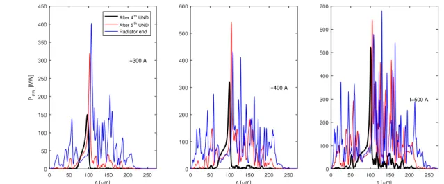
Simulations with the FEL code GENESIS1.3 [11] have been run to study the resulting photon pulses for different electron beam peak currents (300 A, 400 A and 500 A) at the 14
thharmonic. An emittance of 1mm·mrad and an intrinsic energy spread of σ
= σ
γmc
2= 60 keV has been assumed for the electron beam. In addition, the energy of the electron bunch has been set to E = 576 MeV to meet the resonance condition in the fixed-gap radiator. For the purpose of this simulation, the electron beam transport from the modulator to the radiator (including the chicane) was modeled by a transfer matrix.
Figure 4 shows the FEL pulses at different positions along the radiator for the different currents. We observe that the contrast between SASE radiation and seeded FEL radiation is not satisfactory at the end of the radiator, but it is still ac- ceptable after the fourth undulator. The FEL pulse energies at the end of the fourth undulator obtained in the simulation are compiled in the Table 1. The last column of the table
shows the contrast between the energy of the seeded FEL pulse and the SASE one. A set of simulation with seed laser pulse off has been performed to get the energy of the SASE FEL pulse (energy
SASE). As FLASH1 has quadrupoles in- stalled on movers after each undulator module, it is possible to stop the FEL amplification process by kicking the elec- tron bunch. In fact a quadrupole displaced transversely with respect to the beam direction acts as a dipole on the elec- tron beam. To kick the electron beam, preventing it to enter into the next undulator, the mover is set to the maximum displacement 0.95 mm.
Table 1: FEL pulse energies obtained from GENESIS simu- lations for the 14
thharmonic.
current energy peak power
energyenergyseededSASE
300 A 6.8 µJ 149.7 MW 20
400 A 12.3 µJ 320.3 MW 5
500 A 15.7 µJ 514.3 MW 2
CONCLUSION
In this contribution, theoretical studies of HGHG-seeded operation of FLASH1 using the already existing infrastruc- ture have been presented. Analytical calculations and simula- tions are in good agreement. The FEL process in the seeded fraction of the electron bunch is saturated after four (out of six) undulator modules. To preserve the energy contrast between seeded and SASE FEL pulses the FEL process can be stopped by kicking the electron beam using a quadrupole magnet. By doing so, a seeded FEL pulse with an energy of the order of 10 µJ is obtained.
0 50 100 150 200 250
s [µm]
0 50 100 150 200 250 300 350 400 450
PFEL [MW]
I=300 A After 4th UND After 5th UND Radiator end
0 50 100 150 200 250
s [µm]
0 100 200 300 400 500 600
I=400 A
0 50 100 150 200 250
s [µm]
0 100 200 300 400 500 600 700
I=500 A