DESIGN STEPS TOWARDS AN ELECTRON SOURCE FOR ULTRAFAST ELECTRON DIFFRACTION AT DELTA ∗
D. Krieg † , S. Khan, Center for Synchrotron Radiation, TU Dortmund University, Dortmund, Germany T. J. Albert, K. Sokolowski-Tinten, University Duisburg-Essen, Duisburg, Germany
Abstract
Ultrafast electron diffraction (UED) is a pump-probe tech- nique to explore the structural dynamics of matter, combin- ing sub-angstrom De-Broglie wavelength of electrons with femtosecond time resolution. UED experiments require ul- trashort laser pulses to pump a sample, electron bunches with small emittance and ultrashort length to analyze the state of the sample and excellent control of the delay between them.
Electrons accelerated to a few MeV in a photocathode gun offer significant advantages compared to keV electrons from electrostatic electron sources regarding emittance, bunch length and, due to the reduction of space charge effects, bunch charge. Furthermore, thicker samples and hence a wider range of possible materials are enabled by the longer mean free path of MeV electrons. In this paper, design steps towards a university-based UED facility with ultrashort and low-emittance MeV electron bunches are presented, includ- ing the transverse and longitudinal focusing schemes, which minimize space charge effects and nonlinearities.
INTRODUCTION
Ultrafast electron diffraction (UED) is a technique to ex- plore structural dynamics of matter using, for example, the pump-probe technique with an optical pump and an electron bunch as probe. The technique has to satisfy the relevant spatial ( < 1 Å) and temporal ( < 100 fs) resolution requir- ing a very high electron beam quality. The study of, e.g.
proteins, calls for a coherence length of about 30 nm. This translates into a bunch radius of 0.2 mm with a beam diver- gence of 12.5 µrad [1]. Moreover, short and reproducible bunch lengths down to some tens of fs are required. Recently, a design study for a university-based UED facility providing high-quality electron bunches was initiated in collaboration with the University Duisburg-Essen and the Center for Syn- chrotron Radiation of the TU Dortmund University which also operates the 1.5-GeV synchrotron light source DELTA.
In this paper, the main limiting factors will be explained and strategies will be presented to minimize them. In addition, aspects of the radiofrequency (rf) incoupling and the laser system will be discussed.
BASIC DESIGN
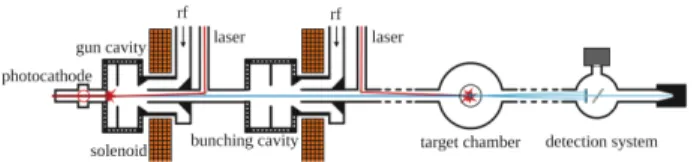
In Fig. 1, a conceptual design of a UED setup is shown.
A laser-excited photocathode is placed inside a 1.5-cell standing-wave cavity. A bunching cavity is used for lon- gitudinal compression. It is operated off-crest and imprints
∗ Work supported by MERCUR Pr-2017-0002
† daniel.krieg@tu-dortmund.de
Figure 1: Conceptual UED setup comprising a photocathode rf gun, a bunching cavity, a target chamber and a detector.
an energy chirp onto the electron distribution such that parti- cles at the tail of the bunch gain a higher velocity than those at the head. Solenoids compensate the transverse defocus- ing of both cavities. The electron source is followed by a target chamber, a detection system and the beam dump. The two main limitations for ultrashort high-brightness electron bunches are space charge effects and nonlinearities in the rf fields.
SPACE CHARGE EFFECTS
The Coulomb repulsion of the electrons enlarges the bunch in all dimensions in a nonlinear way. The transverse space charge field scales as E r ∝ r/R 2 where r is the ra- dial postion inside the bunch and R is the transverse bunch size. In longitudinal direction, it scales as E z ∝ z/L with z being the longitudinal position with respect to the bunch center and L being the bunch length. Typically, there are
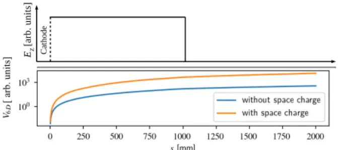
≈ 10 6 electrons in a bunch. A high-quality electron bunch should have a small 6D phase space volume but a small volume implies increased space charge effects. Minimizing the rf-induced emittance in the photocathode gun limits the laser pulse length in practice to approximately 10 ◦ of the rf phase [2]. Furthermore, space charge forces are massively suppressed with increasing electron energy. The transverse space charge force scales as F ⊥ ∝ 1 /γ and the longitudinal force as F ∥ ∝ 1 /γ 2 with the Lorentz factor γ [3]. Thus, the electrons have to be rapidly accelerated at the photo- cathode which requires a high acceleration of the order of 100 MV/m. The space charge effects are illustrated in Fig. 2.
Using ASTRA [4], the acceleration of an electron bunch was simulated with and without space charge. For simplicity, an electric DC field was considered to neglect effects like the rf curvature. For both cases, the 6D phase space volume was calculated.
NONLINEARITIES OF RF FIELDS
The curvature of the accelerating field [5]
E z (z,t) = E 0 sin (ωt + ϕ) cos (k z z), (1) translates into nonlinearities in the longitudinal phase space distribution of the electrons. Moreover, there is a nonlinear-
10th Int. Particle Accelerator Conf. IPAC2019, Melbourne, Australia JACoW Publishing
ISBN: 978-3-95450-208-0 doi:10.18429/JACoW-IPAC2019-TUPTS015
TUPTS015 1968
Content from this w ork ma y be used under the ter ms of the CC BY 3.0 licence (© 2019). An y dis tribution of this w ork mus tmaintain attr ibution to the author(s), title of the w ork, publisher ,and DOI
MC2: Photon Sources and Electron Accelerators
T02 Electron Sources
E
Z[a rb . u ni ts ]
Cathodes [mm]
[ ar b. u ni ts ]
Figure 2: Electric field and phase space volume V 6D as a function of the longitudinal position s .
ity of the longitudinal compression using a bunching cavity.
A longitudinal shift of the electrons in a drift space is given by the velocity difference within the bunch based on the energy chirp induced by the bunching cavity in a nonlinear way as shown in Fig. 3. The electron distribution in the longitudinal phase space is depicted at different locations.
The electron bunch length in the focus is increased in the presence of nonlinear energy chirp reducing the possible temporal resolution.
LONGITUDINAL AND TRANSVERSE FOCUSING
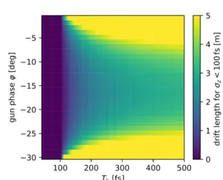
The focusing strategy should minimize both space charge effects and nonlinearities to reduce the effective 6D phase space volume and thus improve the electron beam quality. In the longitudinal case, a small electron density at the cathode, realized by a relatively long laser pulse, and compressing the electron bunches at higher energy with a bunching cavity will suppress space charge effects. The 6D phase space vol- ume, calculated using ASTRA simulations under variation of the laser pulse length T L , is shown in Fig. 4. In addition, the compression capability of the gun cavity alone is very limited. As shown in Fig. 5 the region of the gun phase leading to longitudinal compression of the electron bunch is typically around 30 ◦ . Furthermore, the energy spread caused by the gun cavity is relatively small. The shift of the relative longitudinal position ∆z in an electron bunch after a
Gun Drift 1 Drift 1 Buncher Drift 2 Focus
p
z[a rb . u ni ts ]
s [arb. units]
Figure 3: Schematic longitudinal phase space distributions of an electron bunch at different positions after the photo- cathode with a nonlinear energy chirp (bottom).
V6D[arb. units]