• Keine Ergebnisse gefunden

ContentfromthisworkmaybeusedunderthetermsoftheCCBY3.0licence( © 2018).Anydistributionofthisworkmustmaintainattributiontotheauthor(s),titleofthework,publisher,andDOI. THPMK0974530 02PhotonSourcesandElectronAcceleratorsT02ElectronSources doi: 9thInternation

N/A
N/A
Protected

Academic year: 2021

Aktie "ContentfromthisworkmaybeusedunderthetermsoftheCCBY3.0licence( © 2018).Anydistributionofthisworkmustmaintainattributiontotheauthor(s),titleofthework,publisher,andDOI. THPMK0974530 02PhotonSourcesandElectronAcceleratorsT02ElectronSources doi: 9thInternation"

Copied!
4
0
0

Wird geladen.... (Jetzt Volltext ansehen)

Volltext

(1)

FIRST CONCEPTUAL DESIGN STUDIES OF AN ELECTRON SOURCE FOR ULTRAFAST ELECTRON DIFFRACTION AT DELTA

D. Krieg , S. Khan, Center for Synchrotron Radiation, TU Dortmund University, Dortmund, Germany K. Sokolowski-Tinten, University Duisburg-Essen, Duisburg, Germany

Abstract

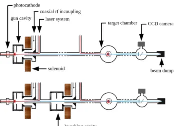
Ultrafast electron diffraction (UED) is a technique to study the structural dynamics of matter, combining diffraction of electrons with sub-angstrom De-Broglie wavelength with femtosecond time resolution. The method is complementary to X-ray scattering at free-electron lasers. UED pump-probe experiments require ultrashort laser pulses to pump a sample, electron bunches with small emittance and ultrashort length to analyze the state of the sample by diffraction, as well as excellent control of the delay between them. While most UED systems are based on electrostatic electron sources in the keV regime, electrons accelerated to a few MeV in a ra- diofrequency photocathode gun offer significant advantages regarding emittance and bunch length due to the reduction of space charge effects. Furthermore, the longer mean free path of MeV electrons allows for thicker samples and hence a broader range of possible materials. In this paper, a first conceptual design and simulation results for a university- based UED facility with ultrashort and low-emittance MeV electron bunches are presented.

INTRODUCTION

Ultrafast electron diffraction (UED) is a technique to ex- plore structural dynamics of matter e.g. as a pump-probe with an optical pump and an electron bunch as probe. The technique has to satisfy the relevant spatial (sub-1 Å) and temporal (sub-100 fs) resolution. The scattering cross sec- tion for electrons is 10 4 to 10 6 times higher than for X-rays so that a small number of electrons is sufficient to achieve results comparable to X-ray scattering [1]. However, a very high electron beam quality is required. The study of, e.g., proteins requires a coherence length of 30 nm, which trans- lates into a beam divergence of 12.5 µrad at a bunch radius of 0.2 mm [2]. Moreover, short and reproducible bunch lengths down to some tens of fs are required. In most cases, UED is performed using keV DC electron sources. They have been improved over years and produced scientific results. The usage of MeV electrons, i.e., by employing radiofrequency (rf) photoinjectors has several advantages [1].

1. The higher acceleration gradient allows to rapidly ac- celerate the electrons to relativistic energies. This sup- presses space charge effects, because both, the trans- verse and the longitudinal space charge force acting on a particle in the bunch, scale as 1/γ 2 with the Lorentz factor γ [3]. The generation of brighter electron beams with shorter bunch length is possible.

Work supported by MERCUR Pr-2017-0002

daniel.krieg@tu-dortmund.de

2. MeV electrons move nearly with the velocity of light so that there is no velocity mismatch with the optical pump pulse.

3. The elastic and inelastic mean free path lenghts are larger so that the use of thicker samples is possible.

Recently, a design study for a university-based UED facility providing high-quality electron bunches was initiated at the Center for Synchrotron Radiation of the TU Dortmund Uni- versity which also operates the 1.5-GeV synchrotron light source DELTA. In this paper, first simulation results are presented.

BASIC DESIGN

In Fig. 1, two options for a conceptual design of an UED setup are shown. In both cases, the electrons are emitted via a laser pulse hitting the photocathode, which is placed inside of a 1.5-cell standing-wave cavity. For a cavity with a radiofrequency of 3 GHz, for example, the accelerating gra- dient in the gun cavity is around 100 MV/m which rapidly accelerates the electrons to relativistic energies. The subse- quent solenoid compensates the transverse defocussing of the cavity [4,5]. The electron source is followed by the target chamber, a detection system and the beam dump. Using the photocathode laser also to excite the sample would provide a natural synchronization for pump-probe measurements. In the second option of Fig.1, a bunching cavity is used to pro- vide additional longitudinal focusing. It is operated off-crest and imprints an energy chirp onto the electron distribution

Figure 1: UED setup without (top) and with a bunching cavity (bottom) .

9th International Particle Accelerator Conference IPAC2018, Vancouver, BC, Canada JACoW Publishing

ISBN: 978-3-95450-184-7 doi: 10.18429/JACoW-IPAC2018-THPMK097

THPMK097 4530

Content from this w ork ma y be used under the ter ms of the CC BY 3.0 licence (© 2018). An y dis tribution of this w ork mus tmaintain attr ibution to the author(s), title of the w ork, publisher ,and DOI.

02 Photon Sources and Electron Accelerators

T02 Electron Sources

(2)

such that particles at the tail of the bunch gain a higher ve- locity than those at head. The use of a bunching cavity has two main advantages:

1. The additional radiofrequency (rf) amplitude and phase provide more flexibility in adjusting the longitudinal focus.

2. The bunching cavity allows to linearize the longitudinal phase space distribution without harmonic cavities [6].

The main disadvantage of the usage of a bunching cavity is that a second rf transmitter or a circulator is needed to avoid coupling between the cavities. In addition, the bunching cavity has to be synchronized to the laser and the gun cavity precisely.

MAIN LIMITATIONS

There are two main limitations for ultrashort high- brightness electron bunches: The Coulomb repulsion of the electrons enlarges the bunch in all dimensions in a nonlinear way. The transverse space charge field scales as E r ∝ r/R 2 with the radial position r inside the bunch and the bunch ra- dius R. In longitudinal direction, it scales as E z ∝ z/L with the longitudinal position z in the bunch and the bunch length L [3, 7]. Secondly, the curvature of the accelerating field is translated into nonlinearities in the longitudinal phase space.

The accelerating field [7]

E z (z, t) = E 0 sin(ωt + ϕ) cos(k z z), (1) depends on the time t at which an electron is emitted. More- over, there is a nonlinearity of the longitudinal compression process itself. A relative shift of the electrons in a drift space is given by the velocity difference within the bunch which is based on the energy chirp induced by the bunching cav- ity. The correlation between energy and velocity β is given by γ = 1/ p

1 − β 2 . As a consequence, for any imprinted energy chirp that does not yield a linear velocity spread, a curvature and higher-order distortions are generated in the longitudinal phase-space distribution of the electrons. [6, 8].

Table 1: Main Simulation Parameters

bunch charge 100 fC

accelerating gradient 100 MV/m

rms laser radius at cathode 10 µm

rms pulse length of laser 100 fs

initial kinetic energy 0.27 eV

work function of cathode material 3.5 eV

laser photon energy 4.66 eV

frequency gun cavity 3 GHz

# of cells gun cavity 1.5

distance from gun to focus 5 m

transverse bunch radius at focus 0.5 µm

number of macro particles 1000

Figure 2: Minimum rms bunch length σ z color-coded as function of the laser spot size r L at the cathode and the laser pulse length t L .

SIMULATION STUDIES

First simulation studies with ASTRA [9] including space charge effects were performed. The ultimate goal of the simulation studies is to find a UED design, satisfying tem- poral and spatial requirements. For this purpose, the design without bunching cavity is chosen because the observable space charge effects and nonlinearities of the phase space should be similar to those including a bunching cavity. At first, the influence of the starting emittance at the cathode on the rms length σ z of the electron bunch was investigated.

The parameters used for this simulation can be found in Table 1. The electron bunch was longitudinally focused at z f = 5.0 m. Figure 2 shows a color-coded representation of σ z at the position z f of the focus under variation of the laser spot radius r L at the cathode and the laser pulse length t L . With the solenoid parameters, both, the transverse di- vergence was minimized at z f and the bunch radius was adjusted to 0.5 mm at z f . With a smaller laser spot radius at the cathode or a shorter laser pulse length, the starting emit- tance is smaller and shorter bunch lengths σ z in the focus are possible. A bunch charge of Q = 100 fC was chosen because this is typically required for UED at MeV energies [1, 8].

Space Charge Effects

The smallest bunch length σ z at the longitudinal focus is a measure for the influence of the space charge effects. Figure 3 shows σ z under variation of the accelerating gradient E 0

and the bunch charge Q. The bunch length has a minimum

100 200 300

E

0

[MV/m]

0.00 0.05 σ

z

[mm]

0 500 1000 1500

Q [fC]

0.01 0.02 0.03 0.04

σ

z

[mm]

Figure 3: Left: Rms bunch length σ z in longitudinal focus with different amplitudes E 0 of accelerating gradients in the gun cavity. Right: σ z as function of bunch charge Q.

9th International Particle Accelerator Conference IPAC2018, Vancouver, BC, Canada JACoW Publishing

ISBN: 978-3-95450-184-7 doi: 10.18429/JACoW-IPAC2018-THPMK097

02 Photon Sources and Electron Accelerators T02 Electron Sources

THPMK097 4531

Content from this w ork ma y be used under the ter ms of the CC BY 3.0 licence (© 2018). An y dis tribution of this w ork mus tmaintain attr ibution to the author(s), title of the w ork, publisher ,and DOI.

(3)

0 500 1000 1500 2000 t

L

[fs]

0 10 20 30

% of lost particles

0 2 4 6 8

r

L

[µm]

0 50

% of lost particles

Figure 4: Percentage of lost particles as function of the laser pulse length t L and the laser spot radius r l .

between 100 MV/m and 150 MV/m. The maximum avail- able acceleration gradient for a gun cavity with a frequency of f = 3 GHz is E 0,max ≈ 110 MV/m. With increasing bunch charge Q, the bunch length increases as expected. A simulation with a gun cavity at a frequency of f = 1.3 GHz and an acceleration gradient of E 0 = 60 MV/m [10] shows a loss of particles caused by space charge effects. In Fig. 4, the percentage of lost particles due to space charge effects as a function of the laser spot radius at the cathode r L and the laser pulse length t L is shown. A lower electron density at the cathode, larger r L and/or t L causes a weaker Coulomb repulsion and hence less particles are lost.

Nonlinearities

To investigate the rf-induced nonlinearities in the longitu- dinal phase space, simulations with gun cavity frequencies of 1.3 GHz, 3.0 GHz and 6.0 GHz were performed with a laser pulse length of t L = 100 fs and a laser spot radius of r L = 10 µm. The choice of these values ensures that no par- ticles are lost in the f = 1.3 GHz setting (Fig. 4). Figure 5 shows the evolution of σ z along the electron path as well as the longitudinal phase-space distribution at the longitudinal focus z f . The smallest σ z is limited by the nonlinearities as wells as space charge effects. The nonlinearities increase with the frequency f , because for a given bunch length a wider range of the sinusodial curvature of the accelerating field is translated into the longitudinal phase-space distribu- tion.

CONCLUSION AND OUTLOOK

Space charge effects and nonlinearties are limiting fac- tors for a high-quality electron beam. To suppress the space charge effects, a high acceleration gradient or a low bunch charge is required. A small starting emittance is important to generate short bunches but on the other hand it boosts space charge effects because of the high electron density at the cathode. Rf-induced nonlinearities can be suppressed by using lower rf frequencies. Typically, the acceleration gradient is not high enough to suppress space charge effects efficiently for the required bunch charge. This can be seen by the particle losses in the case of the 1.3 GHz gun cavity.

Another way of reducing the nonlinearities is to use a har- monic cavity [11] or a stretcher mode, a linearization scheme without harmonic cavities [6]. In this scheme, the induced energy spread induced by the gun phase settings leads to a

Figure 5: Top: Electron bunch length at the longitudinal po- sition of the electron source for the three simulation settings.

Bottom: Longitudinal phase spaces at the longitudinal focus of the three simulation settings.

controlled expansion of the electron bunch in the drift space.

As a consequence, the curvature in phase-space and higher- order distortions change as well. The subsequent bunching cavity is used for linearizing and can be operated at the same frequency as the gun cavity. The field of the bunching cavity effectively acts like a higher-harmonic structure, because the associated field curvature is larger than the expanded bunch nonlinearities [6]. The simulation results also show that bunch lengths < 100 fs and the divergence ≈ 10 µrad re- quired for the spatial resolution < 1 Å are reachable. As for the rf frequency, 1.3 GHz will be not the best choice. The simulation shows that the possible acceleration gradients are not high enough to efficiently suppress the space charge effects. On the other hand, 6 GHz would lead to a strong influence of the nonlinearities. As a result of the present studies, the first choice for the rf frequency is f = 3 GHz.

It has to be studied whether a design with or without a bunching cavity provides the best beam quality. For this purpose, the solenoid optics has to be worked out as well as the laser and rf incoupling.

REFERENCES

[1] S. P. Weathersby et al., „Mega-electron-volt ultrafast electron diffraction at SLAC National Accelerator Laboratory“, Rev. of Sc. Instr., vol. 86, 073702, 2015.

[2] H. Delsim-Haeshemi, K. Floettmann, „Dark Current Studies at Relativistic Electron Gun for Atomic Exploration - REGAE“, in Proceedings of IPAC’2014, Dresden, Germany, 2014, paper MOPRI027, pp. 649-651.

[3] M. Ferrario et al., „Space Charge Effects“, CERN, Geneva, Switzerland, Rep. CERN-2014-009, p. 331-356.

[4] T. Rao, D. H. Dowell, „Beam Dynamics without Space Charge“, in An Engineering Guide To Photoinjectors, arxiv.org, 2013, p. 12.

[5] M. Hachmann et al., „Design and Characterization of Per- manent Magnetic Solenoids for REGAE“, in Proceedings of

9th International Particle Accelerator Conference IPAC2018, Vancouver, BC, Canada JACoW Publishing

ISBN: 978-3-95450-184-7 doi: 10.18429/JACoW-IPAC2018-THPMK097

THPMK097 4532

Content from this w ork ma y be used under the ter ms of the CC BY 3.0 licence (© 2018). An y dis tribution of this w ork mus tmaintain attr ibution to the author(s), title of the w ork, publisher ,and DOI.

02 Photon Sources and Electron Accelerators

T02 Electron Sources

(4)

IPAC’2015, Richmond, VA, USA, 2015, paper WEPMA030, pp. 2822-2825.

[6] B. Zeitler et al., „Linearization of the longitudinal phase space without higher harmonic field“, Phys. Rev. ST Accel. Beams, vol. 18, p. 120102, 2015.

[7] K-J. Kim, „RF and Space-Charge Effects in Laser-Driven RF Electron Guns“, Nucl. Instr. Meth., vol. 275, p. 201, 1989.

[8] K. Floettmann, „Generation of sub-fs electron beams at few- MeV energies“, Nucl. Instr. Meth., vol. 740, p. 34, 2014.

[9] K. Floettmann, „ASTRA - A space charge tracking algorithm“, http://www.desy.de/ mpyflo.

[10] V. Paramonov et al., „Design of an L-band normally conduct- ing RF gun cavity for high peak and average RF power“, Nucl.

Instr. Meth., vol. 854, p. 113, 2017.

[11] K. Floettmann et al., „Generation of ultrashort electron bunches by cancellation of nonlinear distortions in the longi- tudinal phase space“, TESLA-FEL, Hamburg, Germany, Rep.

2001-06, 2001.

9th International Particle Accelerator Conference IPAC2018, Vancouver, BC, Canada JACoW Publishing

ISBN: 978-3-95450-184-7 doi: 10.18429/JACoW-IPAC2018-THPMK097

02 Photon Sources and Electron Accelerators T02 Electron Sources

THPMK097 4533

Content from this w ork ma y be used under the ter ms of the CC BY 3.0 licence (© 2018). An y dis tribution of this w ork mus tmaintain attr ibution to the author(s), title of the w ork, publisher ,and DOI.

Abbildung

Figure 1: UED setup without (top) and with a bunching cavity (bottom) .
Figure 2: Minimum rms bunch length σ z color-coded as function of the laser spot size r L at the cathode and the laser pulse length t L .
Figure 4: Percentage of lost particles as function of the laser pulse length t L and the laser spot radius r l .

Referenzen

ÄHNLICHE DOKUMENTE

In an FEL seeding scheme known as “high-gain harmonic generation” (HGHG) [3], a magnetic chicane converts the energy modulation into a periodic density modulation (“mi-

In addition to the existing variable-gap undulator, the implementation of HGHG seeding requires a chicane, which guides the electron beam around the seed laser injection mirror,

placed in order to separate the short and long components of incoherent undulator radiation spatially (“femtoslicing” [2]) or a magnetic chicane may convert the energy modulation into

Figure 1: Top: Coherent harmonic generation (CHG) using a laser-induced electron energy modulation in an undulator (’modulator’), converted to a density modulation in a chicane

A limited contrast ratio as well as the fact that the hit rate of the external pulses with the electron bunches was dominated by the relative ar- rival time variations, which were

In 2011, digital bunch-by-bunch feedback units [1] and their corresponding kicker structures have been installed at the1.5-GeV electron storage ring DELTA (Fig. 1, Table 1) for

At DELTA, a 1.5-GeV electron storage ring operated as a light source by the Center for Synchrotron Radiation at the TU Dortmund University, coherent ultrashort THz pulses are

A light source facility employing the coherent harmonic generation (CHG) principle is being commissioned and op- erated since 2011 at DELTA, a 1.5-GeV electron storage ring at the