CONCEPT FOR A SEEDED FEL AT FLASH2
∗C. Lechner
†, R. W. Assmann, J. Bödewadt, M. Dohlus, N. Ekanayake
‡, G. Feng, I. Hartl, T. Laarmann, T. Lang, L. Winkelmann, I. Zagorodnov, DESY, 22607 Hamburg, Germany
S. Khan, DELTA, TU Dortmund University, 44227 Dortmund, Germany A. Azima, M. Drescher, Th. Maltezopoulos
§, T. Plath
¶,
J. Rossbach, W. Wurth, University of Hamburg, 22671 Hamburg, Germany
Abstract
The free-electron laser (FEL) FLASH is a user facility de- livering photon pulses down to 4 nm wavelength. Recently, the second FEL undulator beamline ’FLASH2’ was added to the facility. Operating in self-amplified spontaneous emis- sion (SASE) mode, the exponential amplification process is initiated by shot noise of the electron bunch resulting in photon pulses of limited temporal coherence. In seeded FELs, the FEL process is initiated by coherent seed radia- tion, improving the longitudinal coherence of the generated photon pulses. The conceptual design of a possible seeding option for the FLASH2 beamline envisages the installation of the hardware needed for high-gain harmonic generation (HGHG) seeding upstream of the already existing undulator system. In this contribution, we present the beamline design and numerical simulations of the seeded FEL.
INTRODUCTION
High-gain free-electron lasers (FELs) [1–4] generate ul- trashort photon pulses of unparalleled intensities, enabling the study of fundamental processes with unprecedented tem- poral and spatial resolution. In a self-amplified spontaneous emission (SASE) FEL, the exponential amplification process is initiated by the shot-noise of the electron bunch, result- ing in poor longitudinal coherence of the FEL radiation.
Seeding techniques using external light pulses can be ap- plied to transform the FEL into a fully coherent light source.
High-gain harmonic generation (HGHG) [5] uses an exter- nal, longitudinally coherent, light pulse that manipulates the electron beam in a short undulator (the modulator) generat- ing a sinusoidal energy modulation. The following chicane converts the energy modulation into a periodic pattern of microbunches. The harmonic content of this density modu- lation initiates longitudinally coherent FEL emission in the radiator at the desired harmonic. As the seeding process increases the energy spread of the electron beam, the achiev- able harmonic number is limited [6]. Single-stage HGHG seeding up to the 15th harmonic was demonstrated at the seeded FEL user facility FERMI [7].
∗Work supported by Federal Ministry of Education and Research of Ger- many under contract No. 05K13GU4, 05K13PE3, and 05K16PEA.
†christoph.lechner@desy.de
‡present address: Michigan State University, East Lansing, MI 48824, USA
§present address: European XFEL GmbH, 22869 Schenefeld, Germany
¶present address: DELTA, TU Dortmund University, 44227 Dortmund, Germany
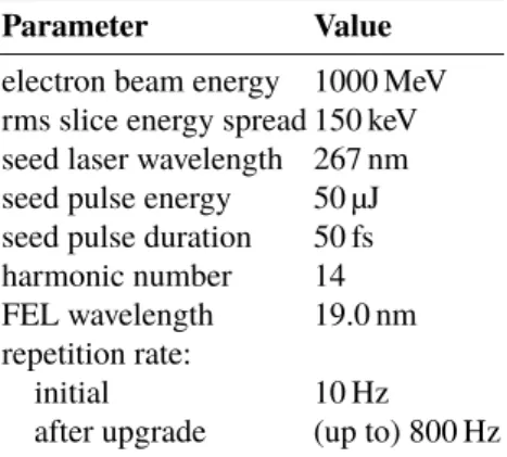
Table 1: Parameters for HGHG seeding at FLASH2 (for operation at the 14th harmonic)
Parameter Value
electron beam energy 1000 MeV rms slice energy spread 150 keV seed laser wavelength 267 nm seed pulse energy 50 µJ seed pulse duration 50 fs harmonic number 14 FEL wavelength 19.0 nm repetition rate:
initial 10 Hz
after upgrade (up to) 800 Hz
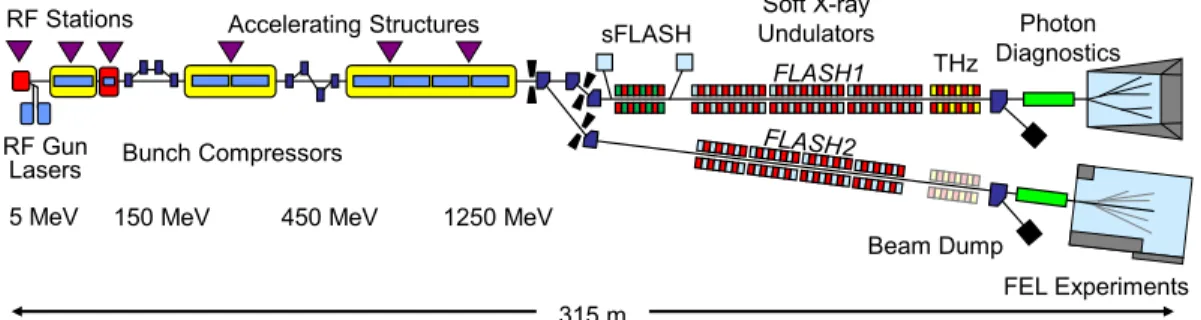
The FEL user facility FLASH [8] at DESY in Hamburg (see Fig. 1) has been in operation since 2005 [9], delivering high-brilliance SASE FEL radiation at wavelengths down to 4.2 nm. The superconducting linear accelerator is operated with 10 long radio-frequency pulses per second, during which trains with up to 800 high-brightness electron bunches (at a repetition rate of 1 MHz) can be accelerated to energies of up to 1.25 GeV. These bunch trains are distributed over two undulator beamlines using flat-top kickers. This enables operation at the 10-Hz bunch train repetition rate in both beamlines, the FLASH1 beamline with a fixed-gap undulator, where also the seeding experiment sFLASH [10] is installed, and the recently added FLASH2 beamline. Simultaneous SASE FEL delivery to photon user experiments at both FLASH1 and FLASH2 is now routinely achieved [11, 12] and simultaneous three-beamline SASE lasing (FLASH1, FLASH2, and sFLASH) was demonstrated [13] during machine studies.
Cascaded HGHG seeding was studied [14] in the con- ceptual planning phase of the FLASH2 undulator beam- line. However, this scheme was not implemented. In the present paper, the proposed implementation of single-stage HGHG seeding at FLASH2 up to a maximum harmonic number of 14, corresponding to a shortest wavelength of 19 nm, is described. Table 1 lists the key parameters for HGHG-seeded operation at 19 nm. The initial implementa- tion Phase 1A would provide seeding at a repetition rate of 10 Hz. Implementation Phase 1B is entered by upgrading the seed laser system to high-repetition-rate operation at a 100-kHz burst rate, matching the bunch pattern delivered by the superconducting linac. Thanks to this combination of superconducting linear accelerator and high-repetition-rate
38th International Free Electron Laser Conference FEL2017, Santa Fe, NM, USA JACoW Publishing
ISBN:978-3-95450-179-3 doi:10.18429/JACoW-FEL2017-MOP003
MOP003 34
ContentfromthisworkmaybeusedunderthetermsoftheCCBY3.0licence(©2018).Anydistributionofthisworkmustmaintainattributiontotheauthor(s),titleofthework,publisher,andDOI.
Seeded FELs
315 m
5 MeV 150 MeV 1250 MeV
Bunch Compressors 450 MeV Accelerating Structures RF Stations
Lasers RF Gun
Soft X-ray Undulators sFLASH
FEL Experiments Photon Diagnostics
Beam Dump FLASH1 THz
Figure 1: Layout of the FEL user facility FLASH. The superconducting linear accelerator is operated with long radio- frequency pulses and delivers trains of up to 800 electron bunches (at a repetition rate of 1 MHz). Flat-top kickers in the switchyard at the end of the linear accelerator distribute the bunches, enabling operation of both beamlines at the 10-Hz bunch train repetition rate.
Figure 2: Proposed layout of the FLASH2 undulator beamline for the implementation of HGHG seeding. The already existing variable-gap undulator system (comprising 12 2.5-m-long modules) is currently operated as a SASE FEL at wavelengths down to 4 nm. In front of this undulator, approximately 20 meter of beamline are currently partly used for electron beam diagnostics and the additional hardware would be installed there. In addition to the existing variable-gap undulator, the implementation of HGHG seeding requires a chicane, which guides the electron beam around the seed laser injection mirror, a variable-gap modulator, and a bunching chicane.
seed laser system, Phase 1B would be capable of producing up to 800 seeded FEL pulses per second. Finally, Phase 2 would be the implementation of echo-enabled harmonic gen- eration (EEHG) [15], a seeding method enabling seeding at shorter wavelengths. See [16] for an overview of potential FLASH2 seeding options and [17] for an earlier description of the FLASH2 seeding proposal.
PROPOSED IMPLEMENTATION OF HGHG SEEDING AT FLASH2
Presently, the already existing undulator of FLASH2, which comprises 12 2.5-m-long variable-gap modules, is operated as SASE FEL at wavelengths down to 4 nm [12].
A central constraint for any proposed FLASH2 modifica- tion is that it must not compromise SASE FEL performance, thus excluding modifications of the existing undulators. An approximately 20-m-long beamline section upstream of the undulators is partly used for electron beam diagnostics and, as illustrated in Fig. 2, the additional hardware needed for the implementation of HGHG seeding would be installed here. A dedicated seed laser system generates ultraviolet seed pulses with wavelength tunable between 260 nm and 320 nm, which is required to produce continuously tunable seeded FEL radiation. For 50-fs long seed pulses, the re- quired pulse energy at the laser system is 50 µJ (12 µJ at the modulator). The initial seed pulse repetition rate is 10 Hz.
HGHG seeding at a 100-kHz burst repetition rate would
become possible after a later upgrade of the seed laser sys- tem. The design and production of a laser system meeting these very demanding parameters requires a research and development effort.
The electron beam arriving from the FLASH linear ac- celerator is guided around the laser injection mirror by a 4-dipole chicane allowing to inject the ultraviolet seed ra- diation onto the orbit. These seed pulses interact with the electron bunches in the modulator (proposed parameters:
variable-gap undulator with a maximum magnetic field of 1.5 T at minimum gap, a period length of 75 mm, and 32 periods), generating a sinusoidal energy modulation. The bunching chicane, which is located between the modulator and the radiator, converts the energy modulation into peri- odic density modulations. The harmonics of this periodic current modulation initiate the FEL process in the seeded fraction of the electron bunch.
SIMULATIONS
For realistic simulations of the HGHG-seeded FEL, an electron distribution with an energy of 1.0 GeV was gener- ated in start-to-end simulations [18]. The machine parame- ters in this simulation allow for a peak current of 1.0 kA while delivering a normalized emittance and a slice en- ergy spread below 2 mm mrad and 150 keV, respectively.
For the tracking of the electron distribution from the radio- frequency photoinjector to the entrance of the FLASH2 un-
38th International Free Electron Laser Conference FEL2017, Santa Fe, NM, USA JACoW Publishing
ISBN:978-3-95450-179-3 doi:10.18429/JACoW-FEL2017-MOP003
Seeded FELs
MOP003 35
ContentfromthisworkmaybeusedunderthetermsoftheCCBY3.0licence(©2018).Anydistributionofthisworkmustmaintainattributiontotheauthor(s),titleofthework,publisher,andDOI.
Long. bunch coordinate [µm]
Power [W]
0 100 200 300
105 1010
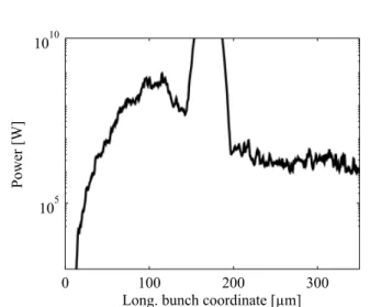
Figure 3: Temporal power profile of the photon pulse at the end of the radiator.
Wavelength [nm]
Spectral power [arb. units]
18.8 18.9 19 19.1 19.2
0 1 2 3 4× 10¹³
Figure 4: Spectrum at the end of the radiator.
dulator beamline, the simulation codes ASTRA [19] and CSRtrack [20] were used.
The baseline radiator operation mode is tapered operation of all 12 modules of the FLASH2 variable-gap undulator.
The studied profiles of the undulator parameterKfollow the tapering law [21]
K(z)=K0· a· (z−z0)2
1+b· (z−z0), (z≥z0)
withK0being the undulator parameter at the untapered en- trance of the undulator, andaandbare numerical parameters describing the tapering profile. The tapering sets in at longi- tudinal positionz0in the undulator, which should be a few gain lengths before saturation [21] of the seeded fraction of the electron bunch. At this position, the FEL gain process initiated by SASE is still in the exponential regime. The parametersaandbare determined by optimizing the con- trast between the seeded signal and the SASE background for given parameters (in particular energy modulation ampli- tude and generated bunching factor) using so-called “time-
independent simulations” with the code GENESIS 1.3 [22].
This simulation mode is an efficient way to study the FEL process in a single slice of the electron beam under the as- sumption of periodicity.
Next, the seeding performance of the optimized taper- ing profile, which was found in the optimization procedure described above, is investigated with time-dependent FEL simulations. The simulation is split into two GENESIS 1.3 runs: The first run simulates the laser-electron interaction in the modulator and stores the resulting phase-space distribu- tion to a file. In the second simulation run, this phase-space distribution is then further propagated through the bunching chicane and finally, the FEL process in the radiator is simu- lated. Figure 3 shows the temporal FEL pulse profile at the 14th harmonic (wavelength equals 19 nm) at the end of the FLASH2 undulator system and Fig. 4 shows the correspond- ing spectrum.
For the assumed parameters, the FEL process in the seeded fraction of the bunch saturates after 3 to 4 mod- ules of the undulator. At this position, the power constrast between the seeded signal and the SASE background is op- timal. In the following undulator modules, the seeded FEL power grows only marginally, while the FEL power in the unseeded parts of the bunch is still amplified exponentially.
Consequently, the contrast between seeding and SASE de- teriorates until the tapering profile begins to hamper SASE FEL amplification.
To improve the contrast, advanced operating schemes for the FLASH2 radiator, such as leaving the first undulator modules open, will be studied. For this scheme, the propaga- tion of the already bunched electron beam along the electron beamline under seeded longitudinal space-charge effects needs to be taken into account.
SUMMARY
In this contribution, we presented a proposal for the imple- mentation of single-stage HGHG seeding at FLASH2. The initial implementation would provide seeding at wavelengths down to 19 nm at a 10-Hz repetition rate. After an upgrade to a seed laser system supporting operation at a 100-kHz burst-mode pattern, up to 800 seeded FEL pulses per second would be generated.
ACKNOWLEDGEMENTS
We acknowledge discussions with colleagues from DESY accelerator division, DESY photon science, and University of Hamburg.
REFERENCES
[1] W. Ackermannet al., “Operation of a Free-Electron Laser from the Extreme Ultraviolet to the Water Window”,Nat.
Photonics 1, p. 336, 2007.
[2] P. Emmaet al., “First Lasing and Operation of an Ångstrom- Wavelength Free-Electron Laser”,Nat. Photonics 4, p. 641, 2010.
38th International Free Electron Laser Conference FEL2017, Santa Fe, NM, USA JACoW Publishing
ISBN:978-3-95450-179-3 doi:10.18429/JACoW-FEL2017-MOP003
MOP003 36
ContentfromthisworkmaybeusedunderthetermsoftheCCBY3.0licence(©2018).Anydistributionofthisworkmustmaintainattributiontotheauthor(s),titleofthework,publisher,andDOI.
Seeded FELs
[3] E. Allariaet al., “Highly Coherent and Stable Pulses from the FERMI Seeded Free-Electron Laser in the Extreme Ul- traviolet”,Nat. Photonics 6, p. 699, 2012.
[4] T. Ishikawaet al., “A Compact X-ray Free-Electron Laser Emitting in the sub-Ångström Region”,Nat. Photonics 6, p.
540, 2012.
[5] L. H. Yu, “Generation of Intense UV Radiation by Subhar- monically Seeded Single-Pass Free-Electron Lasers”,Phys.
Rev. A44, p. 5178, 1991.
[6] E. Hemsinget al., “Beam by Design: Laser Manipulation of Electrons in Modern Accelerators”,Rev. Mod. Phys.86, p.
897, 2014.
[7] M. Svandrliket al., “Development Perspectives at FERMI”, Proc. 8th Intl. Particle Accelerator Conf., Copenhagen, 2017, pp. 2666–2669.
[8] K. Honkavaara, “Status of the FLASH FEL User Facility at DESY”, presented at the 38th Intl. Free-Electron Laser Conf., Santa Fe, NM, USA, August 2017, paper MOD02, this conference.
[9] K. Honkavaaraet al., “FLASH: First Soft X-ray FEL Operat- ing Two Undulator Beamlines Simultaneously”,Proc. 36th Intl. Free-Electron Laser Conf., Basel, 2014, pp. 635–639.
[10] V. Grattoni et al., “Status of Seeding Development at sFLASH”, presented at the 38th Intl. Free-Electron Laser Conf., Santa Fe, NM, USA, August 2017, paper MOP042, this conference.
[11] B. Faatzet al., “Simultaneous Operation of Two Soft X-Ray Free-Electron Lasers Driven by One Linear Accelerator”, New J. Physics18, p. 062002, 2016.
[12] J. Rönsch-Schulenburg,et al., “Experience with Multi-Beam and Multi-Beamline FEL-Operation”,Proc. 8th Intl. Particle Accelerator Conf., Copenhagen, 2017, pp. 2621–2624.
[13] T. Plathet al., “Free-electron laser multiplex driven by a superconducting linear accelerator”,J. Synchrotron Radiation 23, p. 1070, 2016.
[14] A. Meseck, et al., “HGHG Scheme for FLASH II”,Proc.
33th Intl. Free-Electron Laser Conf., Shanghai, China, 2011, pp. 107–110.
[15] G. Stupakov “Using the Beam-Echo Effect for Generation of Short-Wavelength Radiation”,Phys. Rev. Lett102, p. 074801, 2009.
[16] K. Hacker “A Concept for Seeding 4-40 nm FEL Radiation at FLASH2”,Proc. 36th Intl. Free-Electron Laser Conf., Basel, Switzerland, 2014, pp. 286–296.
[17] C. Lechneret al., “Concept for a Seeded FEL at FLASH2”, Proc. 8th Intl. Particle Accelerator Conf., Copenhagen, Den- mark, 2017, pp. 2607–2610.
[18] G. Fenget al., “Seeded FEL Study For Cascaded HGHG Option For FLASH2”,Proc. 37th Intl. Free-Electron Laser Conf., Daejeon, Korea, 2015, pp. 246–250.
[19] K. Floettmann, “ASTRA”, DESY, Hamburg,http://www.
desy.de/~mpyflo/, 2011.
[20] M. Dohlus, T. Limberg, “CSRtrack: faster calculation of 3D CSR effects”,Proc. 26th Intl. Free-Electron Laser Conf., Trieste, Italy, 2004, pp. 18–21.
[21] E. A. Schneidmiller and M. V. Yurkov, “Optimization of a High Efficiency Free Electron Laser Amplifier”,Phys. Rev.
ST Accel. Beams18, p. 030705, 2015.
[22] S. Reiche, “GENESIS 1.3: a Fully 3D Time-Dependent FEL Simulation Code”,Nucl. Instrum. and Meth. A429, p. 243, 1999.
38th International Free Electron Laser Conference FEL2017, Santa Fe, NM, USA JACoW Publishing
ISBN:978-3-95450-179-3 doi:10.18429/JACoW-FEL2017-MOP003
Seeded FELs
MOP003 37
ContentfromthisworkmaybeusedunderthetermsoftheCCBY3.0licence(©2018).Anydistributionofthisworkmustmaintainattributiontotheauthor(s),titleofthework,publisher,andDOI.