• Keine Ergebnisse gefunden

The MAGIC-II gamma-ray stereoscopic telescope system

N/A
N/A
Protected

Academic year: 2021

Aktie "The MAGIC-II gamma-ray stereoscopic telescope system"

Copied!
3
0
0

Wird geladen.... (Jetzt Volltext ansehen)

Volltext

(1)

The MAGIC-II gamma-ray stereoscopic telescope system

D. Borla Tridon

,a

, T. Schweizer

a

, R. Mirzoyan

a

, M. Teshima

a

, for the MAGIC Collaboration

a

Max Planck Institute fuer Physik, Foehringer Ring 6, D-80805 Munich, Germany

Abstract

MAGIC-II is a stereoscopic system of imaging atmospheric Cherenkov telescopes (IACT) with the two largest dishes in the world. It is located in the Canary island of La Palma. The second 17m diameter telescope is currently under commissioning. MAGIC with its large reflector area, high quantum efficiency photomultipliers, optical signal transmission and fast digitization, will benefit from an improved shower reconstruction and increased background rejection thanks to the simultaneous observation by using two telescopes. Compared with the single MAGIC telescope, the new system will offer an improved angular and energy resolutions and 2 3 times higher sensitivity.

Key words: Cherenkov detectors, Photomultipliers, Hybrid Photo Detectors

1. Introduction

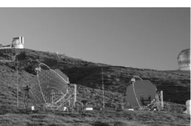
MAGIC-II is a system of two 17 m diameter mirror imaging atmospheric Cherenkov telescopes for very high energy gamma ray astronomy. The first telescope, MAGIC- I, is in operation since 2004. The second telescope was fin- ished in 2008 and is now under commissioning. We plan to operate it within a few months. The two telescopes can be operated independently or in stereoscopic mode. The two telescope system compared to a single one, is designed to provide an improved sensitivity in the stereoscopic opera- tion mode and lower the energy threshold. The latter will have a strong impact on pulsar studies and will extend the accessible red shift range, which is limited by the absorp- tion of high energy γ-rays by the extragalactic background light.

The structure of the second telescope is almost identi- cal with that of the MAGIC-I telescope. The lightweight reinforced carbon-fiber reflector frame, the drive system and the active mirror control (AMC) are only marginally improved with respect to the first telescope.

New developed components are introduced for improving the performance of the new telescope. Larger 1 m
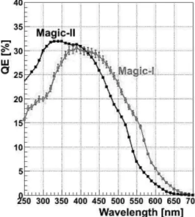
2

mir- rors elements have been developed as well as ultra fast sampling rates and low power consumption readout sys- tem. Increased quantum efficiency (QE) photomultipliers (PMTs) are used in the first phase and an upgrade to very high QE hybrid photo detectors (HPDs) is planned in the second phase. The entire signal chain from PMTs to the FADCs is designed to have a total bandwidth of 500 MHz.

The Cherenkov pulses from γ-ray are very short ( 2.5ns at the PMT). The parabolic shape of the reflector of the

Corresponding author. Tel.: +49-89-32354-312

Email address: dborla@mppmu.mpg.de (D. Borla Tridon)

Figure 1: The system of two telescopes. They are 85m far from each other following the results from montecarlo study showing moder- ate dependence of the sensitivity on the distance between the two telescopes.

telescope preserve the time structure of the light pulses.

A fast signal chain therefore allows one to minimize the integration time and thus to reduce the influence of the background from the light of the night sky (LONS).

2. The stereoscopic system

The two telescopes can be operated both in a single mode, by observing two different regions in the sky, and in a stereoscopic mode, with a simultaneous observation of the same region. The stereoscopic observation mode leads to a more precise reconstruction of the shower parameters as well as a stronger suppression of the background.

Images from the two telescopes are individually analyzed.

Hillas parameters are obtained from each image and then

Preprint submitted to TIPP09 Proceedings in NIMA April 18, 2009

(2)

combined to obtain stereo parameters. Source position is obtained from the intersection of the two major axis of the two images. In addition the height of the shower maximum can also be obtained. The stereo observation will improve the reconstruction of the axes of the air showers and their impact points. It will result in a better angular resolution, with an improvement of 20%, better energy estimation, with an energy resolution improving from 25% to 15% and higher cosmic-ray background rejection. The flux sensitiv- ity of the 2-telescope system is about 3 times better than that of a single telescope (MAGIC-I) at energies below 200 GeV.

Figure 2: Integral Sensitivity of the MAGIC-II is compared with MAGIC-I (300MHz FADC) and other experiments. The sensitivity is defined as integral flux of gamma events, exceeding the background fluctuation by factor 5, in 50 hours of observation.

3. The reflector

The 17m diameter parabolic reflector is tessellated with 247 square shape mirrors tile of spherical curvature, which are adjusted by the active mirror control (AMC) system of the telescope. Two different technologies are used for the production of the mirrors. The central part of the reflec- tor is composed of 143 mirrors made in aluminum using the diamond milling method (the same as MAGIC-I). The mirrors are made using a 2 mm thick plate of AlMgSi alloy, an aluminum honeycomb and an outer aluminum box all glued together. The front plates are then coated in order to protect them from weathering. The adjusted mirrors of the reflector show an excellent focal spot of 9mm size (one sigma value), while the reflectivity is 80%. In the two outer rings of the reflector there are 104 mirrors man- ufactured using a new technology: two 2mm thick glass plates are reinforced by using an Al honeycomb. The front plates are coated with a reflecting Al layer. The freshly made mirrors show a similar performance as the all-Al mirror with 85% of reflectivity.

4. The camera

The camera of the telescope is placed in the focus of the reflector at a distance of 17.5 m from the elevation axis of the telescope structure. MAGIC-II has an improved cam- era equipped uniformly with 1039 pixels of 0.1

o

diameter each, covering a trigger radius of 1.25

o

and a FoV of 3.5

o

. Every seven pixels are grouped in a hexagonal configura- tion to form one cluster. The clusters are inserted into holes between the two cooling plates. In these two plates the cooling liquid is running through pipes in order to sta- bilize the temperature of the camera. The modular design allows easier control and maintenance of the camera. On the front side the pixels are equipped with Winston cone type light guides to minimize the dead area between the PMTs. The pixels are based on the use of high quantum efficiency (QE) photomultiplier tubes (PMTs) from Hama- matsu (superbialkali type R10408, QE 32% at the peak).

We operate the 6 dynodes PMTs at a rather low gain of

Figure 3: QE of Magic-II PMT compared to the one of Magic-I

3 · 10

4

in order to perform observations also under moderate moonlight conditions. The PMTs signals are amplified by 700MHz bandwidth AC coupled preamplifiers. The PMTs are operated using a DC-DC converter (Cockroft-Walton high voltage generator), that converts DC electrical power from a low voltage level to a higher DC voltage level. The dynodes voltage distribution is such that the voltage be- tween the photocathode and the first dynode is 3 times the voltage between the following dynodes.

The electrical signal output of the PMT is converted us- ing the vertical-cavity surface-emitting laser (VCSEL) into light, which is then transmitted by optical fibers over 160 m to the readout system in the counting house. The camera electronics is powered by two 5 V power supplies mounted in two boxes placed in the bottom, outside the camera housing.

4.1. The slow control of the camera

The camera is controlled by a slow control cluster pro-

cessor (SCCP). A SCCP board installed in each cluster

controls the operations of the camera and reads several

2

(3)

Figure 4: Assembled PMT module to form a pixel in the upper figure and a full cluster of 7 pixels in the bottom figure

parameters. The HV of each pixel is set individually and the PMT current, the HV and the temperature at the VC- SEL are continuously monitored. A test-pulse generator board installed in each PMT to test the electrical chain is also controlled at this stage. In addition the slow con- trol operates the lids in front of the Plexiglas window that protects the PMTs and steers the power supplies of the camera. The SCCP has a flash programmable processor with 12 bits resolution DACs in a voltage range of 0 to 1.25 V and 12 bits resolution ADC in the range 0-2.5 V. Each SCCP board is connected to a VME board in one of the two VME crates in the upper and lower part of the cam- era. The VME crates are connected to the camera control PC in the counting house via an optical PCI to VME link.

5. The data acquisition system

The optical signals from the camera are transmitted via optical fibers to the counting house, where they are con- verted back to electrical signals. The latter are split in two branches. One branch is further amplified and transmitted to the digitizers, while the other branch goes to a discrimi- nator with an adjustable threshold. This generated digital signal is sent to the trigger system. The 2 GSample/s dig- itization and acquisition system is based upon a low power analog sampler called Domino Ring Sampler. The analog signals are stored in a multi capacitor bank that is orga- nized as a ring buffer. Each single capacitors in the bank are sequentially enables by a shift register driven by an internally generated 2 GHz clock locked by a phase locked loop (PLL) to a common synchronization signal. Once the trigger occurs, the signals in the ring buffer are read out at a lower frequency of 40 MHz and digitized with a 12 bits resolution ADC. The total bandwidth of the entire signal chain from the PMTs to the FADCs is for the time being limited by the use of relatively slow DOMINO-2 chips; the tipical output pulses have a 3.5ns width. It is foreseen to substitute soon the relatively slow chips by the next generation ones that have much improved parameters.

6. The camera upgrade with HPDs

An upgrade of the camera of the MAGIC telescopes is foreseen for the near future. A new photodetector type, Hybrid Photo Detector (HPD), will substitute part of the PMTs in the second camera. The HPDs consist of a vac- uum tube operated at 6-8 kV and an avalanche diode.

Thanks to the new camera design the HPD clusters can easily replace the PMT ones. The good single ph.e. reso- lution of HPDs and the low afterpulse rate are advantages of HPDs against PMTs, in particular double better single ph.e. resolution will result in about half the threshold.

Moreover the HPDs have higher QE than the PMTs and thus they will provide about 2 times more charge for the same imput light

Figure 5: Single photoelectron resolution for HPD with a gain of

78000

Acknowledgments

We would like to thank the technical and electronic staff of the IAC as well as of the MPI. The contribution from the German BMBF and MPG, the Italian INFN and INAF, the Spanish CICYT, the Swiss ETH and the Polish MNiI are vital for the MAGIC project.

References

[1] F. Goebel, et al., Status of the second phase of the MAGIC telescope , ICRC proceeding, 2007.

[2] C. Hsu, et al., The Camera of the MAGIC-II Telescope , ICRC proceeding, 2007.

[3] C. Hsu, et al., PMT Characterization for MAGIC-II Telescope , ICRC proceeding, 2007.

[4] D. Bastieri, et al., The reflecting surface of the MAGIC-II Tele- scope , ICRC proceeding, 2007.

[5] M. Doro, et al., The reflective surface of the MAGIC telescope, NIMA, 2008.

[6] T.Y. Sayto, et al., Recent Progress of GaAsP HPD development for the MAGIC telescope project, ICRC proceeding, 2007.

[7] E. Carmona et al., Monte Carlo Simulation for the MAGIC-II System, ICRC proceeding, 2007.

3

Abbildung

Figure 1: The system of two telescopes. They are 85m far from each other following the results from montecarlo study showing  moder-ate dependence of the sensitivity on the distance between the two telescopes.
Figure 3: QE of Magic-II PMT compared to the one of Magic-I
Figure 4: Assembled PMT module to form a pixel in the upper figure and a full cluster of 7 pixels in the bottom figure

Referenzen

ÄHNLICHE DOKUMENTE

Besides, because of the isotropy of the cosmic radiation, the images of hadronic showers have random orientations (cf. 3, right), whereas the cigar-shaped im- ages of gamma rays from

The chosen unidentified EGRET sources are compatible with the pulsar hypothesis. All of them should comply with the following criteria: 1) to be observable from La Palma, with lat

For each event the sky position is determined by using the so-called DISP-method [10, 16]. Figure 2a) shows the sky map of gamma-ray candidate excess events from the direction

Various possibilities for the production of very high energy (VHE) gamma rays near the GC are discussed in the literature, like accretion flow onto the central black hole,

Bartko et al., Search for Gamma Rays from the Galactic Center with the MAGIC telescope in proceedings of 29th International Cosmic Ray Conference (2005) [astro-ph/0508244].

Those energetic systems are believed to be as well γ-ray emitters, not only by interaction between the two stars [15][7] but also, several models of millisecond pulsars [4]

Then we assumed the energy spectrum with parameters (the power index, and the cut-off energy), and then multiplied the energy spectrum by the effective collection area and by

In the MAGIC telescope the measure of the absolute time is provided by a high-precision atomic clock (Rubclock), formed by a Rubidium standard frequency oscillator in conjunction with