A New Detector for Physics at HERA
I.Abt for the HERA-III Detector Group
MPI für Physik, Föhringer Ring 6, 80805 München, Germany
Abstract.
A new detector[1] designed to enlarge the kinematic range to study the structure functions F2 and Fl at the e[27.5GeV] p[920GeV] collider HERA at DESY is presented. The kinematic region of low x and low Q2is opened by extending the acceptance of the device to rapidities up to 8. The detector also allows studies of vector meson production and forward jet physics through a symmetric forward-backward spectrometer arrangement based on silicon tracking stations and silicon-tungsten calorimetry. GEANT studies detailing the projected capabilities are presented.
PHYSICS PROGRAM
The new detector will facilitate a huge variety of measurements in the field of e p[A] col- lisions. The highlights of the proposed program are:
• The measurement of F2from Q2=0:1 GeV2to Q2=10 GeV2with high precision to better understand the observed transition of the cross sections from partonic to hadronic behavior.
• The measurement of the longitudinal structure function, FL, particularly at Q2 values below 10 GeV2, where present theoretical and experimental uncertainties are very large.
• The measurement of diffractive and exclusive reactions (VM production and DVCS) over the full W range, and to values of jtj1:5 GeV2, with no proton dissociation background, to perform a three dimensional mapping of the proton and perform first extractions of generalized parton distributions.
• The measurement of forward jets and forward particle production up to pseudora- pidities of at leastη =6 to test in a direct way our understanding of parton branch- ing in strong interactions and to see the onset of collective phenomena. Acceptance for forward jets will also allow the measurement of F2to x=1 at moderate Q2. All of the above measurements should be performed with protons and with at least two nuclear targets (e.g., deuterons and Hg nuclei) in order to search for the gluon condensate and understand nuclear effects in parton distributions.
EXPERIMENTAL REQUIREMENTS
The luminosity requirements for the e p program are set by exclusive cross-section measurements at high t, F2measurements near x=1, and by the FL measurement. The need for data sets at three different proton energy settings (EP =460;690;920 GeV) with integrated luminosities of about 50 pb 1is anticipated. The luminosity required for the e A program has been estimated at 2 pb 1per nucleon. We do not anticipate needing electron beams - positron beams will suffice - since we are concerned primarily with the Q2region where photon exchange dominates.
The detector requirements resulting from the goals of the physics program are
• dipole magnets to separate scattered positrons from the beam
• precision forward and backward tracking up to rapidities of 8
• good electromagnetic calorimetry, matching the tracking acceptance
• forward [proton direction] hadron calorimetry
The dipole field facilitating the extension in rapidity range is oriented vertically.
In both the electron and proton hemispheres it extends from 0.3m to 4.8m from the interaction point and in the two hemispheres it has opposite polarity.
The interaction region can be designed using existing magnets. The first machine elements are positioned at5.8m.
DETECTOR CONCEPT
The main idea is to build a compact detector with tracking and central electromagnetic calorimetry inside a magnetic dipole field of 0.3T and calorimetric end-walls outside.
The detector inside the magnet[s] should not exceed a radius of 80 cm. The coordinate system has the z-axis parallel to the proton beam, the x-axis horizontal and the y-axis vertical. The positrons thus point towards negative z.
The tracking focuses on the forward and backward tracks. The calorimetry is to show the best performance in the central region where momentum measurements are intrinsically less precise due to the field configuration and thus e-π separation more difficult. Tracking forjηj<0:5 is currently not foreseen.
The precision tracking required translates into hit resolutions of less than approxi- mately 50 µm. This makes silicon strip detectors an obvious choice of technology. As the material budget will be important, double-sided detectors are desirable. A read-out- pitch between 50 µm and 100 µm will be adequate. Two double-sided detectors with appropriate stereo angle design can yield unambiguous space-points. For the baseline design we assume silicon tracking stations with two double-sided, 300 µ thick silicon strip detectors and support structures with material equivalent to 1.2 mm of carbon fiber.
This results in stations with a material budget equivalent to1 % of a radiation length X0.
The complete tracker is composed of planes oriented perpendicular to the beam. The planes are centered around the proton beam line and measure approximately 4040 cm2. They have a central cut-out that follows the beam-pipe design. Each plane is composed
Positron Hemisphere Positron Hemisphere
with 14 tracking planes up to 4.9 m
Proton Hemisphere
with 14 tracking planes up to 4.8 m Each plane is approximately
40 cm40 cm, consisting of
two double-sided silicon detectors plus support.
The design is almost symmetric around the interaction point.
FIGURE 1. Overview over the silicon tracker. The system is confined to cylinder with a radius of 30 cm.
Also visible is the widening beam-pipe.
of a top and a bottom half and two horizontal plugs that are adjusted to the required cut-out. In order to leave space for the end-wall calorimetry the silicon planes extend to 4.9 m in the electron and 4.8 m in the proton hemisphere. Figure 1 gives an overview of the design.
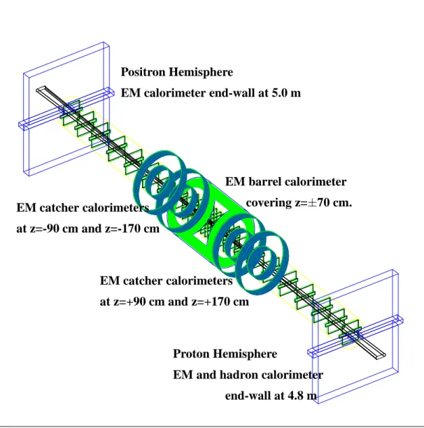
The electromagnetic calorimetry is required to match the forward tracking accep- tance and to cover the central region. The goal of a compact detector leads to silicon- tungsten as the choice of technology. The active components are confined to a tube with a radius of 60 cm. In order to cover 4π in an elongated design as this, multiple structures have to be adapted. Figure 2 gives an overview over the full detector, Fig. 3 depicts the central region.
Positron Hemisphere
EM calorimeter end-wall at 5.0 m
Proton Hemisphere
EM and hadron calorimeter end-wall at 4.8 m EM catcher calorimeters
at z=-90 cm and z=-170 cm
EM catcher calorimeters at z=+90 cm and z=+170 cm
EM barrel calorimeter covering z=70 cm.
FIGURE 2. Schematic overview over the detector components within6 m of the interaction point.
The silicon planes are visible in the center. The calorimeter system consists of a central barrel, 2 catcher rings on each side and 2 end-walls.
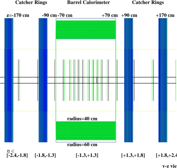
The central region in rapidity [jηj<1:3] is covered by a barrel structure with an inner radius of 40 cm. It extends to 70 cm in z. For a simple, non pointing layer geometry this results in a doubling of the path-length through a layer for a particle coming from the interaction point. The tungsten layers have a thickness of 1.75 mm which is equivalent to half a radiation length [X0] per layer. For particles hitting the end of the barrel the effective layer thickness is 1 X0. There are 50 layers resulting in an overall thickness of 25 X0at the center. The active medium are 500µm thick silicon pads. The pad size will be around 1cm1cm and there will be three longitudinal sections.
High rapidities, jηj > 2:4, are covered by end-walls. These end-walls cannot be
z=-170 cm -90 cm -70 cm +70 cm +90 cm +170 cm Barrel Calorimeter
radius=40 cm
radius=60 cm
Catcher Rings Catcher Rings
η2
[-2.4,-1.8] [-1.8,-1.3] [-1.3,+1.3] [+1.3,+1.8] [+1.8,+2.4]
y-z view
FIGURE 3. Overview over the central part of the em calorimeter system. The system is confined to a cylinder with a radius of 60 cm. Visible are the central barrel and the 4 catcher rings. The sandwich structures have active silicon planes and tungsten absorber plates.
large enough to cover all the non-barrel rapidity range, because of the certainly limited aperture of the magnets. Therefore the intermediate range in rapidity is covered by
“catcher rings”. Their absorber plates are perpendicular to the beam-line and cover radii from 30 cm to 60 cm. Two catchers are placed on each side of the interaction point. They start at z=90 cm and z=170 cm and cover the rapidity ranges from 1.3 to 1.8 and 1.8 to 2.4 with some reasonable additional overlap of about 10 % of a unit in rapidity.
Both catchers and the end-walls have tungsten absorber plates of 3.5 mm, i.e.1X0, thickness. They have 25 layers and again silicon pads of 500 µm thickness as active elements. In addition there is a need for hadronic calorimetry in the proton hemisphere.
0 0.1 0.2 0.3 0.4 0.5 0.6 0.7 0.8 0.9 1
W(GeV)
log10(Q
2)
-2 -1.5 -1 -0.5 0 0.5 1 1.5 2 2.5 3
0 100 200 300
FIGURE 4. Acceptance of the tracking system vs. W and Q2. A track has to pass 3 stations to count as accepted.
There are possibilities to use parts of existing calorimeters in this design. The re- quirements of the positron hemisphere end-wall could be met by the HERA-B tungsten shashlik calorimeter. The ZEUS uranium scintillator forward calorimeter with its elec- tromagnetic and hadronic sections could be used as the proton hemisphere end-wall.
DETECTOR PERFORMANCE
The detector performance was studied using a full GEANT3 simulation. The acceptance of the tracking system is depicted in Fig. 4. The excellent coverage of low Q2 events should be noted.
The momentum resolution was studied using different assumptions about the mate- rial in the detector, as shown in Table 1. These assumptions do not correspond to real technical designs; they are merely used to study the influence of material to guide later designs.
TABLE 1. Material budgets used to study the mo- mentum resolution. 600µm silicon represent 2 silicon wafers, 1.2 mm CF assume a uniform support structure of 1.2 mm carbon fiber and the beam-pipe is assume to have a thickness of 500µm aluminium.
Scenario silicon support beam-pipe standard 600µm 1.2 mm CF 500µm Al
light 600µm 1.2 mm CF none
extra-light 600µm none none
(pgen-prec)/pgen -0.5 -0.4 -0.3 -0.2 -0.1 -0 0.1 0.2 0.3 0.4 0.5 0
1000 2000 3000 4000 5000
ideal
Gaussian Sigma 0.68 percent Electron Momentum Resolution
(pgen-prec)/pgen -0.50 -0.4 -0.3 -0.2 -0.1 -0 0.1 0.2 0.3 0.4 0.5 1000
2000 3000 4000 5000 6000 7000 x102
extra-light
Gaussian Sigma 2.24 percent
(pgen-prec)/pgen -0.5 -0.4 -0.3 -0.2 -0.1 -0 0.1 0.2 0.3 0.4 0.5 0
1000 2000 3000 4000 5000 x102
light
Gaussian Sigma 2.59 percent
(pgen-prec)/pgen -0.50 -0.4 -0.3 -0.2 -0.1 -0 0.1 0.2 0.3 0.4 0.5 500
1000 1500 2000 2500 3000 3500 x102
standard
Gaussian Sigma 2.93 percent
FIGURE 5. Distribution of the normalized difference between generated and reconstructed momentum for an ideal detector, top left, the extra-light, top right, the light, bottom left, and the standard, bottom right, scenario [see also Table 1].
Single track events are used to determine the resolution. All impact points on the planes created in GEANT by a test particle are handed to a fit program. This program treats the components perpendicular and parallel to the magnetic field separately and then recombines the projections. It also smears the projected coordinates, simulated hits, by an assumed hit resolution. Two physics processes directly influence the resolution.
One is multiple scattering, the other one Bremsstrahlung. While multiple scattering changes the track in a random way, Bremsstrahlung always causes an energy loss and thus a bias. Some Bremsstrahlung photons convert and cause extra hits. In addition, some of the primary positrons interact and create a shower. All these effects make some pattern recognition, even for a preliminary study, indispensable. Normally a hit resolutionσhof 20µm is assumed. After a first fit using all simulated hits, the hit with the largest residual is taken out, if it has a residual larger than 3σh. This procedure is continued until either all hits have a residual of less than 3σh or there are only 3 hits left. A track is removed from the sample if the average residual is larger then 2 σh. This affects approximately 4 % of the tracks.
In Fig. 5 the overall distribution of the normalized difference between reconstructed and generated momentum is shown for the scenarios from Table 1 and for an ideal detector with no material. Obviously the material is important for the central part of the distribution which is dominated by multiple scattering. However, it is even more important for the tails caused by Bremsstrahlung. These tails contains up to 20 % of the tracks. The distributions are fit with a central Gaussian and an exponential tail. The central Gaussian part is taken as the resolutionδp/p.
The hit resolution is not critical below at least 50 µm when reasonable amounts of material for a silicon tracker are assumed. This is understandable, as hits in tracking stations with 1% X0 and a lever arm of about 50 cm, as is the situation for forward tracks in the current design, are subject to distortions of about 70 µm from multiple
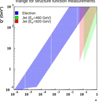
Range for structure function measurements
x Q2 (GeV2)
Electron Jet (EP=460 GeV) Jet (EP=920 GeV)
10-1 1 10 102 103
10-6 10-5 10-4 10-3 10-2 10-1 1
FIGURE 6. The kinematic coverage with the electron method assuming a 1 % electron momentum measurement at small-y (area shaded dark grey) and with a combination of the electron and jet information (area shaded medium grey: EP=920 GeV, area shaded light grey: EP=460 GeV). The intermediate region requires a measurement of y from the hadronic system.
scattering alone. However, hit resolutions become more important, if the the material can be reduced. A study of alternative silicon designs based on pixel detectors is underway.
The energy resolution for positrons hitting the barrel depends on the rapidity of the particle, i.e. on the impact location. Between the center and the end of the barrel the effective plate thickness doubles. The resolution is
14%
p
E2% and 15%
p
E2%
for the central and end part of the barrel respectively. The situation in the catcher rings and end-wall[s] is similar to that at the end of the barrel, as the plate-thickness was chosen to also correspond to 1X0there.
e-π Separation is straight-forward for particle energies above 5 GeV. Therefore the current studies focus on the most critical case of the lowest energy accepted, i.e. 2 GeV.
In areas where the momentum is measured it is possible to achieve rejection factors of larger than 50 with efficiencies above 95% by using the particle momentum and the longitudinal and transverse shower profile. In the central region where no momentum measurement is planned the rejection factor drops to around 25. This is still acceptable, as the total number of pion tracks in the positron hemisphere is generally less than 4.
FIGURE 7. A comparison between generated and accepted cross-section for events with a forward jet is shown in the top figure. The bottom figure depicts the acceptance for forward jets in the rapidityηand transverse momentum pT plane. The range covered by H1 and ZEUS is to the left of the vertical line.
0 0.1 0.2 0.3
0 0.1 0.2 0.3
0 0.1 0.2 0.3
0 0.1 0.2 0.3
10-4 10-2 1 10-4 10-2 10-4 10-2
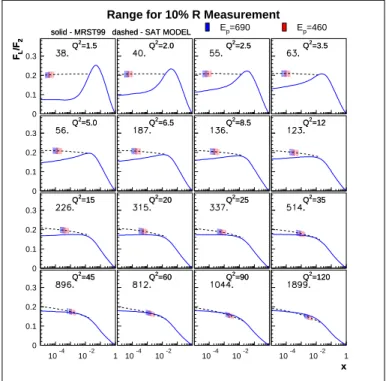
Range for 10% R Measurement
FL/F2
Q2=1.5
solid - MRST99 dashed - SAT MODEL
FL/F2
Q2=1.5
solid - MRST99 dashed - SAT MODEL Q2=2.0 Q2=2.0
Ep=690 Q2=2.5 Q2=2.5
Ep=460 Q2=3.5 Q2=3.5
Q2=5.0
Q2=5.0 QQ22=6.5=6.5 QQ22=8.5=8.5 QQ22=12=12
Q2=15
Q2=15 QQ22=20=20 QQ22=25=25 QQ22=35=35
Q2=45
Q2=45 QQ22=60=60 QQ22=90=90 Q2=120
x Q2=120
x 10-4 10-2 1
FIGURE 8. The x-range where a 10 % or better measurement of FL is possible is shown in different Q2bins. The area shaded in light grey is deduced from data with EP=920 and EP=460 GeV, while the area shaded in dark grey is determined by the combination of EP=920 and EP=690 GeV. The required luminosity is given in each bin in the upper left corner (in pb 1). Note that bins will be combined at high Q2to obtain statistically significant measurements. Plausible predictions are indicated by the solid and the dashed lines.
PHYSICS PERFORMANCE
The kinematic range targeted for F2is depicted in Fig. 6. It should be noted that though the main focus is to extend the accessible range to lower x, there are also opportunities at large x by using jet information. Figure 7 demonstrates the good acceptance for events with a forward jet. In addition Fig. 7 provides a comparison between the jet acceptance of the detector proposed here and the existing detectors ZEUS and H1.
Figure 8 demonstrates the power of this detector to distinguish between different predictions for FL in the low x, low Q2regime where theoretical prediction have a large variation.
CONCLUSIONS
A new detector especially focused on the low x, low Q2kinematic regime of e p physics at HERA would be able to make a major contribution towards the better understand- ing of the proton structure. A detector based on silicon tracking and silicon-tungsten- calorimetry within a dipole magnetic field can provide the required performance.
REFERENCES
1. H. Abramowicz et al, A New Detector foe HERA Letter of Intent submitted to DESY PRC, May 2003, MPI-PhE/2003-06
![FIGURE 5. Distribution of the normalized difference between generated and reconstructed momentum for an ideal detector, top left, the extra-light, top right, the light, bottom left, and the standard, bottom right, scenario [see also Table 1].](https://thumb-eu.123doks.com/thumbv2/1library_info/4002039.1540564/7.918.251.676.52.340/distribution-normalized-difference-generated-reconstructed-momentum-detector-standard.webp)