Inelastic light-scattering from spin-density excitations in the regime of the persistent spin helix in a GaAs-AlGaAs quantum well
C. Sch¨onhuber,1M. P. Walser,2G. Salis,2C. Reichl,3W. Wegscheider,3T. Korn,1and C. Sch¨uller1,*
1Institut f¨ur Experimentelle und Angewandte Physik, Universit¨at Regensburg, D-93040 Regensburg, Germany
2IBM Research-Zurich, 8803 R¨uschlikon, Switzerland
3Solid State Physics Laboratory, ETH Zurich, 8093 Zurich, Switzerland
(Received 20 December 2013; revised manuscript received 23 January 2014; published 6 February 2014) We have investigated the intrasubband spin-density excitation (SDE) in an asymmetrically doped GaAs- AlGaAs single quantum well with balanced Rashba and Dresselhaus spin-orbit interaction strengths by inelastic light scattering. For this unique symmetry, the combined spin-orbit field is either parallel or antiparallel to the [1¯10] in-plane direction of the quantum well for all wave vectors of the two-dimensional reciprocal space. In backscattering geometry, the SDE is formed by spin-flip intrasubband transitions of the spin-split subband. Via the splitting of the intrasubband SDE, we have directly detected the spin splitting of the conduction band due to the anisotropic spin-orbit field. As expected, the splitting is nonzero if a wave vector is transferred perpendicular to the direction of the spin-orbit field and close to zero for a parallel wave-vector transfer. The extracted values for the spin-orbit strength and for the wavelength of a persistent spin helix compare well with results of previous experiments of direct spatial mapping of the spin helix.
DOI:10.1103/PhysRevB.89.085406 PACS number(s): 73.20.Mf,73.21.Fg,73.61.Ey,78.30.−j I. INTRODUCTION
In low-dimensional semiconductors, made out of materials with zinc-blende structure, there are two important contri- butions to relativistic spin-orbit coupling of free electrons:
One arises due to the bulk inversion asymmetry (BIA) of the crystal lattice [1] (Dresselhaus effect). The second one can be important if there is a structure inversion asymmetry (SIA) present in the sample [2] due to, e.g., electric fields, caused by external gates and/or modulation doping (Rashba effect).
In a two-dimensional electron system (2DES), the spin-orbit coupling leads to a spin splitting of the free electrons, even at zero external magnetic field, which depends onk, the wave vector of the electron in the plane of the 2DES. Generally, this spin splitting is anisotropic within thekx-ky plane of a (001)-oriented 2DES. In pioneering works [3–6], Jusserand et al.and Richardset al.have shown that the anisotropy of the spin splitting of the electrons in the plane of the 2DES can be probed by inelastic light scattering (Raman scattering) on spin- flip single-particle transitions in highly doped GaAs-AlGaAs quantum wells. Ganichev et al. [7] reported that by angle- dependent investigations of spin photocurrents, employing the spin-galvanic effect, the anisotropic orientation of spins ink space can be probed directly. Recently, resonant inelastic light scattering (RILS) was also applied to probe the anisotropic spin splitting of two-dimensional holesystems inp-modulation- doped GaAs-AlGaAs quantum wells [8]. Not only is the spin splitting anisotropic for a 2DES in zinc-blende-type quantum wells, but also a giant spin-dephasing anisotropy was predicted for electrons within-planespin orientation [9]. Depending on the relative strengths of Rashba and Dresselhaus spin-orbit coupling constants,αandβ, spin dephasing should be strong in one in-plane direction and weak in the perpendicular direction.
The anisotropy should be maximal if both terms have equal strengths [10]. For this case, Schliemann et al. proposed a
*christian.schueller@ur.de.
spin transistor device which uses diffusive transport [11]. The predicted spin-dephasing anisotropy [9] was experimentally verified by polarization-resolved photoluminescence experi- ments [12] and by time-resolved Kerr rotation [13,14].
In the past few years there has been increasing interest in the very distinct case of equal Rashba and Dresselhaus coupling constants, α and β: It was proposed by Bernevig et al. [15] that for this case a new type of SU(2) spin rotation symmetry should be present, which should give rise to a persistent spin helix (PSH) for spins which are initially oriented out of the plane of a (001)-oriented 2DES.
Subsequently, experimental evidence of the PSH was reported by transient spin-grating spectroscopy [16], direct mapping via time- and spatially resolved Kerr microscopy [17], and weak localization/antilocalization experiments [18].
In this paper we report on RILS experiments on intrasub- band spin-density excitations (SDE) on a sample from the same wafer that was used in the experiments of Ref. [17], where evidence of the PSH was shown by direct spatial mapping. In contrast to the above-mentioned similar Raman experiments on one-side-doped quantum-well samples with large electron densities, where the in-plane anisotropy of the spin splitting is rather weak [3,4], in this sample with approximately equal strengths of Rashba and Dresselhaus spin-orbit couplings, the anisotropy is expected to be maximal:
In the [110] in-plane direction, where the existence of a persistent spin helix in the sample for out-of-plane spin excitation was already proven by direct mapping [17], the spin splitting for in-plane spins is expected to be maximal, and in the perpendicular [1¯10] direction, it should be much smaller, on the order of the difference between Rashba and Dresselhaus spin-orbit couplings (and the cubic Dresselhaus term). In the following we will show that evidence for the presence of the SU(2) spin rotation symmetry, which manifests itself by the above-described extreme case of spin-splitting anisotropy for in-plane spin orientations, can be proven by inelastic light scattering on the intrasubband SDE. After introducing details of the investigated sample and the setup
in Sec.II, we will show in Sec.IIItheoretically that only spin- flip transitions between the spin-orbit split-conduction-band subbands contribute significantly to the intrasubband SDE in quasi-backscattering geometry. This enabled us to derive directly from the experimental spectra of the SDE, which will be presented in Sec. IV, the spin splitting of the conduction band for the different in-plane directions and hence to verify the condition for the PSH in the investigated sample.
II. EXPERIMENTAL DETAILS
The sample is a two-side modulation-doped (001)-oriented GaAs-Al0.3Ga0.7As single quantum well with a 12-nm well width. The quantum well is placed 95 nm below the surface.
The asymmetric Siδdoping on both sides of the quantum well provides an approximately balanced Rashba and Dresselhaus spin-orbit interaction in the 2DES, i.e., α∼β. Figure 1(a) schematically shows the conduction-band profile of the sample in the area where the 2DES is located. The sheet carrier density and mobility of the 2DES are 5×10¹⁵m−2and 33 m2V−1s−1, respectively, as determined from transport experiments atT = 5 K under illumination. The RILS experiments were performed with a tunable continuous-wave Ti:sapphire laser, which was held at a fixed wavelength ofλ=789.9 nm in all experiments discussed in this paper, and the sample was mounted in a He flow cryostat at a nominal temperature ofT =5.5 K. The laser was focused to a spot with a diameter of about 100μm on the sample surface, and the power density in the laser spot was about 80 W/cm2. The scattered light was analyzed by a triple Raman spectrometer and detected by a liquid-nitrogen-cooled charge-coupled-device detector. The spectral resolution of the setup was about 34 μeV. The experiments were performed in quasi-backscattering geometry, as sketched in Fig. 1(b).
The use of an aperture in the beam of the scattered light allowed us to fix the scattering angleθ with an accuracy of about±4◦. By tilting the sample normal with respect to the directions of incident and backscattered light by an angleθ, a wave vector q can be transferred parallel to the plane of the 2DES [see Fig. 1(b)]. For backscattering geometry, the wave-vector transfer isq =(4π/λ)sinθif the small difference
kx║ [100]
ky║ [010]
[001]
Energy
(a) (c)
= aperture
2DES
laser lens (b)
spectro- meter
q
FIG. 1. (Color online) (a) (Color online) Schematic picture of the conduction-band potential profile of the 12-nm single quantum well. (b) Sketch of the experimental setup; an aperture is used to fix the direction of the backscattered light. (c) Constant-energy contours of an electron in the quantum well with balanced Rashba and Dresselhaus spin-orbit strengths. The spin eigenstates are either pointing in the [1¯10] direction (blue arrows) or in the [¯110] direction (red arrows).
in wavelengths between laser and inelastically scattered light is neglected, i.e.,λis chosen as the laser wavelength. All spectra were recorded for crossed linear polarizations of the laser and the scattered light (depolarized geometry).
III. THEORETICAL CONSIDERATIONS
The spin-orbit part of the Hamiltonian of an electron in a (001)-oriented quantum well is given by
Hso=α(kyσx−kxσy)+β(kxσx−kyσy) (1) when only terms linear ink are considered. Here, thex,y, andz directions are parallel to the [100], [010], and [001]
crystal directions, respectively. In the notation used here, both α and β are assumed to be positive quantities for a GaAs quantum well; that is, the electric field in the quantum well is pointing in the [001] direction [19] [see Fig. 1(a)]. An effectivek-dependent spin-orbit fieldhis usually defined via a Zeeman-type HamiltonianHso=σˆh, where ˆσ =(σx,σy,σz) is the vector of the Pauli spin matrices. With this definition, the spin-orbit field is given by
h=(αky+βkx)ex+(−αkx−βky)ey (2) in the above-used notation and linear inkapproximation. For the special situation discussed here, i.e.,α=β, the unique situation arises where the spin-orbit field reduces to
h=α(kx+ky)(ex−ey). (3) This means that the direction of the spin-orbit fieldhis, for all k=(kx,ky), either parallel or antiparallel to the [1¯10]
in-plane direction if the sum (kx+ky) in Eq. (3) is either positive or negative, respectively. Regarding the energy of an electron, this leads to the scenario, as sketched in Fig.1(c)for a constant energy, where the energy paraboloids for electrons with spins oriented in plane parallel or antiparallel toh are shifted by krelative to each other in the two-dimensionalk space. The magnitude of kis given by [15]
k= 4m∗α
2 . (4)
Here, m∗ is the effective mass of the electron. We have experimentally determined m∗ for our sample via inelastic light scattering on the cyclotron resonance excitation in a perpendicular magnetic field (not shown) under conditions similar to the experiments discussed in this paper. From these experiments we get m∗ =(0.075±0.001)me at the Fermi energy of the 2DES. This value is larger than the nominal band-edge value ofm∗=0.067medue to nonparabolicity of the conduction band [20] and the finite penetration of the electron wave function into the barrier material.
At the same time, kis the wave vector of the PSH for out-of-plane spin excitations, which is expected in the [110]
direction [15], and is connected to its wavelength λPSH via k=2π/λPSH. Figures 2(a) and 2(c) display cuts through the energy paraboloids in the [110] and [1¯10] directions, respectively. Spin up (blue arrows) and spin down (red arrows) in Figs. 2(a) and 2(b) mean that the spin is parallel to the [1¯10] and [¯110] in-plane directions, respectively. In the [110]
direction [dashed line in Fig.1(c)], the spin splitting ES,[110]
k EF
k [110]
Energy
EF q
k < q q
2 ES,[110]
[110]
(b)
EF
k [1-10] EF
q Eq
[1-10]
(d) (a)
(c) q << kF
ES,[110]
Energy EnergyEnergy
k
k
FIG. 2. (Color online) (a) Cut through the energy paraboloids in the [110] in-plane direction. (b) Schematic enlargement of the area around the Fermi energy. Spin-flip intrasubband transitions for the condition that k < qare indicated by curved arrows. (c) Cut through the energy paraboloids in the [1¯10] in-plane direction. (d) Same as (b) for the [1¯10] direction, where the spin splitting is zero.
[see Fig.2(a)] at the Fermi energy is connected to kvia ES,[110]= 2
m∗kF k, (5) wherekF is the Fermi wave vector of the 2DES.
Next, we consider the inelastic light-scattering process on the intrasubband SDE in more detail. In the light-scattering process, a virtual electron-hole pair is created by absorption of a laser photon. Either the electron or the hole is scattered by the creation of a SDE in the system (Stokes process). For the whole process, energy and momentum conservation holds; therefore, the energy of the scattered photon is decreased by the energy of the created excitation, and the wave-vector component parallel to the translationally invariant quantum-well planeqis transferred to the excitation, i.e., to the SDE. Macroscopically, an intrasubband SDE is a spin wave, which travels in the plane of the 2DES with wave vector q. The possibility to excite SDEs in inelastic light scattering is generally a consequence of spin-density fluctuations of the electron system and of spin-orbit interaction in the zinc-blende-type structure [21,22].
Microscopically, the SDE consists of spin-flip and non-spin- flip intrasubband single-particle transitions of individual elec- trons, which are coupled by exchange Coulomb interaction. In Figs.2(b)and2(d), spin-flip single-particle transitions, where an electron is excited from a state below the Fermi energy to an empty state above the Fermi energy and which may contribute to the intrasubband SDE, are indicated by curved arrows.
The single-particle transitions displayed here represent the high-energy cutoffs of the corresponding intraband spin-flip excitations for a given wave vectorq: Since the wave-vector dispersion of the electron is a two-dimensional paraboloid ink space, there is actually a continuum of possible single-particle transition energies for a given q, ranging from zero energy up to the high-energy cutoff [22]. The resulting sawtooth-like
spectral shape of the intrasubband single-particle excitation, which can be probed by inelastic light scattering, is described by a Lindhardt-Mermin line shape [23] with a nearly linear increase of the intensity, starting from zero at zero energy, and a very steep decrease at around the cutoff energy. Due to exchange Coulomb interaction, energy renormalizations of the spin excitation can occur. However, for the intrasubband SDE these collective effects are typically small [24] since the energies of the SDE are inside the continuum of intrasubband single-particle transitions and are hence Landau damped [22].
Therefore, most often, the collective intrasubband SDE is regarded as an intrasubband single-particle excitation. As already mentioned, spin-flip [see Figs.2(b)and2(d)] as well as non-spin-flip single-particle transitions contribute to the intrasubband SDE of the 2DES. However, in the following we will show that for the system of interest here, i.e., for a 2DES withα=β, only spin-flip transitions between states of opposite in-plane spin orientations, as displayed in Figs.2(b) and 2(d), should contribute to inelastic light scattering for crossed linear polarizations of incident and scattered light.
The scattering amplitudeAf i for inelastic light scattering by spin-density fluctuations, where an electron is excited from stateψinitialto stateψfinal, is given by [21,25]
Af i=γ(ei×e∗s)ψfinal|σˆ|ψinitial. (6) Here,ei(es) is the polarization vector of the incident (scattered) light wave, and γ is a factor which contains resonance enhancement effects [21]. Since all our experiments were performed with the same laser wavelength and the relevant Raman shifts are negligibly small,γ can be considered here to be a constant. If we choose the [001] direction (zdirection) as the quantization axis for the spin, the spin partψ±kof the electron wave function for spin orientationsinthe plane of the quantum well is given by [25]
ψ±k= 1
√2e−iφk/2[|↑ ±eiφk|↓], (7) whereφk is the angle between the direction of the spin-orbit fieldhand the [100] direction (x direction).|↑and|↓are the spin eigenvectors for spins parallel and antiparallel to the zdirection, respectively. If linear light polarizationseiandes
are considered, the scattering amplitudeAf ihas its maximum for perpendicular polarizations of incident and scattered light.
This is usually referred to asdepolarizedscattering geometry.
Then, for exact backscattering geometry (θ=0), the cross product in Eq. (6) has only a nonzerozcomponent. Because of the large difference in refractive indices of GaAs (∼3.6) and vacuum, this is a good approximation, even though in our experiments a finite tilt angleθis applied [see Fig.1(b)].
Therefore, we have to consider for the matrix element of the spin operator in Eq. (6) only thezcomponent. As described above, for the system considered here, withα=β, there are only two possible orientations of the spin-orbit fieldh, i.e., φk= −45◦or 135◦. Thus, the two possible spin eigenfunctions for in-plane spins are
ψ±k= eiπ/8
√2
|↑ ± 1
√2(1−i)|↓
. (8)
The plus (minus) sign corresponds to a spin oriented in the [1¯10] ([¯110]) direction. Inserting the wave functions from
Eq. (8) into Eq. (6), it is straightforward to verify that the scattering amplitude is given by A+−=A−+=γ for spin-flip excitations, i.e., if the spin directions of the initial and final states are opposite each other, andA++=A−−=0 for non-spin-flip excitations. From this it can be concluded that only spin-flip transitions between different spin subbands, as displayed in Figs. 2(b)and2(d), should contribute to the Raman signal. It should be noted that the deviation from exact backscattering geometry in our experiments also induces non-spin-flip transitions via theσx andσy components in the matrix element in Eq. (6). As already discussed, due to the large difference in refractive indices, this admixture is, however, expected to be small (see below).
IV. EXPERIMENTS AND RESULTS
We now come to the discussion of the experiments.
Figures3(a)and3(b)show series of depolarized spectra for different tilt anglesθ, fromθ=10◦(top spectra) toθ=38◦
0.0 0.5 1.0 1.5 2.0 2.5 3.0 3.5
(a) q || [110]
Intensity (arb. units)
Raman shift (meV) q || [1-10]
0.0 0.5 1.0 1.5 2.0 2.5 3.0 3.5
(b)
Intensity (arb. units)
FIG. 3. (a) Waterfall plot of depolarized inelastic light-scattering spectra of the intrasubband SDE for different wave-vector transfers q in the [110] in-plane direction. q increases from top to bottom spectra from 2.76×10⁶ m−1 to 9.79×10⁶ m−1. The spectra have been rigidly shifted successively by 75μeV to larger Raman shifts from bottom to top spectra. The bottom spectrum is not shifted.
(b) Same as (a) for wave-vector transfer q in the [1¯10] in-plane direction.
(bottom spectra). In the experiments in Fig.3(a), the wave vectorqwas transferred in the [110] in-plane direction, and in Fig.3(b)it was parallel to [1¯10]. The sharp cutoff at about 0.5 meV in the bottom spectra of both plots is due to the cutoff of the triple Raman spectrometer. The strong elastically scattered laser light is still visible around zero Raman shift. The spectra are horizontally shifted in the waterfall plot (see Fig.3 caption), so that the maxima in the spectra are approximately vertically aligned and marked by vertical dashed lines in Fig.3 for better comparison. The spectra of the intrasubband SDE in Fig.3(b)closely resemble the asymmetric Lindhard-Mermin line shape [23] of single-particle intrasubband excitations. For these excitations, the high-energy cutoffEq, which appears at around 1.6 meV in the bottom spectrum in Fig.3(b), is deter- mined by the Fermi wave vectorkF and the wave vectorqvia
Eq = 2
m∗kFq, (9)
assuming a parabolic band and qkF. Following the analysis in Ref. [23], we have determined the carrier density n=kF2/(2π) of the 2DES by analyzing Eq in the experimental spectra depending onq. From this analysis we get n=(4.40±0.75)×1015 m−2 for the electron density of the 2DES. This value is slightly smaller than the value, given above in Sec.II, obtained from transport measurements on a different piece of the sample. Furthermore, it is well known that in optical experiments with continuous-wave laser illumination the carrier density in the quantum well is typically reduced due to redistribution of the carriers between doped regions in the barriers and the quantum well.
The spectra in Fig.3(a), whereqwas transferred parallel to the [110] in-plane direction, exhibit two maxima, which are shifted against each other by about (0.37±0.05) meV, nearly independent of the transferred wave vectorq. These spectra resemble spectra on highly doped asymmetric GaAs quantum wells with relatively large spin splittings [3,4]. It can easily be verified theoretically that the high-energy cutoffs of the spin-flip transitions, as schematically displayed in Fig.2(b), are given by E±=Eq± ES,[110]. This may explain the experimental observation in Fig. 3: In the [1¯10] direction, where the spin splitting ES,[1¯10] is close to zero, only a single maximum is observed [Fig.3(b)]. In the [110] direction [Fig.3(a)], two maxima, which are equally shifted to both sides, are present. Of course, in principle, all possible states at around the Fermi energy with|k| ∼kFcan contribute to the observed excitation. Generally, the spin-flip transition energies E±(k) for a fixed direction ofqare given by [5]
E±(k)=Eqcos(δk−δq)± ES(k), (10) withEq being defined by Eq. (9). Here,δq is the fixed angle between q and the [100] axis, and δk is the corresponding angle between k and the [100] axis. Hence, E±(k) is maximal for δq =δk, which is the situation assumed above and in Eq. (9). Furthermore, Jusserandet al.[5] have shown that the peaks in the inelastic light-scattering spectra appear whendE±/dδk=0, i.e., around the high-energy cutoff when δq =δk. This justifies the simplification in our data analysis of considering only the energy diagrams forkq.
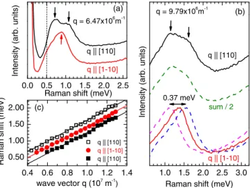
For a closer inspection, spectra, measured forq =6.47× 10⁶m−1 (θ=24◦), are compared in Fig.4(a). The different maxima in both spectra can clearly be recognized (marked
0.0 0.5 1.0 1.5 2.0 2.5
1.0 1.5 2.0 2.5 3.0 0.4 0.6 0.8 1.0 1.2 1.4
0.50 1.00 1.50 2.00 (c)
Intensity (arb. units)
(a) q = 6.47x10⁶m-1
(b) q = 9.79x10⁶m-1
q || [110]
q || [1-10]
Raman shift (meV)
q || [110]
Intensity (arb. units)
Raman shift (meV) 0.37 meV
q || [1-10]
sum / 2
q || [110]
q || [1-10]
q || [110]
Raman shift (meV)
wave vector q (107m-1)
FIG. 4. (Color online) (a) Comparison of depolarized spectra at fixed wave-vector transferq=6.47×10⁶m−1for two different in- plane directions. The vertical dashed line marks the cutoff of the triple spectrometer. (b) Same as (a), but for a wave-vector transferq= 9.79×10⁶m−1(red and black spectra). The blue and magenta dashed lines are reproductions of the red experimental spectrum, which are shifted by equal amounts to higher and to lower energies. The green dashed line is the sum of the red and magenta curves. (c) Positions of the maxima in the experimental spectra of the intrasubband SDE for different directions of wave-vector transferqvsq. The size of the symbols is representative of the experimental error.
by small arrows). At this relatively small value of q, the low-energy tails of the spectra are cut off by the spectrometer [vertical dashed line in Fig.4(a)]. Therefore, in Fig.4(b), we analyze the line shapes of the spectra for a larger wave-vector transfer of q=9.79×10⁶ m−1, where, however, the two maxima in the black spectrum are less well pronounced. The red and black spectra are the experimental spectra, recorded for wave-vector transfer in the [1¯10] and [110] directions, respectively. For the dashed blue and magenta spectra, we have shifted the experimental spectrum by equal amounts to higher and lower energies for a total shift of 0.37 meV, as indicated in Fig.4(b). The sum spectrum of the two shifted spectra [dashed green line in Fig.4(b)] represents an almost exact reproduction of the experimental spectrum, which was taken for a wave-vector transfer in the perpendicular in-plane direction [black spectrum in Fig.4(b)]. This provides strong evidence that the double-peak structure in the spectra in the [110] direction is a superposition of two intrasubband transitions with different cutoff energies, namely, the spin- flip transitions as sketched in Fig. 2(b). We note that both spin-flip transitions are expected to have the same strength since A+−=A−+=γ [see discussion of Eq. (6) above].
For the [1¯10] direction, where the spin splitting is close to zero, the two spin-flip transitions have the same energy Eq [see Fig. 2(d)], whereas for the [110] direction they are shifted by± ES,[110][Fig.2(b)]. Furthermore, this analysis underlines that the admixture of non-spin-flip transitions to the SDE due to the finite tilt angleθ in our experiments (see discussion in Sec.IIIabove) should be small, at least up to tilt angles ofθ38◦, which were applied here. Finally, Fig.4(c) shows the dependence of the peak positions in both scattering
configurations depending on the wave-vector transferq. The positions were extracted manually from the spectra. In Fig.4(c) data points which were derived from spectra for larger tilt anglesθ, i.e., largerq, as shown in Fig.3, are also included.
As expected from our simple theoretical analysis above, the peak separations are approximately independent of q; they are given by the spin splitting ES,[110]. We receive from our experimental data ES,[110]=(0.18±0.05) meV. From the facts that we observe a double-peak structure only in the [110]
direction and that the single peak, which is observed in [1¯10]
direction, is energetically in the middle of these two maxima, we conclude that in the investigated sample almost balanced Rashba and Dresselhaus spin-orbit strengths are realized. The limiting cases for the extracted values will be discussed below.
In the remaining paragraphs we will estimate some relevant quantities of our sample from our experimental results. The spin splitting ES,[110]in the [110] direction is given by [6,15]
ES,[110]=2(α+β)kF, (11)
whereas in the [1¯10] direction it is
ES,[1¯10]=2(α−β)kF. (12)
Using ES,[110]=(0.18±0.05) meV from our experiments andkF =(1.66±0.18)×108 m−1, as determined from the analysis ofEq(q) following Ref. [23], we obtain from Eq. (11) (α+β)/2=(2.77±0.83) meV ˚A. Provided thatα=β, this is the value for the Rashba and linear Dresselhaus coefficients α and β. This value is somewhat larger than the value determined in Ref. [17]. The small difference may be due to different illumination conditions of the sample and therefore a different electric field across the quantum well. Note that in Ref. [17], a transient in k due to a finite excitation spot size [26] has not been included in the analysis, yielding estimates for kthat are slightly too small.
From a careful inspection of our experimental spectra, we could estimate that we are not able to resolve peak splittings of the asymmetric line shapes in our experiments which are smaller than about 0.1 meV, i.e., spin splittings ES<0.05 meV. This means that, for the [1¯10] direction, we can determine, using Eq. (12), (α−β)<1.5 meV ˚A as an upper limit for the difference of linear Rashba and Dresselhaus coefficients. Using this upper limit, we get with Eqs. (11) and (12)α <3.5 meV ˚A andβ >2.0 meV ˚A as the limiting cases from our experiments.
From Eq. (5), we can estimate the wave vector k of the PSH, which gives k=(1.14±0.33)×106 m−1. With this result, the wavelength of the PSH can be computed to beλPSH=(5.5±1.5) μm. This compares fairly well to the wavelength, which is evident from direct mapping of the PSH in Ref. [17] for long time delays between pump and probe pulses. Finally, we want to note that the spin orientations of the spin-flip excitations, which we have investigated in this paper, are orthogonal to the spins of the PSH, which are parallel to the (1¯10) plane.
V. CONCLUSION
In conclusion, we have directly determined the spin splitting of a 2DES in an asymmetric GaAs-AlGaAs quantum well
with approximately equal strengths of Rashba and Dressel- haus spin-orbit coupling via inelastic light scattering on the intrasubband spin-density excitation. In the [110] in-plane direction, where the PSH for out-of-plane spin excitation was previously proven by direct spatial mapping, we find a spin splitting of in-plane spins of about 0.18 meV. In the perpendicular in-plane direction, the spin splitting is
found to be smaller than 0.05 meV within our experimental accuracy.
ACKNOWLEDGMENTS
We acknowledge financial support by the DFG via projects SPP 1285 and SFB 689 and by the SNF via NCCR QSIT.
[1] G. Dresselhaus,Phys. Rev.100,580(1955).
[2] Y. A. Bychkov and E. I. Rashba, Pis’ma Zh. Eksp. Teor. Fiz.39, 66 (1984) [JETP Lett.39, 78 (1984)].
[3] B. Jusserand, D. Richards, H. Peric, and B. Etienne,Phys. Rev.
Lett.69,848(1992).
[4] D. Richards, B. Jusserand, H. Peric, and B. Etienne,Phys. Rev.
B47,16028(1993).
[5] B. Jusserand, D. Richards, G. Allan, C. Priester, and B. Etienne, Phys. Rev. B51,4707(1995).
[6] D. Richards, B. Jusserand, G. Allan, C. Priester, and B. Etienne, Solid State Electron.40,127(1996).
[7] S. D. Ganichev, V. V. Belkov, L. E. Golub, E. L. Ivchenko, P. Schneider, S. Giglberger, J. Eroms, J. De Boeck, G. Borghs, W. Wegscheider, D. Weiss, and W. Prettl,Phys. Rev. Lett.92, 256601(2004).
[8] M. Hirmer, M. Hirmer, D. Schuh, W. Wegscheider, T. Korn, R.
Winkler, and C. Sch¨uller,Phys. Rev. Lett.107,216805(2011).
[9] N. S. Averkiev and L. E. Golub,Phys. Rev. B60,15582(1999).
[10] J. Kainz, U. R¨ossler, and R. Winkler,Phys. Rev. B68,075322 (2003).
[11] J. Schliemann, J. C. Egues, and D. Loss,Phys. Rev. Lett.90, 146801(2003).
[12] N. S. Averkiev, L. E. Golub, A. S. Gurevich, V. P. Evtikhiev, V. P.
Kochereshko, A. V. Platonov, A. S. Shkolnik, and Yu. P. Efimov, Phys. Rev. B74,033305(2006).
[13] B. Liu, H. Zhao, J. Wang, L. Liu, W. Wang, D. Chen, and H. Zhu,Appl. Phys. Lett.90,112111(2007).
[14] D. Stich, J. H. Jiang, T. Korn, R. Schulz, D. Schuh, W. Wegscheider, M. W. Wu, and C. Sch¨uller, Phys. Rev. B 76,073309(2007).
[15] B. A. Bernevig, J. Orenstein, and S.-C. Zhang,Phys. Rev. Lett.
97,236601(2006).
[16] J. D. Koralek, C. P. Weber, J. Orenstein, B. A. Bernevig, S.-C.
Zhang, S. Mack, and D. D. Awshalom,Nature (London)458, 610(2009).
[17] M. P. Walser, C. Reichl, W. Wegscheider, and G. Salis,Nat.
Phys.8,757(2012).
[18] M. Kohda, V. Lechner, Y. Kunihashi, T. Dollinger, P. Olbrich, C. Sch¨onhuber, I. Caspers, V. V. Bel’kov, L. E. Golub, D. Weiss, K. Richter, J. Nitta, and S. D. Ganichev,Phys. Rev. B86,081306 (2012).
[19] M. Studer, G. Salis, K. Ensslin, D. C. Driscoll, and A. C. Gossard, Phys. Rev. Lett. 103, 027201 (2009).
[20] L. Wissinger, U. R¨ossler, R. Winkler, B. Jusserand, and D. Richards,Phys. Rev. B58,15375(1998).
[21] D. C. Hamilton and A. L. McWhorter, in Light Scattering Spectra of Solids, edited by G. B. Wright (Springer, New York, 1969), p. 309.
[22] A. Pinczuk and G. Abstreiter, inLight Scattering in Solids V, edited by M. Cardona and G. G¨untherodt (Springer, Heidelberg, 1988), p. 153.
[23] G. Fasol, N. Mestres, A. Fischer, and K. Ploog,Phys. Scr.T19A, 109(1987).
[24] M. Berz, J. F. Walker, P. von Allmen, E. F. Steigmeier, and F. K.
Reinhart,Phys. Rev. B42,11957(1990).
[25] A. G. Mal’shukov, K. A. Chao, and M. Willander,Phys. Rev. B 55,R1918(1997).
[26] G. Salis, M. P. Walser, P. Altmann, C. Reichl, and W. Wegschei- der,Phys. Rev. B89,045304(2014).
![FIG. 2. (Color online) (a) Cut through the energy paraboloids in the [110] in-plane direction](https://thumb-eu.123doks.com/thumbv2/1library_info/5620844.1692148/3.911.81.433.102.393/fig-color-online-cut-energy-paraboloids-plane-direction.webp)
![FIG. 3. (a) Waterfall plot of depolarized inelastic light-scattering spectra of the intrasubband SDE for different wave-vector transfers q in the [110] in-plane direction](https://thumb-eu.123doks.com/thumbv2/1library_info/5620844.1692148/4.911.79.442.448.984/waterfall-depolarized-inelastic-scattering-intrasubband-different-transfers-direction.webp)