POS484/2
RV POSEIDON
MARSITE
Seismic investigations at the Palinuro volcanic complex
Cruise Report
27 th April 2015 – 09 th May 2015
Joerg Bialas (ed.)
GEOMAR | Helmholtz-‐Center for Ocean Research Wischhofstr. 1-‐3
24148 Kiel
Abstract ... 4
1. Introduction ... 4
2. Cruise Narrative ... 5
3. Crew ... 6
a) Ships crew ... 6
b) Scientifc crew ... 6
4. Equipment used ... 7
a) L3-‐ELAC Nautik SBE 3050 Multibeam ... 7
b) Multichannel 2D seismic streamer ... 9
c) Mini-‐GI Airgun and compressor ... 9
d) DeepTow Multichannel Streamer ... 10
5. Work performed and results ... 13
a) L3-‐ELAC Nautik SBE 3050 Multibeam ... 13
b) 2D GeoEel Multichannel Surface Streamer ... 15
c) DeepTow Multichannel Streamer ... 15
6. Acknowledgements ... 16
7. Appendix ... 16
a) OBS deployment ... 16
b) 2D GeoEel streamer configuration ... 16
c) DTMCS configuration ... 17
8. References ... 17
Abstract
Cruise POS484 was two fold. The second part was dedicated to seismic investigations of the Palinuro volcanic complex. Drilling had proven that the western segment of Palinuro hosts barite and massive sulfides distributed in layers of a few centimeters up to several meters thickness. During four days working time the western segment of Palinuro was investigated with 2D multichannel seismic and OBS observations for the first time. Four additional deep towed streamer profiles were dedicated to the high resolution imaging of the NE cone in the western segment where barite and sulfides had been found.
Multibeam bathymetry will add to the existing mid resolution seafloor database.
1. Introduction
Investigations oft he second leg of cruise POS-‐484 were dedicated to the first time seismic imaging of the western segment of Palinuro and to test deployments of a deep towed multichannel seismic streamer, which is in the focus of an upcoming field experiment in the course of the EU funded project “Blue Mining”.
With the growth of global demand on “strategic minerals” and the rapid rise of the commodity prices mining industry has a rising interest on deep-‐sea mineral deposits. At hydrothermal vent sites seafloor massive sulfides (SMS) have been probed at singular points by drilling. Occurrence of shallow layers up to several meters thickness of metal rich altered sediments have been documented and the resource volume has been extrapolated from such findings. Mapping of thin and shallow sedimentary layers is a challenging task for geophysical methods in deep waters. Therefore new efforts are required to develop a strategy for the lateral exploration of known deposits. A successful approach could be used to further extend exploration for buried deposits.
Project “Blue Mining -‐ Breakthrough Solutions for Mineral Extraction
and Processing in Extreme Environments” aims to investigate the entire value chain from source discovery to assessment of such marine mineral resources. Development and new arrangements of combined geophysical applications are one of the aims of Blue Mining. In this course seismic imaging with a deep towed multichannel streamer is thought to provide high resolution sections of possible reservoirs. The comprehensive database of the Palinuro volcanic complex in Tyrrhenian Sea provides an ideal test site for the equipment in European waters.
Palinuro is the northernmost volcanic complex in the Aeolian Volcanic arc in the
Tyrrhenian Sea (Fig. 2.1). Although volcanic activity is not documented at recent times, fresh lavas date back to 350,000 years [Colantoni et al., 1981], hydrothermal activity is still observed [Ligi et al., 2014; Petersen et al., 2014]. The Palinuro complex is separated into a western, central and eastern part [Ligi et al., 2014; Monecke et al., 2009; Passaro et al., 2010]. The topography of the western segment is dominated by a ca. 4 km wide caldera like depression in the north west and ca. 8 km wide depression in the south east.
A complex fault network separate single cones arranged along a west-‐east trending semi-‐circle, which shallow to about 500 m water depth along the NE-‐Ridge (Fig. 2.2).
The cones of the western segment are thought to be the result of erosion during the last glacial sea level low [Ligi et al., 2014]. Massive sulfides have been discovered and
investigated in a small depression within the western highs of the NE-‐Ridge structure during several expeditions (SO-‐41 in 1986, POS-‐340 in 2006, POS—412 in 2011, POS-‐
442 in 2012, M-‐73/2 in 2007, M-‐86/4 in 2012 and POS-‐483 in 2015). The only seismic
profile across Palinuro was acquired across the eastern segment during RV URANIA cruise TIR10 in 2010 [Ligi et al., 2014].
The predecessor cruise POS-‐483 investigated the site of SMS on the western end of the NE-‐Ridge by marine electromagnetic and geologic acquisitions (Jegen, priv. com.). In order to further complete the images of the SMS deposits seismic profiling during cruise PSO-‐484 was dedicated to the same research area. The aim of high resolution seismic images of the area was reason to apply a small mini-‐Gi airgun (15 cinch/ 15 cinch) with 2D seismic data acquisition. Besides the frequency of the source signal the Fresnel zone defines the lateral resolution of seismic images, which depends on the offset (water depth) between source and target. Application of a deep towed multichannel streamer will decrease the receiver aperture of the acquisition parameters and should provide an improved image of the target. Therefore the GEOMAR deep towed streamer, developed during the SUGAR project for the high resolution acquisition of fluid flow structures and gas hydrates, was applied the first time for the purpose of SMS imaging.
2. Cruise Narrative (all local time)
27.04.2015
Vessel anchored in the roadstead awaiting delayed arrival of scientific crew.
28.04.2015
02:30 leaving roadstead, setting course to Tyrrhenian Sea.
01.05.2015
At 08:00 hrs scientific work started with CTD cast for sound velocity profile to be used with multibeam acquisition south of Palinuro volcanic complex. Afterwards we
continued furtherto Palinuro. Between 10:15 hrs and 11:00 hrs 6 Ocean-‐bottom
seismometers (OBS) were deployed crossing the major cone on the eastern limit of the western segment of Palinuro. In the following we deployed a 300 m streamer and 15/15 cinch Mini-‐GI airgun. Seismic and bathymetric data acquisition started on 19:15 hrs.
02.05.2015
Seismic profiling was terminated at 08:10 hrs and the streamer was recovered. The deep towed streamer (DTMCS) was prepared and test deployment took place between 11:00 hrs and 16:00 hrs. Due to a major system failure operation of the DTMCS was stopped.
At 16:00 hrs the 300 m streamer was deployed again and data acquisition was continued.
03.05.2015
Data acquisition with the 300 m streamer was stopped at 13:00 hrs with recovery of the instrument. Test deployments of the DTMCS succeeded and seismic data acquisition started at 16:30 hrs.
04.05.2015
DTMCS operation was completed at 11:30 hrs and the instrument was recovered. The 6 OBS were recovered until 15:45 hrs. In the following the 300 m streamer was deployed again. Seismic profiling took place from 16:00 hrs until 19:30 hrs. Upon 20:00 hrs all
equipment was recovered and all scientific data acquisition was terminated. R/V POSEIDON set course to the port of Malaga, Spain.
3. Crew
a) Ships crew
No. Rank Name Given name
1. Captain Ricke Klaus
2. 1. Off. Thürsam Dirk
3. Naut. WO Nannen Hero
4. I. Techn. Off. Kröger Kurre-‐Klas
5. II. Techn. Off Pieper Carsten
6. Boatswain Mischker Joachim
7. A/B Kuhn Ronald
8. A/B Bischeck Olaf
9. A/B Rauh Bernd
10. A/B Pleuler Merlin-‐Till
11. A/B Meyer Felix
12. Motorman Engel Rüdiger
13. Electrician Blunck Volker
14. Cook Malchow Klaus-‐Peter
15. Steward Gerischewski Bernd
b) Scientifc crew
No. Name & Given name Function onboard 1. Dr. Bialas, Joerg Chief scientist 2. Schröder, Henning Seismics
3. Hoffmann, Jasper Bathymetry
4. Matthiessen, Torge Airgun technician
5. Wetzel, Gero Electronic Engineer
6. Petersen, Florian OBS
7. Merl, Maximilian Watch keeper
8. Moser, Manuel Watch keeper
9.
10.
Scientifc crew of cruise POS-‐484
4. Equipment used
The limited amount of scientific equipment (6 OBS, 10’ compressor container, streamer winch, depressor, deep towed streamer and airgun) could easily be stowed on the work deck of R/V POSEIDON (Fig. 4.1). Dry-‐lab and Chemistry-‐lab were used for seismic acquisition and processing, while the Geology-‐lab was used for OBS preparation.
Figure 4.1: Usage of the deck and lab space of R/V POSEIDON
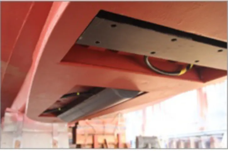
a) L3-‐ELAC Nautik SBE 3050 Multibeam
The SeaBeam SBE 3050 multibeam system by ELAC Nautik is built into a gondola fixed underneath the hull of POSEIDON, which gives space for the transducers and provides best protection against bubble disturbances. Due to size limitations the transducer arrays were chosen in a 1.5° by 2° dimension. The SeaBeam 3050 is the latest generation of mid and shallow water multibeam bathymetric sonar systems from L-‐3 Communications ELAC Nautik GmbH. The new multi-‐ping technology of the SeaBeam 3050 allows a higher maximum survey speed without loosing 100% bottom coverage by creating two swaths per ping cycle. The system operates in the 50 kHz frequency band in water depths ranging from 3 m below the transducers to approx. 3,000 m.
Fig.4.a.1: Gondola with Multibeam transducers
The system can be utilized at survey speeds of up to 14 knots. It has an across-‐ship swath wide of up to 140 degrees. A maximum of 386 reception beams is provided for each multi-‐ping. The SeaBeam 3050 uses a transmit technique, which fully compensates for vessel pitch and yaw motion, recorded by the CodaOctopus motion sensor F180 (see below) and which is integrated into the system’s network. The compensation is achieved by splitting the transmit fan in several sectors which can be steered individually. This technique achieves full motion compensation and guarantees a stable straight coverage under the vessel. The SeaBeam 3050 generates sonar data for wide-‐swath contour charts, backscatter data for seabed sediment classification, raw data for water column imaging (WCI) and sidescan data for side-‐scan images.
Figure 4.a.2: Data flow of the sonar system, motion sensor and operating PC.
The F180 Inertial Attitude and Positioning System from CodaOctopus is integrated into the sonar system network, making precision measurements of vessel attitude (including heading), dynamics and geographical position for use in compensating the vessel motion for hydrographic surveying. The system is a multi-‐sensor system consisting of an inertial measurement unit (IMU), built up of three solid-‐state gyros and three inertial grade accelerometers, and two survey grade GPS receivers.
b) Multichannel 2D seismic streamer
The 2D standard multichannel seismic streamer consisted of modular GeoEel streamer segments. Each segment provides 8 hydrophone groups and is connected to the streamer chain via a digitiser bottle, which adds the actual data to the entire stream of signals send across the streamer via Ethernet. For the cruise five 25 m long oil filled sections with a 3,25 m group interval, 12 oil filled sections of 12.5 m length (1.5 m group interval) and three solid state sections of 12.5 m length (1.5 m group interval) composed to an active length of 312.5 m with 160 channels (Fig. 4.b.1). Nominal streamer depth of 2 m was controlled by two birds, one at the stretch section, the second at 250 m offset.
Only the second A/D bottle of the solid state streamer sections was deployed with wooden float supports until final deployment with wooden floats on all segments.
Figure 4.b.1: Streamer winch with 300 m active sections on the drum; the single
hydrophone nodes of the deep towed streamer rest on the deck to the right
c) Mini-‐GI Airgun and compressor
As R/V POSEIDON is not equipped with a seismic compressor two Sauer compressors (WP3441-‐100 and WP3440) were rented for the cruise. In order to provide sheltered storage room a 10’ container was stowed at the end of the port side working deck (Fig.
4.c.1). It was planned to connect both compressors through a switchboard (GEOMAR) to the port diesel generator of the vessel. Unfortunately it turned out that the fuses in the switchboard acted to fast on the switch on power peak. Therefore the WP3440 compressor was directly connected to a 360 V power socket at the aft deck. The
WP3441-‐100 device could be connected to the vessels diesel generator by use of the single 440 V socket of the switchboard. The container holds two 200 l pressure bottles as buffer device as well. With outside air temperatures of up to 19° C the compressors operated at max. 50° C. For warmer outside conditions additional active air exchange need to be installed in the container.
Active seismic signals were generated by the use of a Mini-‐GI Airgun towed at 1 m depth.
The gun was operated with volume reducers providing 15 cinch volume for injector and generator. Nominal air delivery of the compressors is 52 m3/hr (WP3441-‐100) and 29 m3/hr (WP3440) both at 350 bar. Firing the Mini-‐Gi airgun at 5 sec. interval for the surface streamer operation resulted in a gun pressure of about 178 bar during most of the time. With the deep towed streamer adjustment of streamer configuration, recording delay and recording duration resulted into a shot interval of 7 sec, which enabled 180 bar pressure. For the last regional seismic profile the Mini-‐Gi was operated without volume reducers (30 / 30 cinch) and the shot interval needed to reduced to 8 sec. to enable 150 bar pressure. During the first shots with the different gun volumes test for the injector delay were undertaken. It was found that 20 ms delay provides the best compromise between sharpness of the source signal and bubble suppression.
Figure 4.c.1: 10’ compressor container installed at R/V POSEIDON
d) DeepTow Multichannel Streamer
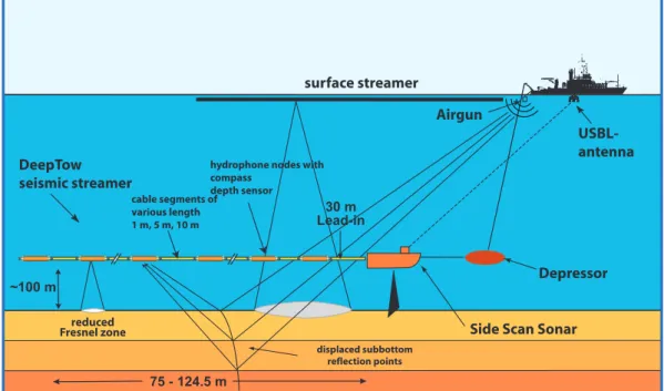
With standard surface streamers the lateral resolution is reduced with increasing water depth. Using a deep-‐towed streamer could provide a constant improved resolution as the receiver array is towed about 100 meters above the seafloor (Fig. 4.d.1). Due to the
drag of the deep sea cable in the water the tow fish is expected to be 2 to 2.5 times the water depth offset behind the vessel. Operating a standard GI airgun as sound source this allows undershooting of high reflective seafloor elements (e.g. carbonate crusts).
Therefore the DeepTow provides the opportunity to resolve reflection interfaces in regions where standard surface streamers can image blanking areas only. In areas with very rough topographic seafloor conditions the proximity to the seafloor should reduce the interaction of seafloor and shallow reflection energy with signals received from side echoes. With the source still at the sea surface and the receiver deployed at depth the raypath for the sound emission is no longer symmetric and hence the concept of CDP stacking does not hold any more. Therefore full waveform migration need to be applied to integrate all streamer channels into one seismic section.
Figure 4.d.1: Scetch of the DeepTow system with multichannel streamer and Sidescan, during POS-‐484 the streamer was operated without the sidescan sonar
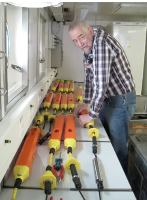
The deep towed multichannel streamer is a custom made development, designed by companies SEND Off-‐shore, Hamburg, and KUM, Kiel. It comprises of single hydrophone modules and modular cable connections (Fig. 4.d.2). From a so-‐called Top-‐PC (TPC) Ethernet connections to the Bottom-‐PC (BPC) in the tow fish and the GeoEel seismic QC recording system from Geometrics are distributed. In addition the sidescan sonar PCs in the tow fish and on board the vessel (not available for POS-‐484) can be connected via the TPC, BPC and the modems of the telemetry system (Fig.
4.d.3). The TPC runs a control program for the deep towed streamer. Here all parameters (shot interval, recording delay, record length, etc.) are specified and submitted to the streamer and the recording system. Moreover the control program displays heading and depth distribution of the hydrophones and other statistical system information. During
Airgun
Side Scan Sonar DeepTow
seismic streamer
USBL- antenna
Deep Tow Seismic Streamer & Side Scan Sonar System
surface streamer
reduced Fresnel zone
displaced subbottom reflection points
~100 m
Lead-in30 m
75 - 124.5 m
Depressor
hydrophone nodes with compass
depth sensor cable segments of various length 1 m, 5 m, 10 m
Figure 4.d.2: Photgraph of the streamer hydrophones and cable segments during setup of the multichannel chain.
profiling a GPS based time code is interpreted to generate the wanted shot interval and to distribute the trigger signal to all external systems and the streamer at depth.
Depending on the bandwidth of the towing cable a certain number of hydrophone data can be transmitted real-‐time via the cable on board. The hydrophone nodes are equipped with a compass and a depth sensor. During operation the USBL system POSIDONIA is used to track the position of the towfish. From this data base exact positions for each hydrophone at each shot time can be calculated.
Figure 4.d.3: Overview of the data connections within the DeepTow control system During the first deployment test activation of the streamer failed. It turned out that three cables and nodes were questionable and need to be removed from the chain. A
second trial failed after some 20 minutes, when the streamer could not be initiated any more. Upon system check four coils were identified on the streamer control board to be not longer in good shape. After replacement the system worked stable and profiling could take place.
5. Work performed and results
Within the second part of the cruise P-‐484 MARSITE 2D surface and deep towed multichannel seismic data have been acquired. Multibeam data were acquired on all courses with WCI data recording switched on at all tracks. Figure 6.1 shows an overview of the working areas and the applied techniques.
Figure 5.1: Overview of the survey area at the Palinuro volcanic complex
Yellow stars: OBS; red lines: DTMCS; black lines: 2D MCS grid on top of the western Palinuro segment; blue lines: 2D MCS profile connecting western, central and eastern segment; dashed black line: TIR10 URANIA seismic profile
a) L3-‐ELAC Nautik SBE 3050 Multibeam
One prerequisite of multibeam bathymetry surveys is the exact knowledge of the water sound velocity. Therefore we deployed a CDT at 39° 24’ N / 14° 42’ E down to a water depth of 2000 m, which covers the foreseen survey depth.
CDT at 39° 24’ N / 14° 42’ E
The multibeam system was operated on all courses during the cruise. Although no gas bubble emission was expected the WCI option was switched on, but did not reveal any signals.
The processed data could be gridded at 15 m cell size with some slight scatter remaining from automatic swath width adaption. A good compromise between clear reading and resolution is a 30 m grid size, which will extend the available EM710 database. Post-‐
cruise editing is believed to clean the data and allow for < 30 m gridding.
Bathymetric map of the Palinuro volcanic complex acquired during seismic profiling of cruise POS-‐484 (gridsize 30 m).
b) 2D GeoEel Multichannel Surface Streamer
Aim of the seismic investigations was to image the western segment of Palinuro the first time. Special emphasis was dedicated to the NE cone at 39° 32’ N / 14° 42’ E where massive sulfides had been drilled before. Six OBS were deployed along a NE-‐SW oriented profile perpendicular to the elongation of the cone. A total of 14 seismic profiles were acquired covering the cone in various azimuths (Fig. 5.1). Additional lines were dedicated to further investigate the entire structure of the western segment. The half circle orientation of the remaining cones and ridges, which border the western segment, look like they had formed the rim of an caldera structure in earlier times. Extension of the seismic lines to the south should clarify if relevant sub seafloor structures could be found.
The remaining time at the end of the cruise was used to acquire a seismic line along the peaks of the central and eastern segment of Palinuro. This profile links to the TIR10 cross profile.
c) DeepTow Multichannel Streamer
Usually the deep towed streamer is operated about 100 m above seafloor in order to clearly separate the first arrival of the source signal from the seafloor reflection. Due to the strong topography of the Palinuro such an attempt would require permanent winch operation. Consequently the gun – streamer offset would continuously be changed and cause additional deviations of the streamer nodes, causing major difficulties during data processing. Therefore it was decided to operate the streamer in a continuous depth
adopted to the shallowest structure on the foreseen course. With a depth of about 500 m at the peak of the NE cone in the western segment the towing depth was set to 400 m, resulting in a deployed length of about 800 m for the deep sea cable. Due to the required 1 nm radius during turns between following lines the available time allowed to collect 4 profiles across the structure (Fig. 5.1). Due to the source – receiver geometry deep towed streamer records are very sensible for diffracted energy when approaching steeply ascending seafloor. Diffraction hyperbola will cover reflection events from shallow interfaces, while sections departing from such slopes stay clear of this noise. As the shallow mineralised horizons are the main target of this investigation it was decided to record all deep towed profiles in reversed direction.
6. Acknowledgements
Our thanks go to the captain and crew of R/V POSEIDON. The outstanding support of the crew was a major contribution to the successful operation. Financial support of cruise P-‐
484 was provided through GEOMAR budgets and the EU funded project “Blue Mining -‐
Breakthrough Solutions for Mineral Extraction and Processing in Extreme Environments” (604500).
7. Appendix
a) OBS deployment
Instr. Lat. Long. Depth Remarks
OBS 1 39°31,172 14°42,752 1120 -‐36 ms / 4.3 GB OBS 2 39°31,686 14°42,042 941 0.1 ms / no data
OBS 3 39°32,185 14°42,265 565 -‐11 ms / ?? GB / seismometer not deployed OBS 4 39°32,458 14°42,401 611 10 ms / 4.1 GB
OBS 5 39°32,714 14°42,537 634 no data
OBS 6 39°33,192 14°42,790 990 -‐21 ms / 4.1 GB
b) 2D GeoEel streamer configuration
No. Bottle Section length Bird LeadIn 36 m off stern
Heck
Stretch 25 m X
1 DG1473 AR1184 25
2 DG1270 25
3 DG1721 AR1185 25
4 DG1271 25
5 DG126L 25
6 DG1232 AR1052 12,5
7 DG1182 AR1096 12,5
8 DG1277 AR1069 12,5
9 DG1102 ARE1111 12,5
10 DG1529 12,5
11 DG1267 AR1102 12,5
12 DG1266 AR1079 12,5
13 DG1242 ARE1073 12,5
14 DG1112 AR1161 12,5 X
15 DG1235 AR1157 12,5
16 DG1266 AR1081 12,5
17 DG1246 AR1001 12,5
18 DG1774 GS0249 12,5
19 DG1685 GS0XXX 12,5
20 DG1683 GS0247 12,5
c) DTMCS configuration
No. Node Cable
length
Lead in 40 m
1 2010010 1 m
2 2010022 1 m
3 2010020 10 m
4 2010039 1 m
5 2010015 1 m
6 2010004 5 m
7 20090001 1 m
8 2010036 1 m
9 2010008 3 m
10 2010006 1 m
11 2010032 1 m
12 2010028 1 m
13 2010014 3 m
14 2010041 1 m
15 2010037 1 m
16 2010023 1 m
17 2010012 3 m
18 2010021 1 m
19 2010026 1 m
20 2010025 1 m
21 2010027 3 m
22 2010035 1 m
23 2010018 1 m
24 2010013 1 m
25 2010011
8. References
Colantoni, P., F. Lucchini, P. L. Rossi, R. Sartori, and C. Savelli (1981), The Palinuro volcano and magmatism of the southeastern Tyrrhenian Sea (Mediterranean), Marine Geology, 39(1–2), M1-‐M12.
Ligi, M., L. Cocchi, G. Bortoluzzi, F. D'Oriano, F. Muccini, F. C. Tontini, C. E. J. de Ronde, and C. Carmisciano (2014), Mapping of Seafloor Hydrothermally Altered Rocks Using Geophysical Methods: Marsili and Palinuro Seamounts, Southern Tyrrhenian Sea, Econ Geol, 109(8), 2103-‐2117.
Monecke, T., S. Petersen, K. Lackschewitz, M. Hügler, M. D. Hannington, and J. B. Gemmell (2009), Shallow Submarine Hydrothermal Systems in the Aeolian Volcanic Arc, Italy, Eos, Transactions American Geophysical Union, 90(13), 110-‐111.
Passaro, S., G. Milano, C. D'Isanto, S. Ruggieri, R. Tonielli, P. P. Bruno, M. Sprovieri, and E.
Marsella (2010), DTM-‐based morphometry of the Palinuro seamount (Eastern Tyrrhenian Sea): Geomorphological and volcanological implications,
Geomorphology, 115(1-‐2), 129-‐140.
Petersen, S., et al. (2014), Drilling Shallow-‐Water Massive Sulfides at the Palinuro Volcanic Complex, Aeolian Island Arc, Italy, Econ Geol, 109(8), 2129-‐2158.