PHOTON DIAGNOSTIC FOR THE SEEDING EXPERIMENT AT FLASH
∗F. Curbis
†, A. Azima, J. Boedewadt, H. Delsim-Hashemi, M. Drescher, T. Maltezopoulos, V. Miltchev, M. Mittenzwey, J. Rossbach, R. Tarkeshian,
M. Wieland, University of Hamburg, Germany
S. Duesterer, J. Feldhaus, T. Laarmann, H. Schlarb, DESY, Hamburg S. Khan, DELTA, Dortmund
A. Meseck, Helmholz-Zentrum Berlin, Berlin, Germany R. Ischebeck, PSI, Villigen, Switzerland
Abstract
Starting from next year the technical feasibility of a di- rect seeding scheme at 30 and 13 nm will be studied at the Free-electron LASer in Hamburg (FLASH). During a ma- jor shutdown the SASE-FEL facility will be upgraded and it is planned to install in addition a high-harmonic genera- tion (HHG) seed laser, a new chain of 10 m variable gap un- dulators and a dedicated commissioning beamline for pho- ton diagnostics and pilot time-resolved pump-probe exper- iments. Besides demonstrating successful seeding at short wavelength, the project aims for time resolution in the 10 fs range to study ultrafast processes by combining the natu- rally synchronized FEL and optical seed laser pulses.
After the extraction of the radiation in a magnetic chicane, a short branch will accommodate intensity and beam moni- tors and a high-resolution spectrometer. The intensity mon- itor detects scattered photons from a gold mesh on a shot- to-shot basis using micro-channel plates (MCP) and XUV diodes. It is designed to detect photons several orders of magnitude apart influx, i.e. spanning the wide range from spontaneous emission up to the seeded FEL radiation at gigawatt power level. Simulations of this device are pre- sented as well as calibration measurements carried out at FLASH.
INTRODUCTION
The free-electron laser FLASH at DESY is working in the SASE regime producing sub-10 fs XUV pulses down to 6.5 nm [1]. The facility is based on a 1 GeV supercon- ducting linear accelerator and a 27 m-long chain offixed- gap undulators. During a major upgrade of the machine starting in autumn 2009 several new components will be installed in order to improve the shot-to-shotfluctuations and the longitudinal coherence and to increase the electron energy to 1.2 GeV. Thus, after the shutdown FLASH will deliver intense photonflux close to the carbon K-edge at 284 eV (4.4 nm). A third harmonic cavity [2] will allow to produce 200 fs long electron bunches (few kA of peak cur- rent) and thus longer radiation pulses where more modes
∗This work is supported by the Federal Ministry of Education an Re- search under contract 05 ES7GU1
†francesca.curbis@desy.de
will contribute to the FEL radiation. Another way to im- prove the longitudinal coherence of the radiation is to seed the electron beam with high-order harmonics of an optical laser generated in a gas target and to use undulators as an amplifier. Since direct seeding at 160 nm has been already achieved at SCSS [3], the aim of sFLASH is to demonstrate seeding at shorter wavelengths and in addition to use this radiation for pump-probe experiments in a dedicated beam- line [4]. The layout of the FLASH facility is illustrated in Fig. 1 with emphasis on the forthcoming installations.
GENERAL LAYOUT OF SFLASH The HHG Source
The laser system generating ultrashort pulses is located next to the FLASH tunnel. After the compression stroke, a beamline with one focusing mirror and three flat mir- rors lets the HHG pulses go into the tunnel. The remote control of mirrors allows the steering of the beam in both planes. The mirrors are mounted on a translation stage that enables to select different wavelengths using different por- tions of the mirrors with different coatings. Three focusing lengths are foreseen in order to optimize the HHG genera- tion. The challenge is to provide HHG pulses of 1 nJ energy that according to simulation is sufficient to reach saturation at 13 nm<λ 30nm within the 10 m undulator length. Thus the losses have to be minimized and the pointing stability of the optical laser as well as other HHG parameters (pulse energy, chirp, frequency, ...) need careful optimization.
The HHG source will be locked to the synchronization sys- tem using an optical cross correlator [5]. For reliable op- eration the relative jitter between HHG pulses and 200 fs- electron bunches should not exceed 40 fs rms and an intra- pulse train feedback system has been developed [6]. The temporal overlap will be achieved using a streak cam- era [7].
Electron Beamline and Undulators
A 40 m long section of FLASH will be completely re- modeled to accommodate the 10 m variable-gap undulators for the sFLASH experiment: three new 2 m-long undula- tors (PETRAIII type, 31.4 mm period) and an old 4 m-long undulator (period 33 mm) previously used at PETRAII syn-
<
S
THOB05 Proceedings of FEL2009, Liverpool, UK
FEL Technology II: Post-accelerator 754
315 m Laser
RF Gun
Collimator
ExperimentsFEL
sFLASH
3rd harmonic
cavity
Figure 1: Layout of the FLASH facility after the shutdown. A third harmonic cavity will be installed before thefirst bunch compressor and the section between the collimator and the SASE undulators will accommodate the sFLASH components.
chrotron light source. The vacuum chamber within the un- dulators has been design in order to maximize the range of achievable wavelengths [8]. Each intersection between undulators will include a quadrupole, a phase shifter and beam-position monitors. A further diagnostic is foreseen to help looking for the transverse overlap. Placed at the end of each undulator, the diagnostic blocks include a wire scan- ner with MCP detector, an OTR screen and a Ce:YAGflu- orescent screen. The optics of the beamline is such that the undulators are protected by the upstream collimator against detrimental radiation.
PHOTON BEAMLINE
After the undulator section, the electron beam is ver- tically displaced by a magnetic chicane and the FEL ra- diation is extracted by a deflecting mirror. The photon beamline continues with thefirst diagnostic block equipped with a Ce:YAG screen and two cameras, then a second switching mirror allows to send the radiation either into the diagnostic branch (that includes intensity monitor and XUV-spectrometer) or into the experimental hutch outside the tunnel where time-resolved pump-probe studies can be performed with high temporal resolution. A port for the alignment laser is placed before thefirst diagnostic block.
The technical drawing of the diagnostic branch is shown in Fig. 2.
Figure 2: Layout of the diagnostic branch. The FEL radia- tion, coming from left, is deflected by thefirst mirror, then passes through the diagnostic unit. After that a further mir- ror allows to send the beam either to the XUV-spectrometer or to the experimental hutch.
The mirrors are plane amorphous carbon coated silicon
substrates with grazing incidence at 5◦. The reflectivity at this angle is typically better than 85%. A portion of the mirros has larger roughness resulting in the attenuation on the detectors.
Spectrometer
The XUV-spectrometer [9] (1 m focal length, gold- coated grating blazed at 20nm and 3◦ angle of incidence) will be located inside the FLASH tunnel. This instrument is capable to measure spectra on a single-shot basis with large dynamical range. A 40 mm MCP detector is mounted perpendicular to the exit beam of the instrument tangent to the Rowland circle and afiber taper is connected to the CCD for data readout. The CCD can be scanned along the Rowland circle to position any wavelength between 1 nm and 35 nm at the center of the detector. The resolution of the system at 13 nm and 30 nm is aboutλ/Δλ=1000 (see Fig. 3). The undulator gap will be set with the help of the spectrometer in order to match the spontaneous emission wavelength with the seed laser wavelength.
Figure 3: Spectrum at 30.8 nm which demonstrates the res- olution of the spectrometer [9].
INTENSITY MONITOR
The measure of the gain curve is essential in order to fully characterize the radiation generated in the seeding process. For this purpose a detector being able to span over a large range of intensity is necessary and we adopted
Proceedings of FEL2009, Liverpool, UK THOB05
FEL Technology II: Post-accelerator 755
a concept already tested at FLASH [10]: the detection of scattered FEL radiation from a metal mesh using MCPs.
Since the wavelengths to detect are between 13 and 30 nm the most suitable candidate in terms of reflectivity is gold.
The dynamical range of this detector should span from the spontaneous undulator radiation to the seeded FEL in sat- uration, i.e., six-seven orders of magnitude in photonflux.
In order to adjust the amplification of the detected signal, the MCP voltage is set accordingly but this gives a dynamic range of only four orders of magnitude. To overcome this problems different geometries were tested performing sim- ulations with the code ZEMAX [11] taking into account tabulated values for the reflectivity of gold at 30 nm [12].
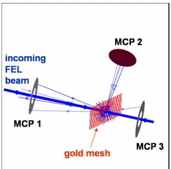
The gold mesh is placed at the center of the detector at 45◦ with respect to the FEL beam. Three MCPs are used: one is at 45◦with respect to the mesh (90◦with respect to the FEL beam), the other two MCPs have a hole in the middle to be place on axis with respect to the FEL beam. Thefirst holed MCP detects the radiation scattered backward from the mesh and the second holed one detects the radiation scattered forward (see Fig. 4).
Figure 4: Schematic layout of the intensity monitor. The detector contains 3 MCPs mounted at different geometry with respect to the photon beam in order to increase the dynamic range of detection.
Due to the geometry, the detection efficiency of each MCP is different at the same photon energy, hence increas- ing the dynamical range of detection. Simulation show that by changing the distance from the mesh for each MCP it is possible to change the detection efficiency. Three different configurations were tested and taken into account in Table 1 starting from the same number of photons. Experimentally it is possible tofind an overlap in the detection region for certain voltage settings of the MCPs. Once the overlap is found it is possible to switch from one MCP to the other to
follow the gain curve. Since the efficiency depends also on the mesh which is used, two different meshes (open area 65% and 44%) are mounted on a translation stage that al- lows to select the most suitable one depending on the pho- tonflux.
Table 1: Detection efficiency at different distances of the MCPs from the mesh.
configuration i ii iii
MCP 1 2.6% 1.1% 0.6%
MCP 2 4.7% 2.4% 1.5%
MCP 3 0.04% 0.07% 0.16%
Calibration Measurements
The intensity monitor has been installed at the BL1 FLASH beamline for test measurements [13]. This beam- line has been chosen because the transverse dimension of the radiation is similar to the expected beam size at the position where the intensity monitor will be installed at sFLASH (about 500μm FWHM). Dedicated electronics for data acquisition has also been tested. The readout of the MCP signal consists of a preamplifier followed by a stretcher, that lengthen the short signal (usually about 1 ns).
The output of the stretcher is send to an ADC which is read by the DAQ.
4 6 8 10 12 14 16 18 20 22
0.05 0.1 0.15 0.2 0.25 0.3 0.35 0.4 0.45 0.5
Energy [μJ]
MCP signal
Figure 5: Linear plot of MCP 2 signal versus absolute en- ergy of the beam (measured by the GMD [14]). The preci- sion of the absolute energy calibration is about 20%.
We simulated the amplification curve of sFLASH atten- uating the SASE beam from theμJ range down to the pJ range by means of a combination of the gas attenuator [14]
and two aluminumfilters (thickness 200 and 137 nm). The last measurement has been carried out detuning SASE to have only spontaneous emission from the undulator which is similar to the starting point of the commissioning phase in the sFLASH project. The wavelength used was 13.7 nm.
THOB05 Proceedings of FEL2009, Liverpool, UK
FEL Technology II: Post-accelerator 756
We measured the MCP output signal for different high- voltage settings and we recorded the shot-to-shot energy of the pulses measured by the gas monitor detector [14]. The precision of the gas monitor detector itself is about 20%.
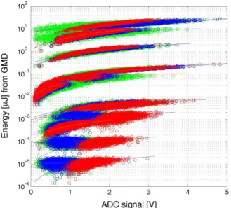
In Fig. 5 the output signal of one MCP versus the beam energy for one voltage setting is shown. Combining all the measurements with different attenuation of the beam and different voltage settings, it is possible to retrieve the required dynamical range with this detector. In Fig. 6 it is shown that this range is 6-7 orders of magnitude.
Figure 6: Cross-calibration of the intensity monitor with energy measurements from the gas monitor detector for dif- ferent voltage settings.
CONCLUSIONS
The exploration of the technical feasibility of seeding an FEL in gap-tunable undulators at short wavelength (30 nm and 13 nm) with a stability suited for user operation will have an enormous impact on the design of future upgrades or extensions of the FLASH facility in particular as well as on the design of future FELs world wide in general. Dur- ing the commissioning period the perfect performance of the diagnostic tools will be essential for the success of the sFLASH project. The spectrum will be measured on shot- to-shot basis with a resolution of 0.03 nm at 30 nm. The intensity monitor has already been tested with a FEL beam and is able to detect a large dynamic range of photonflux, from spontaneous emission to the saturated regime span- ning several orders of magnitude.
ACKNOWLEDGEMENTS
We thank many groups at DESY (among them HASY-
REFERENCES
[1] W. Ackermann et al., Nature Photonics 1, 336 - 342 (2007) [2] K. Floettmann et al., “Generation of Ultrashort Electron
Bunches by cancellation of non-linear distortions in the lon- gitudinal phase space”, TESLA-FEL-2001-06
[3] G. Lambert et al., Nature Physics 4, 296 - 300 (2008) [4] V. Miltchev et al., “TECHNICAL DESIGN OF THE XUV
SEEDING EXPERIMENT AT FLASH”, these proceedings (WEPC05)
[5] S. Schulz et al., Proc.EPAC’08, Genova, 3366
[6] F. Loehl et al., Proc. EPAC’08, Genova, 3360; F. Loehl et al., Proc. EPAC’06, Edinburgh, 2781
[7] R. Tarkeshian et al., Proc. FEL’08, Gyeongju, 363
[8] M, Altarelli et al., “The European X-ray Free Electron Laser”, Technical Design report, DESY 2006-097
[9] McPherson 248/310G;http://www.mcphersoninc.com [10] L. Bittner et al., Proc. FEL’07, Novosibirsk, 334
[11] http://www.zemax.com
[12] LBL database:http://henke.lbl.gov/
[13] R. Treush, HASYLAB annual report, DESY, Hamburg, 2005, 159-164
[14] K. Tiedtke et al., “The soft x-ray free-electron laser FLASH at DESY: beamlines, diagnostics, and end stations”, New J.
Phys. 11 023029
LAB, MPY, FLA, MCS, MIN, MKK, MVS) for their support in this project.
Proceedings of FEL2009, Liverpool, UK THOB05
FEL Technology II: Post-accelerator 757
![Figure 3: Spectrum at 30.8 nm which demonstrates the res- res-olution of the spectrometer [9].](https://thumb-eu.123doks.com/thumbv2/1library_info/3774211.1512973/2.889.87.432.794.961/figure-spectrum-nm-demonstrates-res-res-olution-spectrometer.webp)