TECHNICAL DESIGN OF THE XUV SEEDING EXPERIMENT AT FLASH
∗V. Miltchev†, A. Azima, J. B¨odewadt, F. Curbis, M. Drescher, H. Delsim-Hashemi, T. Maltezopoulos, M. Mittenzwey, J. Rossbach, R. Tarkeshian, M. Wieland, Uni HH, Hamburg
S. D¨usterer, J. Feldhaus, T. Laarmann, H. Schlarb, DESY, Hamburg A. Meseck, Helmholz-Zentrum Berlin, Germany
S. Khan, DELTA, Dortmund, Germany R. Ischebeck, PSI, Villigen, Switzerland Abstract
The Free-electron-laser at Hamburg (FLASH) oper- ates in the Self-Amplified Spontaneous Emission (SASE) mode, delivering to users photons in the XUV wavelength range. The FEL seeding schemes promise to improve the properties of the generated radiation in terms of stability in intensity and time. Such an experiment using higher harmonics of an optical laser as a seed is currently un- der construction at FLASH. The installation of the XUV seeding experiment (sFLASH) is going to take place in fall 2009. This includes mounting of new variable-gap undu- lators upstream of the existing SASE-undulators, building the XUV-seed source as well as installation of additional photon diagnostics and electron beam instrumentation. In this contribution the layout of sFLASH will be discussed together with the technical design of its major components.
INTRODUCTION
Currently FLASH operates in the SASE regime and pro- duces EUV pulses of sub-10 fs duration [1]. Due to its start- up from noise, the SASE radiation consists of a number of uncorrelated modes resulting in reduced longitudinal co- herence and shot-to-shotfluctuations (about 18 % rms [1]) of the output pulse energy. One possibility to decrease the magnitude of these pulse energy shot-to-shot fluctu- ations is, with the help of a 3.9 GHz RF cavity [2], to produce much longer (∼200 fs) radiation pulses, so that more modes contribute to the FEL output. However, in this case the increased EUV pulse length might not fit to the needs of ultrafast time resolved experiments. An alterna- tive is to operate FLASH as an amplifier of an injected seed from a high harmonic generation (HHG) source. This ap- proach gives several benefits compared to SASE. It enables to achieve higher shot-to-shot stability at a GW-power level with a pulse duration given by the seed pulse of the order of 20 fs FWHM. The longitudinal coherence is expected to be greatly improved. The FEL output is synchronized with the external seed laser, thus enabling pump-probe experiment with increased temporal resolution.
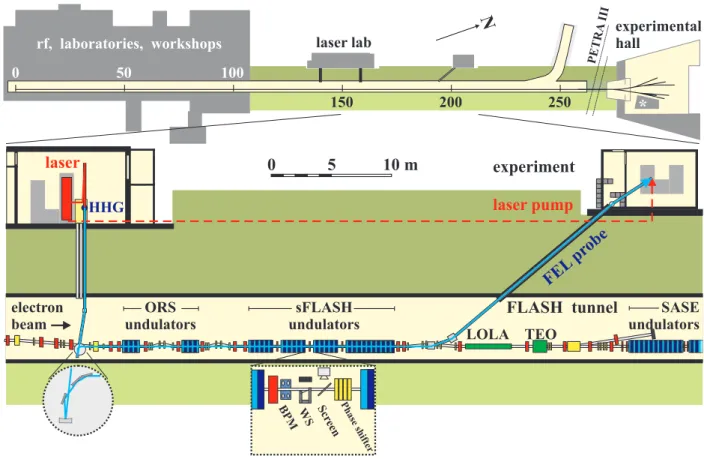
As sketched in Fig.1, sFLASH will be installed at the end of the linac, upstream of the existingfixed-gap SASE-
∗Supported by the Federal Ministry of Education and Research of Ger- many under contract 05 ES7GU1
†velizar.miltchev@desy.de
undulators. With the help of a dedicated optical beamline, the HHG seed will be inserted through the collimator sec- tion, making use of the electron beam offset of about 20 cm.
After amplification in the sFLASH variable-gap undula- tors, the output radiation is separated from the electrons by means of a mirror mounted in a small magnetic chicane downstream. The photons are then reflected towards the experimental area outside the FLASH tunnel. An experi- ment recently performed by a French-Japanese collabora- tion at the SPring-8 Compact SASE Source [3] has suc- cessfully demonstrated HHG seeding at 160 nm. The goal of sFLASH is to study the technical feasibility of the seed- ing at shorter wavelengths and how to reliably realize it for user operation.
ELECTRON BEAMLINE General Requirements
The aim for a stable seeded operation in the 30-13 nm range imposes certain requirements for the design of the experimental layout and for the electron beam parameters.
It is mandatory to obtain a reproducible six-dimensional, {x, y, x, y, t, λ}, overlap between the seed and the elec- tron bunch. Therefore, the beamline must include proper diagnostics and instrumentation to maintain the overlap within the desired tolerances, which according to the stud- ies performed with GENESIS [4, 5], are of the order of 30μmand20μradin both transverse planes. In order to minimize the impact of the timing jitter, the electron bunch length should be of the order of 260 fs rms, even though the state-of-the-art synchronisation system (see below) can re- strict the jitter to less than 40 fs rms. Such operation mode can be realized only after the installation of the 3rd har- monic (3.9 GHz) RF cavity. sFLASH has to run in parallel to and without disturbing the SASE operation. The SASE- undulators arefixed-gap devices and the SASE wavelength, given by the electron energy, is defined by the users. There- fore, for tuning the resonant wavelength of sFLASH one needs variable gap undulators. Moreover, the total undula- tor length has to assure that saturation can be reached at all seeding wavelengths. Finally, since the HHG seeding will share the same beamline with other setups (e.g. ORS [6]
and LOLA[7]), one has to provide compatibility between the different experiments.
Proceedings of FEL2009, Liverpool, UK WEPC05
FEL Technology II: Post-accelerator 503
laser HHG
LOLA TEO ORS
undulators electron
beam
SASE undulators sFLASH
undulators
FLASH tunnel experiment laser lab
rf, laboratories, workshops
experimental hall
PETRA
N III
0 50 100
150 200 250 *
0 5 10 m
laser pump
FEL probe
Phase shifter Scr
een BPM WS
Figure 1: The FLASH facility (top) comprises a 260 m long tunnel housing the linac and the SASE-undulators, followed by an experimental hall. A 40 m long section (bottom) upstream of the SASE-undulators will be modified in order to install beam line components for the XUV seeding experiment. Seed pulses from the HHG source in the building adjacent to the FLASH tunnel will be aligned to the electron beam downstream of the last dipole of the energy collimator (left).
At the undulator exit, the FEL radiation is reflected towards an experimental hutch. A fraction of the optical drive laser energy will be sent directly to the hutch for pump-probe applications (dashed line). The dashed bordered boxes show detailed views of the seed incoupling and the undulator intersections.
Beamline Layout
The final layout of the electron beamline in the seed-
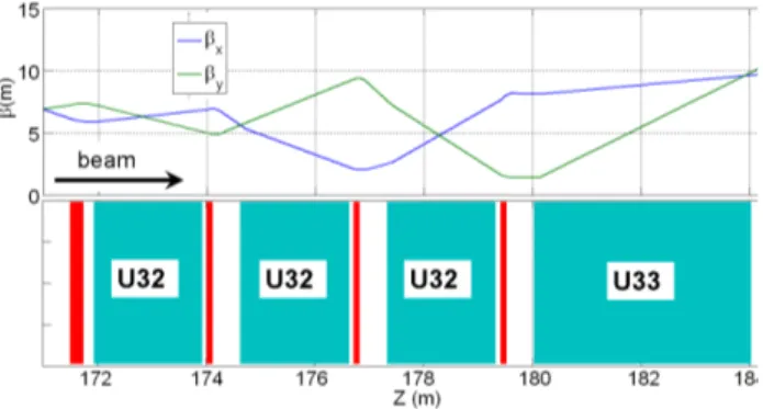
ing section is illustrated in Fig.2. It consists of four pla- nar variable-gap undulators of 10 m total length, separated by 70 cm intersections. As shown in Fig.3, the transverse focusing, accomplished by quadrupoles placed in-between the undulator segments, allows an average β-function of the order of 6 m. The electron beam diagnostics will be realized using wire scanners, optical transition radiation (OTR) and Ce:YAG screens and beam position monitors.
The wire scanners and screen stations, together with ad- ditional instrumentation (BPM, microchannel plates), will be compacted in a common diagnostic block. The idea is to make these devices usable for both electron beam and HHG radiation diagnostics. This feature is critical forfind- ing and keeping the overlap between electrons and the seed.
From this point of view the two diagnostic blocks located before and after thefirst undulator (see Fig.2) are of partic- ular importance. The three electromagnetic phase shifters will compensate the shift between the phase of the elec- tron transverse velocity and the electromagneticfield, in-
troduced by the drift between undulators. Figure 3 shows theβ-function along the seeding beamline calculated with the help of the code ELEGANT [8]. The apertures of both
Figure 2: Schematic layout of the electron beamline in the seeding section.
the collimator (located upstream of the sFLASH undula- tors, see Fig.1) and the vacuum chamber have been consid- ered in the design of the electron optics in order to assure full transmission without losses.
WEPC05 Proceedings of FEL2009, Liverpool, UK
FEL Technology II: Post-accelerator 504
Figure 3:β-function along the sFLASH beamline
sFLASH Undulators
As sketched in Fig.2 sFLASH comprises a 10 m long undulator section. Unlike the present FLASH undulators, these will be variable gap devices. Three 2 m long U32 will be followed by a 4 m long U33 undulator. The lat- ter is a previously decommissioned device which can be reused for sFLASH after refurbishment as described else- where [9]. In Table 1 undulator parameters are listed. The
Table 1: Parameters of sFLASH Undulators [9]
U32 U33
Min. gap (mm) 9.0 9.0
Period length (mm) 31.4 33
No. of poles 120 240
Length (m) 2 4
Peakfield (T) 1 1.07
sFLASH undulator chamber uses a modification of the Eu- ropean XFEL design [9] (see Fig. 4). Taking into consider- ation the vertical size of the vacuum chamber (8.6 mm) and the minimum desired undulator gap size (9 mm), a sophis- ticated support and holder system is prepared to adjust and maintain the position of the chamber within the undulator gap. The development of undulators for PETRA III [10]
Figure 4: Cross-section of the undulator vacuum chamber has been adapted for U32 undulators. Their control system is based on off-the-shelf standard components for indus- trial automation. The gap drive consists of two independent servo axes for each magnet girder to allow for maximum flexibility, e.g. for tapering or beam height adjustment.
Each of the axes is equipped with a multi-turn absolute ro- tary encoder to provide operational reliability even after a
loss of power. In order to achieve the desired accuracy of the order of±1μm, additional linear encoder systems will be mounted at the up- and downstream end of the magnet girders.
The U33 undulator was disassembled in 2007 after more than 10 years of operation in the PETRA II ring. The me- chanics, used for this undulator, was originally developed for the DORIS III wigglers. Its gap measurement system was based on a rotary encoder connected to one of the gear- boxes. Since neither a real-gap measurement system nor a feed-back loop for the gap were available, the undula- tor motion control has been upgraded. Four displacement gauges with micrometer precision were installed at the cor- ners of two jaws. In this design a real-gap measurement tool will be used to reach the same level of accuracy as described for U32s (see [10]).
LASER SYSTEM, HHG SOURCE AND BEAMLINE
HHG occurs when an intense laser field interacts with an atomic gas target. The sFlash seeding source gas target supplied by a pulsed valve is driven by short (35 fs FWHM) 800 nm pulses at a repetition rate of 10 Hz produced by a Ti:sapphire laser system. Depending on different beam fo- cusing schemes, a fraction of the 35mJ pulse energy will be sent into the HHG target chamber. The remaining en- ergy will be used for pump-probe and electron bunch di- agnostic applications. XUV radiation will be created in the gas jet [11] and transported through a differentially pumped vacuum pipe from the laser laboratory into the ad- jacent FLASH tunnel. Here a small diagnostic unit first filters and detects the position of the higher harmonics. Af- ter that two UHV chambers, holding mirrors with different UV coatings (optimized for∼30 nm and∼13 nm), deflect and focus the beam to guide it onto the electron beam axis [12]. To adjust the transverse overlap (angle and position) between the XUV and the electron beam all mirrors are mo- torized. In addition, they are mounted on translation stages to switch between the coatings and - for the focusing mir- ror - different radii of curvature. To enable a longitudinal overlap between the electron bunches and the XUV pulses the laser system will be synchronized with the laser master oscillator of FLASH by an optical synchronization system currently being installed [13]. Together with an intra-pulse train feedback system for the accelerator one expects a rela- tive jitter between the two pulses in the order of 40 fs (rms).
SEPARATION OF PHOTONS AND ELECTRON BEAM
At the exit of the undulator section a magnetic chicane separates the electron and the photon beam vertically. The radiation is directed into a grazing incidence spectrometer using a set of amorphous carbon coated Si plane mirrors that exhibit very high radiation stability [14, 15]. The re- flectivity of the optics at grazing angles of 5◦ is typically
Proceedings of FEL2009, Liverpool, UK WEPC05
FEL Technology II: Post-accelerator 505
ë-sFLASH (nm)
ë-SASE(nm)
Figure 5: The grey area represents the working points where sFLASH reaches saturation for a given set of FLASH SASE-wavelengths and sFLASH-wavelength. A seed pulse energy of 1 nJ is assumed.
larger than 85 %. The spectrometer (McPherson 248/310G, 1-meter focal length, [16]) incorporates an entrance slit ad- justable from 5 to 500μmin front of the gold coated grat- ing with 1200 grooves·mm−1, blazed at 20 nm and 3◦an- gle of incidence. The 40 mm microchannel plate detector assembly is mounted perpendicular to the exit beam of the instrument tangent to the Rowland circle. This way the spectra can be recorded on a single-shot basis with large dynamic range. Data readout is done by afibre taper con- nected to a CCD. The CCD can be scanned along the Row- land circle to position any wavelength between 1 nm and 35 nm at the centre of the detector. The array-detector equipped system will provide approximatelyλ/Δλ= 1000 at 13 nm and 30 nm wavelength position. Finally, the un- dulator gap is tuned so that the undulator radiation and the seed are spectrally matched in the spectrometer. The photon beamline design allows for switching the light be- tween the spectrometer branch and the experimental hutch.
Here, the FEL radiation is combined with part of the natu- rally synchronized optical seed to study the robustness of a seeded FEL at XUV wavelength and the feasibility of dy- namics experiments with improved temporal resolution.
PARALLEL SASE AND SEEDED OPERATION
The XUV seeding experiment is supposed to work in parallel to and at the same accelerator settings as for the normal SASE operation at FLASH. Since FLASH uses fixed-gap undulators the electron beam energy will be de- termined by the SASE-wavelength needed for the exper- iments with photons. Therefore the gap of the sFLASH undulators has to be changed, so that one always matches the seed wavelength with the electron beam energy. Fig.
5 shows the region in the {λSFLASH, λSASE} parameter
space where sFLASH reaches saturation assuming a seed pulse energy of 1 nJ. The black line at the lower side of the gray area represents the limit given by the minimum gap size of the undulator of 9 mm. The horizontal lines indi- cate some SASE wavelengths typically requested for the photon experiments.
ACKNOWLEDGMENTS
Without the help from many groups at DESY (among them FLA, HASYLAB, MCS, MEA, MIN, MKK, MPY, MVS, ZBAU and ZM) the preparation of all sFLASH com- ponents would not be conceivable. Their support is grate- fully acknowledged. The project is supported by the Fed- eral Ministry of Education and Research of Germany under contract No. 05 ES7GU1.
REFERENCES
[1] W. Ackermann et. al. Nature Photonics 1, 336 - 342 (2007) [2] K. Fl¨ottmann et al., TESLA-FEL-2001-06
[3] G. Lambert et. al., Nature Physics 4, 296 - 300 (2008) [4] S. Reiche, Nucl. Instr. and Meth. A 429, 243 (1999) [5] V. Miltchev et al., proceedings FEL’08, Gyeongju,
(TUPPH003).
[6] E.L. Saldin et. al., NIM A 539, 499-526, (2005)
[7] M. Roehrs et’ al., proceedings FEL’06, Berlin, Germany, pp 300-304
[8] M. Borland, ”elegant: A Flexible SDDS-Compliant Code for Accelerator Simulation,” Advanced Photon Source LS- 287, September 2000.
[9] H. Delsim-Hashemi et al., proceedings PAC’09, Vancouver (WE5RFP070)
[10] M. Tischer et al., proceedings EPAC 2008 (2320-2322) [11] Carsten Winterfeldt et.al., Rev. Mod. Phys. 80, 117 (2008) [12] J. Boedewadt et al., proceedings PAC’09, Vancouver
(TU5RFP072).
[13] S. Schulz et al., proceedings PAC’09, Vancouver (TH6REP091).
[14] B. Steeg et al. Applied Physics Letters 84, 657-659 (2004) [15] F. Curbis et al., these proceedings (THOB05)
[16] McPerson 248/310G; http://www.mcphersoninc.com
WEPC05 Proceedings of FEL2009, Liverpool, UK
FEL Technology II: Post-accelerator 506