Ultra-fast FADC Data Aquisition System for
the MAGIC Telesope
H. Bartko a;
, F. Goebel a
, R. Mirzoyan a
, W. Pimpl a
,
M. Teshima a
a
Max PlankInstitute for Physis, Fohringer Ring 6, 80805 Munih,Germany
Abstrat
Ground-based Atmospheri Air Cherenkov Telesopes (ACTs) are suessfully
used to observe very high energy (VHE) gamma rays from elestial objets. The
light of the night sky (LONS) is a strong bakground for these telesopes. The
gammaraypulsesbeingvery short,anultra-fastread-outof anACTanminimize
the inuene of the LONS. This allows one to lower the so-alled tail uts of the
showerimageandtheanalysisenergythreshold.Itouldalsohelptosuppressother
unwantedbakgrounds.
Fast 'ash' analog-to-digital onverters (FADCs) withGSamples/s are available
ommerially; they are, however, very expensive and power onsuming. Here we
present anoveltehniqueof Fiber-OptiMultiplexingwhihusesa single2GSam-
ples/sFADCto digitize16 read-out hannels onseutively. Theanalog signalsare
delayedbyusingoptialbers.Themultiplexed(MUX)FADCread-outreduesthe
ost byabout85% omparedto usingone ultra-fast FADCperread-out hannel.
Two prototype multiplexers, eah digitizing data from 16 hannels, were built
and tested. The ultra-fast read-out system will be desribed and the test results
willbereported.Thenewsystemwillbeimplementedfortheread-outof the17 m
diameterMAGICtelesope amera.
Key words: fastdigitization,FADC, multiplexer,analog ber-optilink,
Cherenkovimagingtelesopes, gamma-ray astronomy.
Correspondingauthor.
Email address: hbartkomppmu.mpg.de(H.Bartko).
MAGIC is the world-wide largest Imaging Air Cherenkov Telesope (IACT).
Itaimsatstudyinggammarayemissionfromthehigh energyphenomenaand
the violent physis proesses in the universe, at the lowest energy threshold
among existing IACTs. An overview about the gamma ray astronomy with
IACTs is given in [1℄. MAGIC is a unique detetor in that it will over the
presently unexplored energy range between gammaray satellite missionsand
other ground-based Cherenkov telesopes [2℄.
The amera of the MAGIC Telesope onsists of 576 Photomultiplier tubes
(PMTs), whih deliver about 2 ns FWHM fast pulses to the experimental
ontrol house. The urrently used read-out system [3℄ is relatively slow (300
MSamples/s).Toreordthepulseshapeindetail,anartiialpulsestrething
toabout 6.5ns FWHMis used.This auses more lightof the nightsky to be
integrated, whih atsasadditionalnoise.Thusthe analysis energythreshold
of the telesope is limited, and the seletion eÆieny of the gamma signal
fromdierent bakgrounds is redued.
Forthe fastCherenkov pulses(2nsFWHM), aFADCwith 2GSamples/san
provide at least four sampling points. This permits a reasonable reonstru-
tionofthepulseshapeandouldyieldanimprovedgamma/hadronseparation
basedontiming.Suhanultra-fast read-outan strongly improvethe perfor-
mane of MAGIC. The improved sensitivity and the lower analysis energy
threshold willonsiderably extend the observation range of MAGIC, and al-
low one tosearhfor very weak souresat high redshifts.
A few FADC produts with 2 GSamples/s and a bandwidth 500 MHz
are available ommerially; they are, however, very expensive and power-
onsuming. To redue the ost of an ultra-fast read-out system, a 2 GSam-
ples/s read-out system has been developed at the Max-Plank-Institut fur
Physik in Munih. It uses the novel tehnique of Fiber-Opti Multiplexing,
anapproahpossible beausethe signalduration(fewns) and the triggerfre-
queny(typially1kHz)resultinaverylowdutyyleforthedigitizer.The
new tehnique uses a single FADC of 700 MHz bandwidth and of 2 GSam-
ples/s to digitize 16 read-out hannels onseutively. The analog signals are
delayed by using optial bers. A trigger signal is generated using a fration
ofthelight,whihisbranhed obyber-optilightsplittersbeforethe delay
bers. With the Fiber-Opti Multiplexing a ost redution of about 85% is
ahieved ompared tousing one FADC per read-out hannel.
Thesuggested2GSamples/smultiplexed(MUX)FADCsystemwillhavea10
bit amplitude resolution. For large signals the arrival time of the Cherenkov
pulse an be determined with a resolution better than 200 ps. The system
ommeriallyavailable, while the multiplexer eletronis has been developed
at the MPI in Munih. Two prototype multiplexers, for 32 hannels in total,
were builtandtestedin-situasread-outof theMAGICtelesopeinLaPalma
inAugust 2004.
In setion 2the MAGIC experiment is briey desribed inthe ontextof the
data aquisition(DAQ)system using ultra-fast FADCs.The speiationsof
the ultra-fast read-out are desribed in setion 3, followed by the measured
performanefortheMUX-FADCprototypeinlaboratorytests(setion4)and
asread-outoftheMAGICtelesope(setion5).Finally,setion6isdediated
todisussions and onlusions.
2 Priniple and Signal Proessing of the MAGIC Telesope
Sine the details of the MAGIC telesope are desribed elsewhere [4℄, only
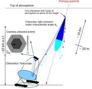
items relevant to the FADC system are presented in this setion. Figure 1
shows the working priniple of an air Cherenkov telesope. A high energy
gammarayentering theearth'satmosphereinitiatesashowerasade of ele-
trons and positrons. These radiateCherenkov light, whih is olleted by the
mirrorandfoussedontothePMTameraoftheMAGICtelesope.Themain
bakgroundoriginatesfrommuhmore frequentshowers indued by isotropi
hadroni osmi rays.
189mm
°
0.6 48
55 62 69 76 83 90 96 103 110 117 124 131 138 145 152 159
S [au]
Signal (raw) Mean 103.7 RMS 30.17
189mm°
0.6 48
55 62 69 76 83 90 96 103 110 117 124 131 138 145 152 159
S [au]
Signal (raw) Mean 103.7 RMS 30.17
189mm°
0.6 48
55 62 69 76 83 90 96 103 110 117 124 131 138 145 152 159
S [au]
Signal (raw) Mean 103.7 RMS 30.17
189mm°
0.6 48
55 62 69 76 83 90 96 103 110 117 124 131 138 145 152 159
S [au]
189mm°
0.6 48
55 62 69 76 83 90 96 103 110 117 124 131 138 145 152 159
S [au]
θ
CTop of atmosphere
under characteristic angle Cherenkov light emission
First interaction with nuclei ofPrimary particle
~ 20 m
~10 km a.s.l.
~ 10 km Camera (cleaned event)
Cherenkov Telescope
atmosphere at about 20 km height
Fig. 1.IACT priniple: A osmi high energy gamma ray penetrates in the earth's
atmosphereand initiatesa shower asade of eletrons andpositrons, whih radiate
Cherenkov light. This light is olleted and foussed onto the amera, providing an
image of the air shower. Pituretaken from [5℄.
gamma and hadron indued shower images as well as for images of single
muons. The timing information is therefore expeted to improve the separa-
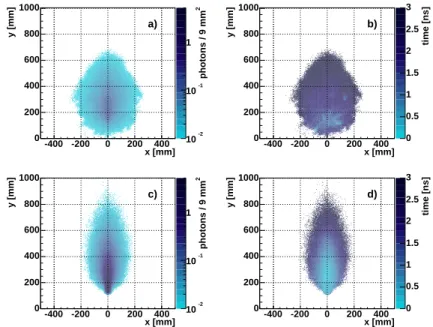
tion of gamma events from the bakground events [6℄. Figure 2 shows the
mean amplitude (a,) and time (b, d) proles for gamma (, d) and hadron
(a, b) indued air showers images on the amera plane of the MAGIC tele-
sope.The impat parameter isxed to120 m and the initialgammaenergy
isset to100 GeV,while the protonenergy isset to200 GeV.The prolesare
obtained by averaging over many simulated showers [7℄. Although the total
shower duration of gamma and hadron indued air showers is omparable,
the photon arrival time varies smoothlyover the gamma shower image while
hadronshower imagesare struturedintime.Thetime strutureofthe image
an alsoprovide essential informationabout head and tailof the shower.
2
photons / 9 mm
10
-210
-11
x [mm]
-400 -200 0 200 400
y [mm]
0 200 400 600 800 1000
a)
time [ns]
0 0.5 1 1.5 2 2.5 3
x [mm]
-400 -200 0 200 400
y [mm]
0 200 400 600 800 1000
b)
2
photons / 9 mm
10
-210
-11
x [mm]
-400 -200 0 200 400
y [mm]
0 200 400 600 800 1000
c)
time [ns]
0 0.5 1 1.5 2 2.5 3
x [mm]
-400 -200 0 200 400
y [mm]
0 200 400 600 800 1000
d)
Fig.2.Mean amplitude (a,) andtime (b, d)prolesfor gamma(, d) andhadron
(a, b) indued air showers images on the MAGIC amera plane from MC simula-
tions.Theimpatparameterisxedto120mandtheinitialenergy ofthegammais
setto100GeV, whiletheprotonenergy issetto200GeV. Theproles areobtained
by averaging over many simulated showers [7℄. The timing struture of the image
an provide viable information about the headand the tail of the shower as well as
help to disriminate between gamma and hadron indued showers.
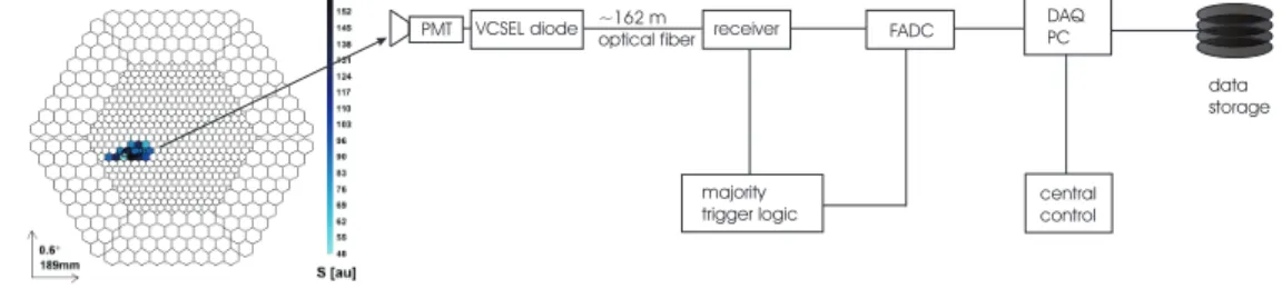
The MAGIC read-out hain, inluding the PMT amera, the analog-optial
link, the majority trigger logi and FADCs, is shematially shown in gure
3.Theresponseof thePMTs tosub-ns inputlightshows apulseof FWHMof
1.0 - 1.2ns and rise and fall times of 600 and 700 ps orrespondingly [8℄. By
modulatingvertialavitysurfaeemittinglaser(VCSEL)diodesinamplitude
the ultra-fastanalogue signalsfromthe PMTs are transferred via 162m long,
multimode graded index 50/125 m diameter optial bers to the ounting
house[9℄.Aftertransformingthe lightbaktoaneletrialsignal,theoriginal
VCSEL diode receiver FADC
central control
~162 m optical fiber
data storage DAQ
PMT PC
majority trigger logic
Fig. 3. Current MAGIC read-out sheme: the analog PMT signals are transferred
via an analog optial link tothe ounting house where after the trigger deisionthe
signalsaredigitized byusinga 300MHzFADCssystemandwrittentothehard disk
of a DAQPC.
In order to sample this pulse shape with the present 300 MSamples/s FADC
system,thepulseisstrethedtoaFWHMof>6ns(theoriginalpulseisfolded
with a strething funtion of about 6ns). This implies a longer integration
of LONS and thus the performane of the telesope on the analysis level is
degraded.
BeausetheurrentMAGICFADCshavearesolutionof8bitonly,thesignals
are split intotwo branhes with a fator of 10 dierene ingain. One branh
isdelayed by 55nsandthen bothbranhesare multiplexedand onseutively
read out by one FADC. The FADC system an be read out with a maximum
sustained rateof1kHz. A512kbytesFIFOmemoryallows short-timetrigger
rates of up to 50kHz.
3 The Ultra-fast Fiber-Opti MUX-FADC Data Aquisition Sys-
tem
TheMAGICollaborationisgoingtoimprovetheperformaneofitstelesope
by installinga fast (2GSamples/s) FADC system, whih fully exploits the
intrinsi time strutures of the Cherenkov light pulses. The requirements for
suha system are the following:
10bitresolution at a2 GSamples/s samplingrate
500 MHzbandwidth of the eletronishain inludingthe FADC
up to1 kHz sustained event triggerrate
deadtime 5%.
It is interesting to note that in experiments where FADCs are used to read
out a multihannel detetor in the ommon event trigger mode, only a tiny
fration of the FADC memory depth is oupied by the signal while the rest
iseetively \empty"[11,12℄. One antry toorretthis\ineÆieny ofuse"
by \paking" the signals of many hannels sequentially in time into a single
FADC hannel,i.e. by multiplexing.
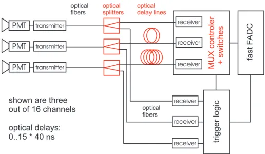
Following this simple idea, a multiplexing system with ber-opti delays has
beendevelopedfortheMAGICtelesope.Theblokdiagramisshowningure
4.The ultrafastber-opti multiplexeronsists of three main omponents:
ber-optidelays and splitters
multiplexereletronis: fast swithes and ontrollers
ultra-fastFADCs.
fastF ADC
PMT PMT PMT
receiver receiver receiver transmitter
transmitter transmitter
receiver receiver
MUXcontroler +switches triggerlogic
receiver optical
splitters
optical delay lines
optical fibers optical
fibers
shown are three out of 16 channels optical delays:
0..15 * 40 ns
Fig. 4. Shemati diagram of the multiplexed ber-opti ultra-fast FADC read-out.
Part of the analog signal that arrives via the ber-optilink from the PMTamera
isbranhed o and fed into amajority trigger logi. Theother partof the signalsis
onseutively delayed in optial bers. Channels are onneted onseutively one by
one to the ultra-fast FADC, using fast swithes. Thereby the noise from the other
hannels iseÆiently bloked.
AftertheanalogoptiallinkbetweentheMAGICPMTameraandtheount-
inghousetheoptialsignalsaresplitintotwoparts.Onepartofthesplitsignal
isused asaninputto thetriggerlogi.The otherpart isusedfor FADC mea-
surements after passing through a ber-opti delay line of a hannel-spei
length.
Themultiplexereletronisoperatesinthefollowingway:Theommontrigger
theanalogsignaltopassthroughand bedigitizedbythe FADC.Allthe other
swithesarelosedduringthistime.Whenthedigitizationwindowfortherst
hannelis overthe orresponding swith islosed.The losed swith strongly
attenuates the signal transmission by more than 60 dB for the fast MAGIC
signals. Then the swith number two is opened suh that the aordingly
delayed analog signal from the seond hannel is digitized and so forth, one
hannel at a time until the last one is measured. In this way one \paks"
signalsfromdierenthannels inatime sequene whih an bedigitizedby a
single FADC hannel.
Beause of the nite rise and fall times of the gate signals for the swithes
and beause of some pik-up noise fromthe swith one has toallow for some
swithing time between the digitizationoftwoonseutive hannels. Thegat-
ingtimefor eahhannel wasset to40ns, ofwhihthe rst and last5nsare
aeted by the swithing proess.
For the use in MAGIC a 16! 1 multiplexing ratio was hosen. 16 hannels
are read out by a single ultra-fast FADC hannel. The hosen multiplexing
ratio isa ompromise between
Deadtime:the digitizationofoneevent takes16*40ns=640ns. Duringthis
timenoothereventan be reorded.Compared tothe maximumsustained
triggerrate of up to 1 kHz this dead time isnegligible.
Noise due to ross-talk through the losed swithes: The attenuated noise
ofthe otherhannelsould inuene the ativesignal hannel.
Cost of the FADCs
Mehanial onstraints,e.g. board size, length of wires and bers.
3.2 Optial Delaysand Splitters
Optial bers were hosen for the analog signal transmission between the
PMT ameraand the ounting house beause they are lightweight,ompat,
immunetoeletro-magnetipik-upnoiseandprovidenopulsedispersionand
attenuation[9℄.Thesignalattenuationat1kmberlengthisabout2.3dBfor
thehosen850nm wavelengthofthe VCSELs.Theanalogsignaltransmission
oersa dynami range largerthan 60 dB.
Using ber-opti delays ultra-fast analog signals an be delayed by several
hundreds of ns. Thus a large number of suessively delayed signals an be
multiplexed and read out by a single hannel FADC. Part of the analog sig-
nal has to be split o before the delay lines for trigger. Therefore ber-opti
splittersof type 1!2 are used.
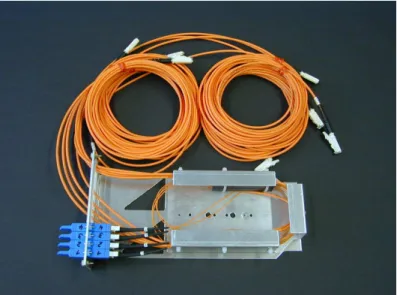
length,orrespondingtoadelayof710nsand750ns.Figure6showsamodule
offourgradedindex(GRIN)-typeber-optisplitterswith50:50splittingratio
(for a tehnial desription see [13℄). The modules have standardized outer
dimensions and an be assembled in 3U hight 19" rates. The splitters and
optialdelaylinesare ommeriallyavailablefromthe ompany Sahsenkabel
[14℄.
Fig.5.Twohannelber-optidelaymoduleof 142and150mlength,orresponding
to a delay of 710 and 750 ns, respetively. Mehanial dimensions: 235 mm * 130
mm(3U) * 35 mm (7HP).
Fig.6.Fourhannelber-optisplittermodule,GRINtehnology and50:50splitting
ratio. Theouter dimensions are:235 mm * 130 mm (3U) * 35mm (7HP).
Themultiplexereletronisonsistoffourstages.Therststageisaberopti
reeiver, where the signals from the optial delay lines are onverted bak to
eletrial pulses using PIN diodes. In a seond stage, part of the eletrial
signal is branhed o and transferred to a monitor output. The third stage
onsists of ultra-fast swithes whih are ativated one at a time. In the last
stage all 16 hannels are summed to one output. The multiplexed signals
are then transferred via 50 oaxial ables to the FADC hannels. Table 1
summarizes the speiations of the multiplexer eletronis.
Table 1
Speiations of the eletronis for analogsignal multiplexing.
Mehanialsize 370 mm (9 U)* 220 mm* 30 mm (6 HP)
Numberof hannels 16
Analog input via 50/125 mgradedindexber, E2000onnetor
Gain 25, inludingthe VCSEL transmitter
Dynamirange max output amplitude:1V
Power supplies +12 V,5V
Power dissipation 20 W
Trigger input LVDS
One multiplexer module onsists of one 6 layer motherboard and 16 double
layer swithboards, whih are plugged into the motherboard via multiple pin
onnetors. Figure 7 shows a photo of the printed iruit MUX motherboard
with 16mounted daughter swithboards.
The motherboard inludes the following omponents:
16opto-eletrialonverters
16monitoroutputs
the DigitalSwith Controliruit (DSC)
the triggerinput toativate the DSC
16ultra-fast swithes on16swithboards
the 16hannel summingstage.
One opto-eletrial onverter onsists of a reeptale, a PIN photo diode,
paked in the E2000-onnetor. The photodiode is biased by 12 V to redue
its intrinsi apaity for speed and noise optimization. The urrent signal
of the PIN photo diode is onverted into an equivalent voltage signal by a
transimpedane-amplier. Its amplier-IC has a gain-bandwidth produt of
about 1.5 GHz and a very high slew rate of about 4000 V/s. The trans-
impedaneis1000.Amonitoroutputonsistsofanultra-wideband(UWB)-
driver-amplier,whihtransmitsthe signalfrom thetransimpedane-stage to
ofa triggerinput,16opto-eletri onverters, 16monitor signaloutputs,theDigital
Swith Control iruit (DSC), 16 daughter swith boards and two summing stages.
Theoverall size is 370 mm(9 U) * 220 mm * 30mm (6 HP).
a50 -SMA-onnetor.
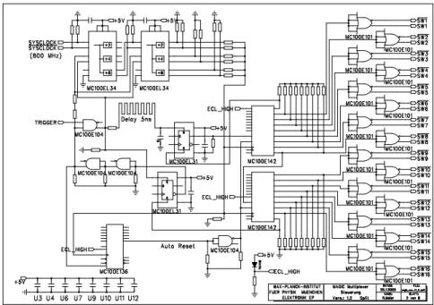
Fig. 8. Ciruit diagram of the Digital Swith Control iruit (DSC): The trigger
initiates a sequeneof 16 PECL high levelsof 40ns duration applied onseutively
tothe swith boards.
Figure8showsthe iruitdiagramoftheDigitalSwithControliruit,DSC.
It onsists of the following parts:
50MHz to800 MHz and works inPECL mode. It is rystal stabilizedand
set to800 MHz.
A digital delay line (DDL) that an be set from 2 ns to 10 ns with 11 bit
auray.It an beused toadjustthe trigger timesbetween dierentMUX
motherboards.
Adigitallok-in-iruit(DLC)synhronizes the MUX-sequenetothetrig-
ger signal.The lok-in jitteris 1.25 ns(=1=[800MHz℄).
16dierentialPECL-driversthattransmittheMUX-sequenesignalstothe
orrespondingswithboards.
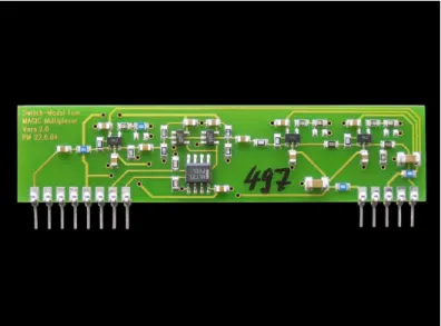
Eahswithboard inludestwo ultra-wideband (UWB)-amplieriruits, fol-
lowed bytwons-swithingMOSFETs operatedinseriesandoneUWB-driver-
amplier-iruit. MOSFET swithes were hosen due to their fast swithing
propertiesand averyfast stabilizationof the signalbaselineafterthe swith-
ing. The smallross-talk through the losed swith is further redued by the
serial operation of two swithes. An on-board PECL to CMOS onverter
distributes the digital swith-ontrol-iruit (DSC)-signal to the MOSFET-
swithes in parallel. Figure 9 shows a photo of the swith board, while its
iruit diagramisshown ingure 10.
Fig. 9. The printed iruit board for fast swithing. The swith board ontains two
ns-MOSFET-swithes operated in series. Its mehanial dimensions are 80 mm *
20mm *5 mm.
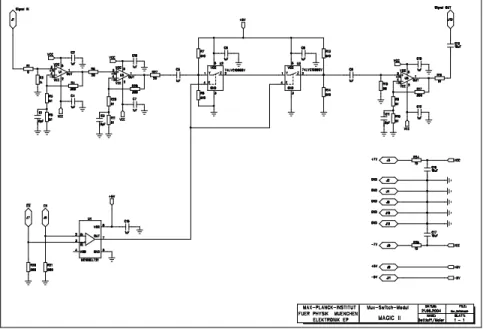
In a passive summation, the swith parasiti apaitanes would add up and
an signiantlywiden the signalpulse. Toavoid this,a two-step ativesum-
mationwashosen:In therst step,the outputsoffourhannelsaresummed
together. In the seondstep, the fourresulting outputsare summedintoone.
ForthesummingUWB-ampliersareused.Thetwo-stepsetupkeepsthehan-
nelwiresshort, andpermitstouse the ampliersinthe faster invertingmode
whilekeepingthe signalpolaritynon-inverting.Finally,anUWB-driversends
Control iruitopens both of the ns-MOSFETswithes operated in series.
the multiplexed signals over a 50 -SMA-oaxial onnetion to the FADC.
The iruit diagramof the summation stage is shown ingure 11.
Fig. 11. Shematis of the two-step summing stage of the multiplexed signals. The
two-step setup keepsthe hannel-wires short and allows touse the UWB-ampliers
in the faster inverting mode while keepingthe signal polarity non-inverting.