653 Improving the SO2 and HCl Removal Efficiency by 30 % in Existing Dry FGC
Flue Gas Treatment
Improving the SO
2and HCl Removal Efficiency by 30 % in Existing Dry FGC without any Capital Investment
– On-Site Observations and Results on Latest Developments –
Stéphane Crevecoeur and Razvan Tuliga
1. Evolution of waste-to-energy plants ...653 2. Description of the tests and results collected ...655 2.1. Description of the sorbent used for this evaluation –
Evolution of the lime-based sorbent ...655 2.2. Trial procedure ...659 2.3. Trial results ...660 2.3.1. Modification of hydrated lime specification in dry flue gas cleaning ....660 2.3.2. Modification of hydrated lime specification in dry flue gas cleaning ...660 3. Conclusions ...661 4. Sources ...662 Dry sorbent injection (DSI) techniques are well known and have been used for a long time in flue gas cleaning systems to control emissions in combustion boilers, coal boi- lers, biomass firing and energy from waste plants. In this type of systems, a powdered sorbent is injected pneumatically directly in the upper part of the furnace or in the flue gas ducts before a dedusting unit. Several pollutants can be removed using this simple technique but the DSI’s removal efficiency is a function of many parameters, like flue gas composition, flue gas temperature, type of equipment and type of sorbent used.
This paper presents the latest product improvement and process optimization that Carmeuse has achieved and the associated Flue Gas Cleaning results obtained with different hydrated lime qualities for flue gas cleaning. We will show how some of the process parameters will influence the flue gas cleaning process and how efficiency improvements of more than 30 % can be achieved by optimizing the sorbent and the operation of the flue gas cleaning unit.
1. Evolution of waste-to-energy plants
In order for the energy recovery from waste installations to prevent the acidic pollutants to disseminate in the environment, they require advanced technology solutions (referred as the Best Available Techniques) and chemical reagents to neutralize acid pollutants and comply with the increasingly restrictive permitted emission limits.
Stéphane Crevecoeur, Razvan Tuliga
654
Flue Gas Treatment
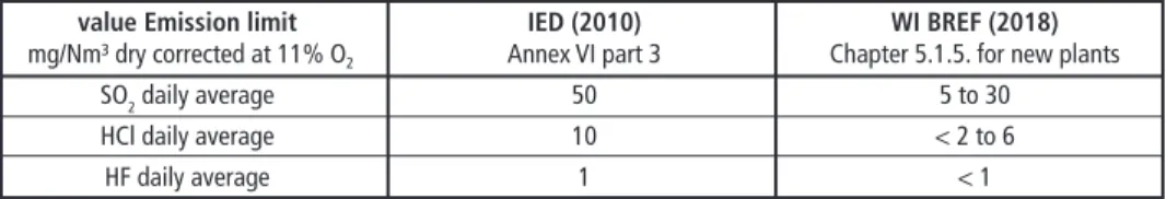
The process of incineration of municipal and commercial waste generates flue gases containing pollutants such as nitrogen oxides, particulate matter, acid gases (mainly hy- drochloric acid, sulphur oxides and hydrofluoric acid) and numerous micro-pollutants, such as volatile heavy metals (Cd, Pb, Hg…) and organic compounds (e.g. dioxins and furans) [5, 19, 20]. The acid gases [17] are one of the main components which require cleaning treatments, but as well as removal efficiencies so high that almost a complete elimination of these pollutants from the flue gases is required in order to respect reg- ulatory limits to stack emissions fixed by competent authorities under the Industrial Emission Directive frame for European Union [10]. The evolution of the limits un- derlines for operators a need to increase the removal efficiencies of those pollutants at each revision of the legislation. This can be visible in Table 1 when comparing the IED document [10] with the newest emission limit values included in the recently released Final Draft of the Waste Incineration BREF document [11].
Table 1: Evolution of the emission limit value for waste incineration between Industrial Emission Directive (IED) and latest Waste Incineration (WI) Best Available Technique reference (BREF) document
value Emission limit IED (2010) WI BREF (2018)
mg/Nm³ dry corrected at 11% O2 Annex VI part 3 Chapter 5.1.5. for new plants
SO2 daily average 50 5 to 30
HCl daily average 10 < 2 to 6
HF daily average 1 < 1
Recently, due to the reducing waste volume and the increasing of separate waste collec- tion [14, 21], several WtE plants have suffered a decrease of available residual municipal waste. The operators substituted their missing urban waste with an increased ratio of commercial wastes, frequently more contaminated by chlorine (Cl), sulphur (S), and/or fluorine (F) [1, 13, 18]. These elements originate more hydrochloric acid (HCl), sulphur dioxide (SO2) and hydrofluoric acid (HF) during thermal oxidation, increasing the flue gas cleaning needs (in removal efficiency but as well in process flexibility).
Meeting emission limit value thanks to dry sorbent injection
Dry Sorbent Injection is a post-combustion flue gas cleaning technology where a reac- tive sorbent is injected into the upper part of the furnace (high temperature) or in the duct downstream the boiler (low temperature) to react directly with the products of combustion. The technology effectively and economically mitigates potential emission problems in the flue gases. Dry Sorbent Injection advantages include lower equipment costs (first cost) as well as decreases in operations and maintenance costs – and have a lower life-cycle cost than other technologies [9, 16]. Commonly used sorbents in Dry Sorbent Injection systems include:
• Calcium hydroxide to mitigate HCl, HF, SO2, SO3 and Se,
• Sodium bicarbonate to capture HCl, SO2, SO3 and to some extent HF,
• powdered activated carbon to adsorb heavy metals and organics compounds.
655 Improving the SO2 and HCl Removal Efficiency by 30 % in Existing Dry FGC
Flue Gas Treatment
Reaction products are collected in a downstream particulate control device together with the fly ashes and unreacted sorbent. In function of the sorbent used, these products can be used as feedstock to cement plants or for stabilization of earthen structures. Be- cause a separate scrubber vessel is not needed and no water is involved, capital costs are minimized. Low Capex and operational costs may be partially offset by higher reagent consumption rates due to lower pollutant removal efficiencies when compared to other flue gas cleaning processes, because historically the DSI processes used to show lower removal efficiencies. This higher reagent consumption rate pushed both engineering companies that supply the installations as well as companies supplying the reagents to develop systems and products that increase the effectiveness of the reaction by optimizing the reaction conditions (engineering companies) and designing dedicated sorbents (reagent suppliers).
Among the systems used to improve the efficiency we can find by-product recirculation, by-product reactivation, reaction towers, flue gas conditioning, etc. all of which look towards improving the conditions of the flue gases and improving the contact time between the sorbent and the pollutants in order to increase the speed of the reaction, and overall to improve the utilization rate.
The reagent suppliers are also trying to increase the speed of the reaction and the utilization rate by designing and producing engineered products, which at the same time can also bring more flexibility in regards to the process conditions required for the reaction.
Overall, all the developments done towards improving this type of systems have man- aged to increase the removal efficiencies that can be obtained, from an initial historical 50 to 70 % up to more than 90 % with the latest technologies.
2. Description of the tests and results collected 2.1. Description of the sorbent used for this evaluation –
Evolution of the lime-based sorbent
Over the last decade, hydrated lime manufacturers have developed more efficient sor- bents to meet the increased removal efficiencies needed on the market. One of them, Carmeuse developed the CleanCalco product range that will be used for this comparison.
The product range, together with the on-site support given by their expert team, brings flexibility to the end-user by enabling him to optimize the flue gas cleaning process with minimal or, in some cases, without any required CAPEX.
The products available in this product range include standard calcium hydroxide sorbents (Ca(OH)2) and optimized sorbents. This dedicated calcium hydroxide offer different physical properties regarding specific surface area and porous volume, which fit to every need encountered in the dry flue gas cleaning process. Several papers [8, 15] already documented the influence of these parameters under some flue gas conditions. Such porosimetric examination is done by means of a gas sorption analyser using nitrogen
Stéphane Crevecoeur, Razvan Tuliga
656
Flue Gas Treatment
view field: 9.048 ~µm det: SE detector name: 11-1404-2
2 µm
physisorption and desorption isotherms at -196 °C in order to measure the specific sur- face area according to the multipoint BET method [6] and the pore volume according to the BJH method [2].
The product range also included specially engineered sorbents like the CleanCalco De- purcal, initially developed and tested in 2011 in several Italian waste-to-energy plants.
Its particularity is to be injected directly in the boiler at temperatures above 900 °C. The product underwent several stages of improvement that increased its efficiency, and more importantly, its efficiency in SOx absorption rates, improvements that were proven with the help of several on-site trials in 2013 and 2014.
These improvement processes brought the following advantages [3, 4, 7, 12]:
• neutralizes the acid gases (SO2, SO3, HF and HCl) directly in the furnace/boiler;
• optimizes the performance of the flue gas cleaning process, with less reagent injected and less by-product generation;
• raises the melting point of the ash, making them porous, light and friable; and
• reduces the fouling of the tube and facilitates cleaning.
On top of that, as the product is used in combination with a downstream flue gas clean- ing installation, it reduces the amount of sorbent used and the variability of the acid pollutants needed to be treated downstream. Flue gas cleaning overall efficiency and compliance cost for operators can thus be reached by:
• the direct injection in the boiler of the CleanCalco Depurcal that can offer the full advantages presented above, combined with
• the downstream effectiveness of an optimized sorbent like CleanCalco HPV.
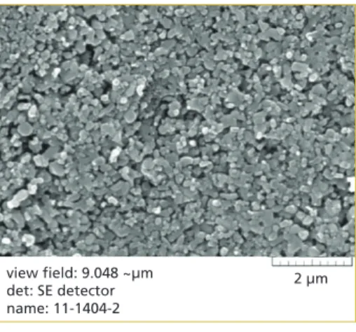
Figure 1: Scanning Electron Microscopy of CleanCalco Depurcal activated at 1,000 °C
The injection in the boiler itself is needed to have the thermal activation of the prod- uct. In Figure 1, we can see a sample after being thermally activated at 1,000 °C. This illustrates perfectly the micro-porosity cre- ated on the particle surface transforming the grain into a highly reactive sorbent that mitigates acid pollutants. In the dif- ferent tests mentioned below, we injected our new sorbent in a temperature range between 850 °C and 1,000 °C. Due to the proven high efficiency of the product, its injection in the furnace at high tempera- ture is now considered a BAT in the latest Waste Incineration BREF [11].
CleanCalco HPV is a premium hydrated lime sorbent, optimized for the use in end-of- pipe Dry Sorbent Injection processes. It presents a higher SO2 specific capture thanks to the higher porosity and higher specific surface. The result is illustrated in Figure 2: a similar dosage increases the capture, or a similar capture is reached with a lower injection.
Dorfstraße 51 D-16816 Nietwerder-Neuruppin Phone: +49.3391-45.45-0 • Fax +49.3391-45.45-10 E-Mail: order@vivis.de TK Verlag GmbH
order now www. .de
Air Pollutant Emissions and their Control
– with the focus on waste incineration facilities –
This comprehensive text and practical handbook thoroughly presents the control of air pollutant emissions from combustion processes focusing on waste incinerators. Special characteristics are emphasised and the differences to emission control from combustion processes with other fuels are explained.
The author illustrates the origin and effects of air pollutants from incineration processes, the mechanics of their appearance in the incineration process, primary and secondary measures for their reduction, processes of measuring the emissions as well as the methods of disposing the residues. In particular, the pros and cons of procedual steps and their appropriate combination under various conditions are emphasised.
Moreover, the book contains information and analyses of the emissions situation, the consumption of operating materials and of backlog quantities as well as of the cost structure of waste incinerators with regard to their applied control system.
Furthermore, the author explicates the contemporary legal, scientific and technological developments and their influence on air pollutant emission control. An evaluation of the status quo of air pollutant control at waste incinerators in Germany, practical examples about possible combinations and typical performance data complete the content.
Accordingly, this book is a guideline for planing a reasonable overall concept of an air pollutant control that takes the location and the segregation tasks into consideration. This book is addressed to students, decision makers, planners and the operating practicioners if for example the construction of a new system or the implementation of improvement measures have to be conducted.
published: 2017 120.00 EUR published 2014
50.00 EUR
Available in German and English!
revised versio n
Emissions and Emission Monitoring
340 Fixed mirror
Focussing mirror Beam splitter
with compensator
Moving mirror
Light source Gas sample Gas sample Collimator
Detector Sample cell
Figure 242: Measurement principle of an FTIR multi-component spectrometer with a Michelson interferometer setup
Source:
TÜV Süd Industrie Service GmbH, UBA-Texte 05/08, adapted
splitter where they are brought together to interfere with each another in intensity as they recombine. Depending on the mirror displacement, the interference may be constructive (increasing) or destructive (decreasing). When using polychromatic light, the interference occurs for each wave length so that the interference intensities of the individual wave lengths superpose one another [369].
of the target component and are directed by a focusing mirror to an infrared detector is computed from the recorded interferogram (intensity at detector as a function of mirror displacement) by mathematical Fourier transformation. For quantitative eva- luation, the calculated infrared spectrum is compared with a reference spectrum [380].
An alternative to the Michelson interferometer is the vibration-insensitive RockSolid arrangement [356].
341 9.2.3.3.2 Multi-component measurement by non-dispersive infrared spectroscopy Non-dispersive infrared (NDIR) spectroscopy is based on the absorption of an in- frared spectrum wavelength that is unique to the gaseous component to be detected.
In contrast with dispersive infrared spectroscopy, non-dispersive methods do not spectroscopy is applicable to multi-component analysis, i.e. the simultaneous analysis of several emission parameters, and is frequently also used for raw gas measurements.
detector Light source Sample cell Calibration filter
Lens Detector
Filter wheels Chopper
Figure 243: Measurement principle of a multi-component NDIR spectrometer with heated sample gas cell Source: Boneß, M.: Messsysteme und Analysatoren zur kontinuierlichen Prozesskontrolle und Emissionsüberwachung in und Betrieb von Anlagen, Vol. 1, pp. 527–538. Neuruppin: TK Verlag, 2010 As infrared detectors can only detect changes in the infrared radiation, they require a modulated (pulsed) infrared source that is temporarily interrupted by a mechanical
component and selects the spectral region of its absorption band. If several gas com- ponents are to be analysed, chopper wheels covering several infrared spectral regions to calculate the gas concentration, which requires a concentration-independent refer- ence signal for comparison. For this purpose, NDIR analysers may be equipped with absorption band of the analysed component (bi-frequency technique). Alternatively,
.
Continuous Emission Monitoring
hardcover with coloured illustrations AirPollutantEmissions_engl.pdf 1 12.09.18 13:10
POLLRICH GmbH
Phone: +49 (0)271 66123-0 . info@pollrich.com . www.pollrich.com
INDUSTRIAL FANS FOR WASTE INCINERATION PLANTS
Expert knowledge with discharging of toxic and explosive gas mixtures
Heavy-duty industrial standards
With longstanding experience in manifold waste incineration plants all over the world, we offer state-of-the-art recirculation fans, combustion air fans, ID-fans and primary- and secondary air fans, combined with an extensive and reliable service.
Tailor-made centrifugal fans for the roughest conditions
Reliable fan service, 24/7 worldwide
POLLRICH QUALITY:
659 Improving the SO2 and HCl Removal Efficiency by 30 % in Existing Dry FGC
Flue Gas Treatment
2.2. Trial procedure
Each on-site trial is preceded by a preliminary study done by a team of experts. It aims at understanding the fundamental characteristics of the installations from each plant, which in turn enables them to find, together with the operator of the plant, the best hydrated lime product to be injected, the optimum injection point, and the KPI’s that will be followed during the trial itself.
Figure 2: Impact of Ca(OH)2 specifications (standard product vs. CleanCalco HPV) on the removal efficiency in function of the Ca(OH)2 dosage
Table 2: Ca(OH)2 specifications for standard hydrated lime and CleanCalco HPV
CleanCalco HPV Standard Calcium hydroxide
Ca(OH)2 available above 92 % 70 to 90 %
specific surface (BET) above 40 m²/g 15 to 18 m²/g
porous volume (BJH) about 0,20 cm³/g below 0,10 cm³/g
The sorbent has a higher porosity and a higher specific surface (as mentioned in the Table 2 below), that offer an increased contact area between the flue gases con- taining SO2 and the neutralizing agent, Ca(OH)2.
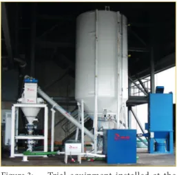
After this first preliminary study, it is also decided together with the operator if a dedicated trial equipment will be used or not. If it is used, the injection flange is in- stalled at the decided injection point and a dosing equipment is installed on-site, as seen in Figure 3.
With the help of the installed equipment, the trial can start. The team is present on site in order to handle the process optimi- zation by using several fixed or variable dosing rates in order to see which is the optimum consumption required in each particular case.
Figure 3: Trial equipment installed at the trial location to run temporary dry sorbent injection
lime dosage pollutant removal efficiency
%
dosage reduction
efficiency improvement
CleanCalco HPV standard hydrated lime
Stéphane Crevecoeur, Razvan Tuliga
660
Flue Gas Treatment
2.3. Trial results
2.3.1. Modification of hydrated lime specification in dry flue gas cleaning
Case: Municipal solid waste incineration plant with a total 63,000 t waste/year capacity on two lines
The specification of the sorbent used in dry systems has a big impact over the efficiency of the system itself. In this case, the FGC system consists of a silo, a dosing screw and a pneumatic transport of the sorbent to the injection point located before a bag filter.
0 20 40 60 80 100
percentage
%
dosing rate
SO2 emission
HCI emission reference period CleanCalco HPV
lower24 % SO2
emission
The pollutants measured at the stack were HCl and SO2, and the system was automatically controlling the dosing rate of the sorbent based on the emission level at the stack. In order to identify quickly the benefit of using CleanCalco HPV in the installation it was decided together with the operator to use a trial equipment and to try to inject a similar amount of sorbent as they are normally using. The reference product was as well a premium hydrate with high specific surface (BET = 40 m²/g) and porosity (0.20 cm³/g) but with a different pore size distribution.
As it can be seen in Figure 4 by switching to this sorbent, the plant managed to achieve 24 % lower SO2 emissions at the stack, while maintaining the same dosing Figure 4: Trial results: 24 % lower SOx emis-
sions at the stack when using Clean- Calco HPV instead of alternative Calcium hydroxide offering high porosity and high specific surface area with similar dosage
rates and the same HCl emission levels. This means that for the same amount of Ca present in the system, a higher utilization rate was achieved. These lower SO2 emissions also ensure the future compliance of the plant.
2.3.2. Modification of hydrated lime specification in dry flue gas cleaning
Case: Municipal solid waste incineration plant with a total 700,000 t waste/year capacity on four lines
In this case, the flue gas cleaning process consists in a dry process with a con- ditioning tower but without a recirculation of the material collected in the fil- ter. The trial intended to demonstrate the impact and the improvement brought by the use of a more performing hydrated lime vs. the reference case operating with hydrated lime with high specific surface (BET = 40 m²/g) and high porosity (0,2 cm³/g). CleanCalco HPV hydrated lime offers an improved specific surface area
661 Improving the SO2 and HCl Removal Efficiency by 30 % in Existing Dry FGC
Flue Gas Treatment
of above 40 m²/g as well as a porous volume of about 0.20 cm3/g with engineered pore size distribution to improve sulphur capture. In this case, the product was used directly from the installation in the plant.
In Figure 5, the orange column corresponds to the reference case normalized at 100 % dosing rate, while the dark blue column corresponds to the full operation with the optimized sorbent. As it can be seen, there is a decrease of approximately 17 % in the dosing rate of the sorbent when the switch to the optimized product was done.
0 10 20 30 40 50 60 70 80 90 100 percentage
%
reference period
CleanCalco HPV
CleanCalco HPV optimized dosing
This decrease corresponds to the same emission levels at the stack, as the process automation system of the customer was controlling the dosing rate of the sorbent automatically, based on the removal re- quirements of the pollutants.
During the trial the technical expert team also noticed that the stability of the sorbent dosing rate as well as the pollutant levels at the stack were very low, and had quite big and unexplained variations. At that moment, they moved together with the customer in making a more in detail root cause analysis in order to see what was causing the issue with the dosing of the sorbent. After identifying the cause as a setting in the operation of the dosing screw, they corrected the fault and man- aged to decrease further the consumption Figure 5: Trial results: up to 31 % dosage
reduction (for same stack emission) when using CleanCalco HPV in an optimized dosing system instead of alternative Calcium hydroxide offering high porosity and high specific surface area
rates with an extra 14 %, reaching a total decrease of 31 % in the sorbent consumption rates by simple flue gas cleaning process optimization with a correct sorbent and a correct dosing loop.
3. Conclusions
CleanCalco HPV injection at the cold end DSI is an innovative answer to the flue gas cleaning concerns both in waste-to-energy plants as well as in other applications. This solution allows the users to achieve their required emission limit values while at the same time reducing their costs and increasing their installations efficiency while at the same time reducing the quantity of sorbent used by more than 30 %.
The major key implications on operators’ process focus on:
• increasing FGC reliability regarding compliance with emission value limits at the stack,
• generating savings on operational cost linked to flue gas treatment,
• higher flexibility of the FGC process,
Stéphane Crevecoeur, Razvan Tuliga
662
Flue Gas Treatment
• high efficiency on acids removal (HCl, SO2, SO3, HF),
• full time compliance to emission standards imposed at the stack, and
• suitable process for a variety of boiler types/manufacturers.
4. Sources
[1] Astrup T., Riber C., Pedersen A.J.: Incinerator performance: effects of changes in waste input and furnace operation on air emissions and residues. Waste Management & Research 29, 2011, 57-68.
[2] Barrett, E.P., Joyner, L.G., Halenda, P.P.: The determination of pore volume and area distribu- tions in porous substances. I. Computations from nitrogen isotherms. In: Journal of American Chemical Society 73, 1951, 373-380.
[3] Biganzoli L.,Grosso M., Marras R., Racanella G.: Absoption des gaz acides à haute température;
évaluation expérimentalre sur trois installations d’incinération en Italie. Pollutec conference, 2012, Lyon, France.
[4] Biganzoli L.,Grosso M., Marras R.: Assorbimento dei gas acidi ad alta temperatura: valutazioni sperimentali su tre impianti di incenerimento. Ecomondo conference, 2012, Rimini, Italy.
[5] Brereton C.: Municipal solid waste – incineration, air pollution control and ash management.
In: Resources, Conservation and Recycling 16, 1996, 227-264.
[6] Brunauer, S., Emmett, P.H., Teller, E.: Adsorption of gases in multimolecular layers. In: Journal of American Chemical Society 60, 1938, 309-319.
[7] Crevecoeur S., Tuliga R.: Latest results in Direct Alkaline Reagent Injection demonstrating com- pliance cost optimization, higher reliability, ease and comfort of use. PowerGen India conference, 2015, Delhi, India
[8] Dantuluri S.R.: Limitation of sulfur dioxide removal in a FGD Spray Dryer using once through slaked lime. PhD diss., University of Tennessee, 1988. Retrieved 07.2019 from: https://trace.
tennessee.edu/utk_graddiss/1653
[9] EPA-CICA: Fact Sheet – Flue Gas Desulfurization, EPA-452/F-03-034, Retrieved 07.2019 from:
http://www.epa.gov/ttn/catc/dir1/ffdg.pdf>
[10] European Commission: Directive 2010/75/EU of the European Parliament and of the Council of 24 November 2010 on industrial emissions (integrated pollution prevention and control).
[11] European Commission: Best Available Techniques (BAT) Reference Document for Waste In- cineration. Industrial Emissions Directive 2010/75/EU (Integrated Pollution Prevention and Control). Final Draft (December 2018). Retrieved 04.2019 from: http://eippcb.jrc.ec.europa.eu/
reference/BREF/WI/WI_BREF_FD_Black_Watermark.pdf.
[12] Grosso M., Biganzoli L., Giugliano M.: Improving the environmental performances of WTE plants with high temperature flue gas pre-cleaning and enhanced bottom ash recovery. 8th i-CIPEC conference, 2014, HangZhou, China
[13] Komilis D., Evangelou A., Giannakis G., Lymperis C.: Revisiting the elemental composition and the calorific value of the organic fraction of municipal solid wastes. In: Waste Management 32, 2012, 372-381.
[14] Nessi S., Rigamonti L., Grosso M.: Discussion on methods to include prevention activities in waste management LCA. In: The International Journal of Life Cycle Assessment 18, 2013, 1358- 1373.
[15] Rostam-Abadi M., Moran D.L. – Illinois State Geological Survey, Champaign, Illinois, USA;
Roman V.P. – R-C Environmental Services and Technologies, Irvine, California, USA; Yoon H.
and Withum J. A. – Consolidation Coal Company, Library, Pensilvania, USA. High-surface area hydrated lime for SO2 control.
663 Improving the SO2 and HCl Removal Efficiency by 30 % in Existing Dry FGC
Flue Gas Treatment
[16] Sakadjian B.B., Silva A.A., Campobenedetto E.J.: Multi-Pollutant Control Demonstration in a Pilot Plant with Dry Sorbent Injection. Air quality VIII conference, 2011, Arlington, Virginia, USA.
[17] Vehlow J.: Air pollution control systems in WtE units: an overview. In: Waste Management 37, 2015, 58-74.
[18] Viganò F., Consonni S., Grosso M., Rigamonti L.: Material and energy recovery from Automotive Shredded Residues (ASR) via sequential gasification and combustion. Waste Management 30, 2010, 145-153.
[19] Werther J.: Gaseous emissions from waste combustion. In: Journal of Hazardous Materials 144, 2007, 604-613.
[20] Wey M.-J., Ou W.-Y-, Liu Z.-S., Tseng H.-H., Yang W.-Y., Chiang B.-C.: Pollutants in incineration flue gas. In: Journal of Hazardous Materials B82, 2001, 247-262.
[21] Zorpas A.A., Lasaridi K.: Measuring waste prevention. In: Waste Management 33, 2013, 1047- 1056.
Acronyms used in the document and definitions BAT Best Available Technique
BET Specific surface
BREF BAT reference document CAPEX Capital Expenditure DSI Duct Sorbent Injection FGC Flue Gas Cleaning FSI Furnace Sorbent Injection
IED Industrial Emission Directive (2010) OPEX Operating expenditure
PV Porous Volume
SEM Scanning Electron Microscopy WI Waste Incineration
Contact Persons
Stéphane Crevecoeur Carmeuse Europe s.a.
Market Manager Flue Gas Cleaning Marketing
Boulevard de Lauzelle 65 1348 Louvain-la-Neuve BELGIUM
+32 10481641
stephane.crevecoeur@carmeuse.com
Stéphane Crevecoeur, Razvan Tuliga
664
Flue Gas Treatment
Razvan Tuliga
Carmeuse Holding s.r.l
Technical Expert Flue Gas Cleaning
Application Technology EuropeCarierei 127a 500052 Brasov
ROMANIA +40 732820567
razvan.tuliga@carmeuse.ro
Vorwort
4
Bibliografische Information der Deutschen Nationalbibliothek Die Deutsche Nationalbibliothek verzeichnet diese Publikation in der Deutschen Nationalbibliografie; detaillierte bibliografische Daten sind im Internet über http://dnb.dnb.de abrufbar
Thiel, S.; Thomé-Kozmiensky, E.; Winter, F.; Juchelková, D. (Eds.):
Waste Management, Volume 9 – Waste-to-Energy –
ISBN 978-3-944310-48-0 Thomé-Kozmiensky Verlag GmbH
Copyright: Elisabeth Thomé-Kozmiensky, M.Sc., Dr.-Ing. Stephanie Thiel All rights reserved
Publisher: Thomé-Kozmiensky Verlag GmbH • Neuruppin 2019 Editorial office: Dr.-Ing. Stephanie Thiel, Elisabeth Thomé-Kozmiensky, M.Sc.
Layout: Claudia Naumann-Deppe, Janin Burbott-Seidel, Sarah Pietsch, Ginette Teske, Roland Richter, Cordula Müller, Gabi Spiegel Printing: Universal Medien GmbH, Munich
This work is protected by copyright. The rights founded by this, particularly those of translation, reprinting, lecturing, extraction of illustrations and tables, broadcasting, micro- filming or reproduction by other means and storing in a retrieval system, remain reserved, even for exploitation only of excerpts. Reproduction of this work or of part of this work, also in individual cases, is only permissible within the limits of the legal provisions of the copyright law of the Federal Republic of Germany from 9 September 1965 in the currently valid revision. There is a fundamental duty to pay for this. Infringements are subject to the penal provisions of the copyright law.
The repeating of commonly used names, trade names, goods descriptions etc. in this work does not permit, even without specific mention, the assumption that such names are to be considered free under the terms of the law concerning goods descriptions and trade mark protection and can thus be used by anyone.
Should reference be made in this work, directly or indirectly, to laws, regulations or guide- lines, e.g. DIN, VDI, VDE, VGB, or these are quoted from, then the publisher cannot ac- cept any guarantee for correctness, completeness or currency. It is recommended to refer to the complete regulations or guidelines in their currently valid versions if required for ones own work.