An 8-Channels 0.13µm-CMOS Front-End for ATLAS MDT-Detectors
M. De Matteis1, F. Resta1, R. Richter2, H. Kroha2, M. Fras2, Y. Zhao2, V. Danielyan2, S. Abovyan2, A. Baschirotto1
1Physics Department.University of Milano-Bicocca, Italy, 2Max-Planck-Institute for Physics, Munich, Germany marcello.dematteis@unimib.it
Abstract—An 8-channels read-out front-end for LHC ATLAS Muon-Drift-Tubes detectors is presented (8xAFE). The system is composed by the cascade of the analog signal processing Front- End and of the Wilkinson A/D (to perform voltage-to-time conversion for time-over-threshold detection). The sensitivity at the output of the analog signal processing chainis13.8mV/fC, while and the Equivalent-Noise-Charge (ENC) is 0.6fC (~3.38ke), performing <12ns preamplifier rise-time. These performances have been achieved, managing very high detector parasitic capacitance at the front-end input (~60pF). Each channel consumes 11mA from a single 3.3V supply voltage. In 0.13µm CMOS, the total area occupancy is 6.3mm2. Keywords—
ATLAS,Muon-Drift-Tubes, Detector, CMOS Front-End.
I.INTRODUCTION
In the last years integrated circuits (ICs) solutions have been widely used in high-energy physic experiments (HEP), with the main aim to replace the common service electronics (based on very old CMOS processes and/or off-the-shelf components[1][2]), with more efficient scaled-down ICs, able to improve sensitivity/noise/power performance while reducing area and consequently increasing pixels read-out resolution. This automatically leads to have better imaging and understanding of the particles collision phenomena.
The Analog Front-End (AFE) [1], actually used for the Monitored-Drift-Tube (MDT) chambers of the ATLAS experiment at the Large Hadron Collider (LHC) at CERN, is a 0.5µm CMOS design, biased at 3.3V. It performs a front-end charge-to-voltage conversion (by a proper Charge-Sensitive- Preamplifier) followed by the analog signal conditioning (amplification and shaping) and the A/D conversion. It features a sensitivity (i.e. voltage vs. charge conversion ratio) of 8.9mV/fC[1], 15ns nominal Peaking Time Delay (i.e. PTD, the front-end capability to quickly detect charge arrival time) and relatively low-noise enabling 5fC minimum detected charge at 10dB Signal-to-Noise-Ratio (i.e. SNR).
As it is well known, LHC is under an aggressive improving process (defined Phase 2 [2]) to enable higher energy events, and better measurement set-up, while maintaining the present structure that exhibits good robustness. In this scenario, concerning the above MDT system, also the AFE has to be improved in terms of performance, while maintain the same architecture (including the 60pF detector capacitance) that is well established in the full system. This paper present the 8-channels MDT-AFE (8xAFE) resulting from the design improvement in terms of:
lower PTD (to achieve the required resolution in the drift time and distance measurement of the MDT drift tubes);
larger sensitivity and higher SNR at 5fC minimum charge.
The large swing required to adopt a single 3.3V supply voltage that can be sustained only by the 0.35µm High- Voltage (HV) devices. Concerning the other requested signal
processing improvements, they have been achieved with a fully improved 8xAFE design. In this way, the 8xAFE performs 11ns-PTD (w.r.t. the original 15ns), 13.8mV/fC- sensitivity (w.r.t. the original 8.9mV/fC) and 15dB-SNR (w.r.t. the original 10dB). These improved results have been obtained without increasing the power consumption that is strongly fixed by the input noise specifications. This means that the technology scaling has been here exploited for rad- hard, performance robustness improvement, and area reduction (about a factor 2x with 6mm2 die size w.r.t. the original 11.9mm2). This paper is organized as follows. Section II introduces the ATLAS experiment key points for electronics development. Section III presents the CMOS 8xAFE circuital/design choices and Section IV is focused on the experimental results, in terms of operating point and time performance (rise time, noise, etc).
II.THE ATLASEXPERIMENT
The ATLAS experiment at the CERN LHC collider is designed to record collisions from protons on protons (p-p collisions) at center-of-mass energies of up to 14 TeV. In order to determine energy and direction of the secondary particles, emerging from the p-p collisions, a sequence of specialized detectors is used for the detection of charged and neutral particles through a shell-like structure. Fig. 1 shows the MDT read-out simplified scheme. The muons emerge from the primary collision and so they are considered the most penetrating component among the charge particles.
The outer ATLAS shell is reserved for muons detection.
Electrons generated by muons in the gas-filled pressurized MDT tubes are drifting to the central wire of the tube. The time-of-arrival of this ionization at the wire is used to measure the distance of the track from the wire. As the muon usually passes through a large number of drift tubes, the position of the muon track can be reconstructed from a combination of measurements in the tubes along the muon trajectory.
Interesting details about the MDT ATLAS readout electronics are given in [4]. The small charge signals coming from the wires are sent to the ‘mezzanine’ board where the 8xAFE is placed (see Fig. 2 for the single-channel system generic block scheme).
Fig. 1 – Muons Detection Scheme [2].
Fig. 2 – 8xAFE Front-End Generic Block Scheme.
Fig. 3 – 8xAFE Charge-Sensitive-Preamplifier Schematic.
This monolithic 8xAFE senses, shapes and converts the signal coming from the tubes, providing time-domain voltage pulses, whose duty cycle is proportional to the amount of charge at the 8xAFEinput. Then the time signal is sent to an off-chip Time-to-Digital Converter (TDC), which forwards the signal arrival times down the data acquisition chain for recording and track reconstruction.
The small charge signals coming from the wires are sent to the ‘mezzanine’ board where the 8xAFEis placed (see Fig. 2 for the single-channel system generic block scheme). This monolithic 8xAFEsenses, amplifies, filters and converts the signal coming from the tubes, providing time-domain voltage pulses, whose duty cycle is proportional to the amount of charge at the 8xAFEinput. Then the time signal is sent to an off-chip Time-to-Digital Converter (TDC), which forwards the signal arrival times down the data acquisition chain for recording, track reconstruction and further analysis.
III.MDT-ASDCIRCUITAL IMPLEMENTATION
The architecture of a single-channel 8xAFEis shown in Fig. 3[3].The overall system consists of 8 identical channels.
The device has been realized in IBM 0.13µm CMOS technology, selected since it has been characterized for radiation hardness. Each channel input signal is (almost ideal) current pulse signal coming from the detector. It is converted into a voltage signal by the Charge-Sensitive-Preamplifier (CSPreamp). The CSPreamp output voltage is then properly shaped by the cascade of three Differential-Amplification stages (DA1, DA2, DA3) to increase the signal power, and, also, to perform out-of-band noise rejection and anti-aliasing filtering for the following ADC.
The DA4 output signal feeds a Comparator (Discriminator Stage in Fig. 2) that by switching-on allows detecting the charge arrival time. Hence the DA3output signal is the analog input signal for the Wilkinson ADC. The ADC provides a time representation of the input signal, performing a voltage- to-time conversion. A proper Programmable Parameters stage has been also embedded, to set the Discriminator threshold (the minimum charge to be detected) and the phases signal needed for Wilkinson ADC operation. Moreover, LVDS drivers have also been designed to interface the 8xAFEchip with the external components of the “mezzanine” board and
the following TDC chip.Test point for DA3 output voltage consists on an analog buffer able to drive the probe for testing purposes (with –2dB drop and a few ns as additional delay).
A. Charge-Sensitive Preamplifier
The overall system behavior is strongly dependent on the performance of the CSPreamp that must manage a very large detector parasitic capacitance (CD≈60pF).
The CSPreamp is composed by two identical symmetrical paths. A dummy preamp has been used for differential signal processing, and as a consequence the input charge is read from one single path (CSP in Fig. 2). The transistor-level scheme of the CSPreamp is shown in Fig. 3.
While the CSPreamp structure is maintained w.r.t. the previous design, the design parameters have been completely re-designed to improve the performance in terms of the input impedance (<120Ω), noise, and speed of response.
Regarding the input impedance, the CSPreamp is based on a cascode common source amplifier, which guarantees large loop-gain for closed-loop operation, and as consequence a better virtual ground at the input node (required by the large CD). The input impedance is maintained almost constant for all in-band frequencies, since at low frequency, it is fixed by RL(=16kΩ) and RF(=16kΩ), while, at higher frequency, it is regulated by the Feedback Capacitance (CF=680fF) and by the detector capacitance (CD=60pF).
The output signal is read at the M2 drain. The M3-RS-M4 source-follower is used to increase and optimize the output node common-mode voltage, for the following DA1 stage, which has NMOS input transistors (for noise minimization).
Regarding CSPream pnoise and speed of response, both are optimized by suitable input device transconductance (gm1).
In this direction, transistor M1 operates in moderate inversion (Vov≈100mV) with a nominal current of 1.6mA in order to have large gm1=25mA/V, much larger than in previous design.
This improves both noise and speed, thanks to a better redistribution of the power (which remains constant) among the different stages. Larger power is allocated to the CSPreamp input stage, saving power elsewhere (mainly in the DAx chain, and in the bias circuit), where it was not necessary. Such large gm1 value improves the speed-of- response as follows. The CSPreamp transfer function is in first approximation given by:
(1) · ·
····
Since gm1=25mA/V and CF≪CD, the zero is at much higher frequency and can be neglected. Assuming infinite gm1, the dominant pole is given by CF·RF, and the output pulse voltage peak value should be approximately given by QIN/CF≈7mV0-PEAK. In this design gm1 has been fixed at
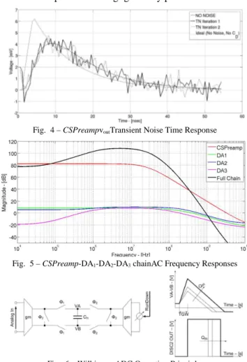
25mA/V, as trade-off between noise and power, resulting in a CSPreamp sensitivity of 1.4mV/fC. These considerations are validated by Fig. 4, where the simulated CSPreamp time response is shown (NO-NOISE curve) and compared with the single-pole ideal system (No-Noise, No-CD curve).
The main effects of the CD capacitance are: lower sensitivity (4mV0-PEAK instead of 6mV0-PEAKfor minimum QIN=5fC) and slightly slower time response (7ns instead of 4ns), w.r.t. the ideal case. The large design gm1 not only avoids significant sensitivity degradation due to the large parasitic CD, but also mitigates the second pole effect, pushing it up to very much higher frequency, hence improving the time performance of the CSPreamp, as shown in eq. (2):
(2) · ·
···· ··
Such large gm1 enforces virtual ground and, then, lowers CSPreamp equivalent input impedance down to ≈60Ω, (nominal, in order to be <120Ω over PVT) acceptable for PTD, and noise. Two transient noise iterations have been run, to highlight the thermal noise contribution, resulting in 0.55mVRMS-in-band output noise power. The SNR at the CSPreamp output is 19dB in case of minimum input charge of 5fC, and it rises up to 45dB at 100fC.
B. DA1-DA2-DA3
The CSPreamp output signal is amplified&filtered by the DA1-DA2-DA3 stages, which shape the signal to convert the pulse into a bipolar shaping and to define the fall-down time.
In this DA1-DA2-DA3 chain, the scaled 0.35µm devices have been exploited in the reduction of the parasitic capacitance, and, then in increasing the speed while reducing power consumption. The frequency response at the output of each stage is plotted in Fig. 5. The full chain exhibits a pass-band characteristic with a 5MHz center frequency. The high-pass part, mainly imposed by DA3, shows a 30kHz corner frequency and a slope of +6dB/octave (1st-order high-pass filter). The low-pass part is the superposition of all 4 amplifier low-pass characteristics that have a bandwidth between a few tens and hundreds MHz.
C. Wilkinson ADC
The DA3 output signal feeds to the Discriminator and the Wilkinson ADC (W-ADC) stage, to provide information regarding the arrival time and the total amount of input charge at the CSPreamp input node. The Discriminator is a comparator, which detects the presence of a specific minimum charge at the CSPreamp input nodes and provides the charge arrival time, and the Start-of-Conversion signal for the W- ADC. The W-ADC, instead, performs a Voltage-to-Time conversion, as shown in Fig. 6. The sample capacitor (CH) is charged for a given time range TGW (programmable by the external between 8ns and 32ns). Such capacitance is then discharged down to the zero-crossing instant. Charge and discharge phases depend on Φ1 and Φ2, such as on ON-OFF switches phases. Φ1 and Φ2signals are complementary MOS switches. The equivalent time-width needed to discharge the CH will be proportional to the analog input voltage and, as a consequence, to the equivalent amount of charge at the CSPreamp input nodes. As in Fig. 6 with the same integration time TGW, the higher is the analog voltage peak value (i.e. the QIN input charge), the higher is the time needed to cross down the horizontal axis. The transconductor stages design had to face the lower output impedance of the 0.35µm devices w.r.t.
the 0.5µm devices. Specific arrangements have then been adopted to guarantee the same impedance level. On the other
hand, the power here is unchanged since it fixed by CH value, maintained =3pF to make negligible any parasitic effects.
Fig. 4 – CSPreampvoutTransient Noise Time Response
Fig. 5 – CSPreamp-DA1-DA2-DA3 chainAC Frequency Responses
Fig. 6 – Wilkinson-ADC Operating Principle.
IV.EXPERIMENTAL RESULTS
The presented 8xAFEchip has been integrated in CMOS 0.13µm (Fig. 7 shows the chip photo). A complete electrical characterization has been carried-out mounting the 8xAFEon the mezzanine board, working in the same boundary conditions w.r.t. the ATLAS experiment environments. The 8 channels are placed&routed in order to guarantee symmetrical paths w.r.t. the bias and setting circuits (located in the center region of the layout top-view, and used to program/regulate the discriminators thresholds, gain, etc). Each channel occupies 0.4mm2.The total area (including additional pads, JTAG, etc..) is about 6.38mm2. All the presented time measurements have been performed using different equivalent input charge (QIN) in the full input range 5fC÷100fC.
A. Analog Section Electrical Characterization.
The analog section of the 8xAFE composed by the cascade of the CSPreamp and the DA1-DA2-DA3 stages is here presented. Fig. 8 shows the output signal vs. time at DA3 output buffers test pins (see Fig. 2), hence some voltage peak drop (i.e. about 3dB and 2ns additional time delay) and an additional PTD is expected w.r.t. the effective on-chip DA3 signal (really managed by the ADC). The DA3 output voltage ranges from 90mV0-PEAK up to 1.2V0-PEAK. Fig. 9 and Fig. 10 shows the VOUT,DA3/QIN trans-characteristic and the sensitivity that is 14-2mV/fC for minimum QIN. Moreover, the sensitivity is quite constant over the input charge range, so no voltage swing saturation is presented over the 5fC÷100fC range, resulting in a very linear behavior. Finally Fig. 11 shows PTD: PTD is lower than 9ns for minimum QIN (5fC),and raises up to 12nsat 100fC. For sake of completeness, the Fig.
9-Fig. 12 are shown with and without the amplitude/time effects of the test points output buffers.
B. Analog Section Electrical Characterization.
The Wilkinson ADC has bee also tested for 4 different equivalent input charge values (in the 20fC÷100fC range).
The output pulse width is proportional to the equivalent amount of charge at the 8xAFE input, resulting in the very linear characteristic in Fig. 13.
TABLE I. STATE-OF-THE-ART COMPARISON
Parameter This Work [3]
CMOS Tech. 0.13µm 0.5 µm
Total Die Area 6.38mm2 11.9mm2
Supply Voltage 3.3V 3.3V
Channel Current Consumption 10mA 11mA Detector Parasitic Cap. 60pF 60pF
Input Charge 5fC÷100fC 5fC÷100fC Front-End Delay at 100fC@QIN 12ns ~ 15ns
Front-End Sensitivity 14mV/fC 8.9mV/fC
ENC 0.6fC 1fC
SNR 15dB 10.9dB
Fig. 7 – MDT-ASD Chip Layout Photo.
Fig. 8 – DA3 Test Point Buffers Output Signal vs. Input Charge (5fC÷100fC)
Fig. 9 – Analog Chain (CSPreamp-DA3) VOUT,DA3/QIN vs. Input Charge
Fig. 10 – Analog Chain (CSPreamp-DA3) Sensitivity vs. Input Charge
V.CONCLUSIONS
An 8-channels read-out front-end for MDT ATLAS detectors at CERN LHC has been presented. The design has been carried-out in IBM 0.13µm technology, targeting area and noise reduction at the same power budget of the state-of- the-art for ATLAS MDT detectors. Table I summarizes the most important performance of the presented 8xAFE for the MDT-ATLAS-read-out, compared with the previous implementation. The device exhibits a factor 2 area reduction (lower than the CMOS scaling-down factor due to 0.35µm High-Voltage devices). For the same detector capacitance, the single channel power consumption is approximately the same than in [3], whereas input charge signal quality improves (higher SNR, given by better CSPreamp ENC noise performance). The peaking time delay is 12ns, i.e. 3ns lower than the state-of-the-art, resulting in faster response and reduced probability to muons data loss. The outstanding achieved results will be used in ATLAS experiments in Phase 2.
Fig. 11 – Analog Chain Peaking Time Delay vs. Input Charge
Fig. 12 – Wilkinson ADC Output Pulse/DA3 output Signal vs. Input Charge
Fig. 13 – Wilkinson ADC Output Pulse Time Width vs. Input Charge REFERENCES
[1] The ATLAS collaboration, The ATLAS Experiment at the CERN Large Hadron Collider, J. of Instrumentation 3 (2008)
[2] Y. Arai et al., ATLASMuon Drift Tube Electronics, Journal of Instrumentation 3 (2008)
[3] C. Posch, E. Hazen, J. Oliver, MDT-ASD, CMOS front-end for ATLAS MDT, ATL-MUON-2002-2003, Sept. 2007
[4] Y. Arai, C. Poschet al., On-Chamber Readout System for the ATLAS MDT Muon Spectrometer, IEEE Transactions on Nuclear Science, vol.
51, no. 5, October 2004.
![Fig. 1 – Muons Detection Scheme [2] .](https://thumb-eu.123doks.com/thumbv2/1library_info/4010938.1541126/1.892.471.823.922.1064/fig-muons-detection-scheme.webp)