Interplay between Transport, Magnetism and Structural Properties of Transition Metal Oxides
under High Pressure
Inaugural-Dissertation zur
Erlangung des Doktorgrades
der Mathematisch-Naturwissenschaftlichen Fakultät der Universität zu Köln
vorgelegt von
Roman G. Lengsdorf
aus Leverkusen-Schlebusch
Köln 2005
Berichterstatter: Prof. Dr. M.M. Abd-Elmeguid Prof. Dr. M. Braden
Tag der mündlichen Prüfung 02.12.2005
i
Zusammenfassung
Die vorliegende Dissertation beschäftigt sich mit der Untersuchung der elektro- nischen, magnetischen und strukturellen Eigenschaften von Übergangsmetalloxid- verbindungen unter hohen Drücken. Dabei liegt der Schwerpunkt auf dem Einfluß von Ladungsordnung, Spinzustandsübergängen, magnetischer Ordnung und Struk- tur auf den elektrischen Transport bzw. den Metall-Isolator (MI) Übergang. An- hand ausgewählter Modellsysteme (Selten Erd (R) Nickelate, RNiO
3und Kobaltate (La,Sr)CoO
3) sollten die Hochdruckuntersuchungen zu einem tieferen Verständnis der Verknüpfung zwischen den Ordnungsphänomenen und dem Mechanismus des MI Übergangs beitragen.
Als Meßmethoden wurde an allen Verbindungen druckabhängige Messungen des elektrischen Widerstands im Druckbereich bis 25 GPa und bis zu tiefen Tempera- turen (T ≤ 4.2 K) durchgeführt. Ergänzend dazu wurden für einige Verbindungen verschiedene weitere Hochdruckexperimente durchgeführt: Röntgendiffraktometrie,
151
Eu nukleare kernresonante Streuung von Synchrotronstrahlung (EuNiO
3), Mag- netisierungsmessungen (LuNiO
3und La
0.82Sr
0.18CoO
3), Neutronenstreuung (LuNiO
3) und K β Röntgen-Emissionsspektroskopie (La
0.82Sr
0.18CoO
3).
Die Besonderheit von RNiO
3-Verbindungen mit Perowskit-Struktur ist, daß sie im Gegensatz zu den Manganaten eine sehr kleine Energielücke ( ≤ 0.1 eV) besitzen, so daß der MI Übergang allein durch Änderung der Temperatur induziert werden kann. Dabei spielt die Größe des R
3+-Ions eine entscheidende Rolle für die MI Über- gangstemperatur (T
M I), welche mit abnehmender Größe der Ionenradius zunimmt (T
M I= 138 bis 599 K für R = Pr bis Lu), wobei für R = La das System bis zu tiefen Temperaturen metallisch und unmagnetisch ist. Es wurde beobachtet, daß der MI Übergang in RNiO
3(R = Nd bis Lu) mit einem strukturellen Phasenübergang (orthorhombisch–monoklin) bzw. einer Verzerrung verbunden ist, bei der Ladungs- ordnung auftritt (2Ni
3+→ Ni
3+δ+ Ni
3−δ). Darüberhinaus zeigen alle Verbindungen bei tiefen Temperaturen (T = T
N) eine komplexe antiferromagnetische Ordnung, wobei T
Nnicht für alle Verbindungen mit T
M Izusammenfällt (T
N≈ T
M Ifür R
= Pr, Nd und T
N≪ T
M Ifür R = Sm bis Lu). Die genauen Ursachen für die Verknüpfungen zwischen Struktur, Ladungsordnung und magnetische Ordnung sind bislang noch völlig unverstanden. Vor allem die Frage, inwieweit die Ladungsor- dnung und die magnetische Ordnung den Mechanismus des MI Übergangs beein- flussen, ist ungeklärt.
Die in der vorliegenden Arbeit durchgeführten temperaturabhängigen elektrischen
Widerstandsmessungen R(p, T ) unter hohem Druck zeigen, daß in allen untersuchten
ii
RNiO
3(R = Sm, Eu, Y und Lu) Verbindungen ein druckinduzierter Isolator-Metall (IM) Übergang in einem Druckbereich zwischen 5 und 7 GPa auftritt. Daß dieser IM Übergang nicht mit einem strukturellen Phasenübergang (monoklin–orthorhombisch) verbunden ist, belegen Hochdruck-Röntgendiffraktometrieuntersuchungen. Jedoch zeigen neueste druckabhängige Messungen der Gitterparameter in SmNiO
3bei etwa 3 GPa und 300 K eine geringfügige aber abrupte Abnahme des b-Gitterparameters ( ∼ 0.08 %) und gleichzeitige Zunahme des Ni-O-Ni Bindungswinkels, die als Ur- sache für die beobachtete Abnahme von T
M Imit zunehmenden Druck in SmNiO
3angesehen werden kann. In YNiO
3und LuNiO
3findet man keine Anzeichen für eine Gitteranomalie unter Druck. Dadurch stellt sich die Frage: wie tritt der metallische Zustand in der monoklinen Phase auf, in der Ladungsordnung von Ni- Ionen vorherrscht? Die Antwort auf diese Frage liefert eine genaue Untersuchung der druckinduzierten Änderung der Ni1O
6und Ni2O
6Oktaeder in LuNiO
3mittels hochauflösender Neutronen-Diffraktometrie. Hierbei stellt man fest, daß bei einem Druck von 6 GPa die Ni1-O1 Bindungslänge entlang der c-Achse um etwa 2 % abn- immt, während diejenige von Ni2-O1 unverändert bleibt. Die Analyse zeigt, daß sich diese Bindungslängen bei 6 GPa etwa angleichen, wohingegen die Bindungslängen in a, b-Richtung (Ni1-O2, Ni1-O3, Ni2-O2 und Ni2-O3) gleich stark abnehmen. Dies führt zu einem partiellen Schmelzen der Ladungsordnung entlang der c-Richtung, die den IM Übergang unter Druck bewirkt. Dieser Mechanismus könnte auch in den größeren RNiO
3(R = Y → Nd), für die ebenfalls Ladungsordnung nachgewiesen wurde, den druckinduzierten IM Übergang verursachen.
Die Druckabhängigkeit der Ordnungstemperatur (T
N) in EuNiO
3wurde durch
151Eu nukleare kernresonante Streuung von Synchrotronstrahlung und in LuNiO
3durch Widerstands- und Magnetisierungsmessungen untersucht. Es zeigt sich dabei, daß in EuNiO
3bei etwa 9 GPa, d.h. im metallischen Zustand, magnetische Ordnung existiert (T
N≈ 120 K) und bei etwa 14 GPa verschwindet. Weiterhin findet man bei der Analyse von R(p, T ) in dem Druckbereich um 14 GPa (11.5 < p < 15.9 GPa) ein Nicht-Fermiflüssigkeitsverhalten (∆R ∝ T
1.6) und für p > 15.9 GPa ein Fermi- flüssigkeitsverhalten (∆R ∝ T
2). In LuNiO
3wurde eine Zunahme von T
Ndurch Magnetisierungsmessungen bei p = 1.5 GPa festgestellt. Ein qualitativer Verlauf von T
Nbei hohen Drücken wurde durch das Maximum in R(p, T )-Kurven (T
max) er- mittelt. Demnach sollte ebenfalls der metallische Zustand magnetisch geordnet sein.
Schließlich werden (p, T )-Phasendiagramme für EuNiO
3und LuNiO
3vorgeschlagen.
Einen neuen Aspekt bezüglich des Mechanismus des MI Übergangs bietet die Reihe
der verzerrten perowskitartigen Verbindungen La
1−xSr
xCoO
3, die sich durch einen
zusätzlichen Freiheitsgrad (Co
3+-Spinzustand) von den RNiO
3-Verbindungen un-
terscheidet. Im Gegensatz zu herkömmlichen Mott-Isolatoren ist das undotierte
isolierende System (LaCoO
3, Co
3+) im Grundzustand unmagnetisch und im Low-
Spin (LS) Zustand (t
62ge
0g, S = 0). Bei Erhöhung der Temperatur findet man jedoch
iii bei etwa 100 K einen Übergang zu einem Intermediate-Spin (IS) Zustand (t
52ge
1g, S
= 1). Mit zunehmender Sr
2+-Dotierung (Co
3+→ Co
4+, Löcherdotierung) geht das System, ausgehend von einer Spinglas-Phase (0 < x < 0.18), in einen ferro- magnetisch ordnenden Zustand (x ≥ 0.18) über. Gleichzeitig nimmt die elektrische Leitfähigkeit mit der Dotierung zu und für x ≥ 0.2 zeigt das System metallische Leit- fähigkeit. Es wird angenommen, daß die ferromagnetische Ordnung im metallischen Zustand durch den Doppelaustausch zwischen Co
4+(LS) Zustand und Co
3+(IS) hervorgerufen wird. Noch ungeklärt ist die Frage nach der Verknüpfung zwischen Spin- und Ladungszuständen in der Nähe des MI-Übergangs, d.h. inwieweit diese Spinzustände den MI-Übergang beeinflussen.
Die Hochdruckuntersuchungen wurden an einer einkristallinen ferromagnetischen Probe La
1−xSr
xCoO
3(x = 0.18) in der Nähe des MI-Übergangs durchgeführt. Die temperaturabhängigen Messungen des elektrischen Widerstands unter hohen Drücken zeigen eine dramatische Erhöhung des spezifischen Widerstands um etwa 4 Größenord- nungen, was auf eine starke Unterdrückung des Elektronen-Hoppings hinweist. Ferner stellt man mit zunehmendem Druck bei p = 1.9 GPa eine Verschiebung von T
max(T
C) um etwa 8 K zu tieferen Temperaturen fest. Diese unerwarteten Ergeb- nisse stehen im Gegensatz zu jenen in anderen Übergangsmetalloxiden, wie z.B.
La
1−xSr
xMnO
3oder La
1−xSr
xFeO
3. Dort findet man, daß mit steigendem Druck das Elektronen-Hopping zunimmt, was den ferromagnetischen metallischen Zustand sta- bilisiert und zu einer Zunahme von T
Cführt. Die Druckabhängigkeit der Gitterpa- rameter (und des Volumens) zeigen innerhalb der Meßgenauigkeit keinen Hinweis auf einen strukturellen Phasenübergang. Andererseits zeigen strukturelle Untersuchun- gen an LaCoO
3eine Zunahme des Co-O-Co Bindungswinkels mit zunehmenden Druck, was zu einer deutlichen Erhöhung des Elektronen-Hopping führen würde.
Eine strukturelle Änderung kann daher als Ursache für den druckinduzierten isolieren- den Zustand in La
0.82Sr
0.18CoO
3ausgeschlossen werden.
Aufgrund folgender Tatsachen wird ein druckinduzierter Spinübergang von einem magnetischen IS Co
3+-Zustand in einen unmagnetischen LS Co
3+-Zustand als Ur- sache für dieses Verhalten angenommen: (a) der Ionenradius von LS Co
3+(0.545 Å) ist kleiner als der von HS/IS Co
3+(0.61 Å) und (b) die Energie der Kristallfeld- aufspaltung ∆
CFin LaCoO
3nimmt mit zunehmendem Druck deutlich zu. Eine Vergrößerung von ∆
CFführt zu einer Entvölkerung des IS Co
3+Zustands und gleichzeitigen Besetzung des LS Co
3+Zustands. Daraus folgt, daß das starke e
gElektronen-Hopping zwischen Co
3+und Co
4+blockiert wird. Die Konsequenz da- raus ist eine Abnahme des Co
3+magnetischen Moments (µ
Co), was in der Tat auch die Magnetisierungsmessung unter Druck bestätigt. Man findet eine Abnahme von µ
Co(bei T = 5 K und B = 2 T) von etwa 5.4 % bei 1 GPa, was einem Wert von mehr als 30 % bei 5.7 GPa entspricht.
Den mikroskopischen Beweis für einen druckinduzierten Spinübergang liefert die
druckabhängige Untersuchung (bis 14 GPa) an La
0.82Sr
0.18CoO
3mittels inelastischer
resonanter Röntgenemission-Spektroskopie an der Co K-Kante: Die Intensität des
Satelliten-Peaks, der die Stärke der 3p-3d Austauschwechselwirkung und somit des
iv
3d magnetischen Momentes widerspiegelt, nimmt mit zunehmendem Druck stetig
ab, d.h. es findet ein gradueller druckinduzierter Spinübergang von IS (oder HS) zu
einem LS Zustand statt. Das ist ein klarer Beweis dafür, daß der druckinduzierte
IM Übergang in La
0.82Sr
0.18CoO
3von einem Spinübergang getrieben wird.
Contents
1 Introduction 1
2 Theoretical background 5
2.1 Electronic states of transition metal ions in crystals . . . . 5
2.2 Ordering phenomena in transition metal oxides . . . . 9
2.2.1 Spin state transition . . . . 9
2.2.2 Jahn-Teller effect and orbital ordering . . . 11
2.2.3 Charge ordering . . . 14
2.3 Exchange interactions in magnetic oxides . . . 16
2.3.1 The Hubbard model . . . 16
2.4 Charge-transfer and Mott-Hubbard insulators . . . 19
2.5 Goodenough-Kanamori-Anderson rules . . . 22
2.6 Superexchange and double exchange interactions . . . 25
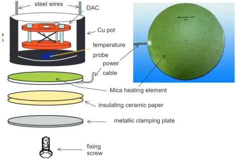
3 Experimental details 29 3.1 Techniques for high pressure . . . 29
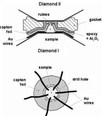
3.1.1 The diamond anvil cell . . . 29
3.1.2 Large volume cell . . . 33
3.2 High pressure experimental methods . . . 34
3.2.1 Electrical resistivity . . . 34
3.2.2 Magnetization . . . 36
3.2.3 Energy dispersive x-ray diffraction . . . 37
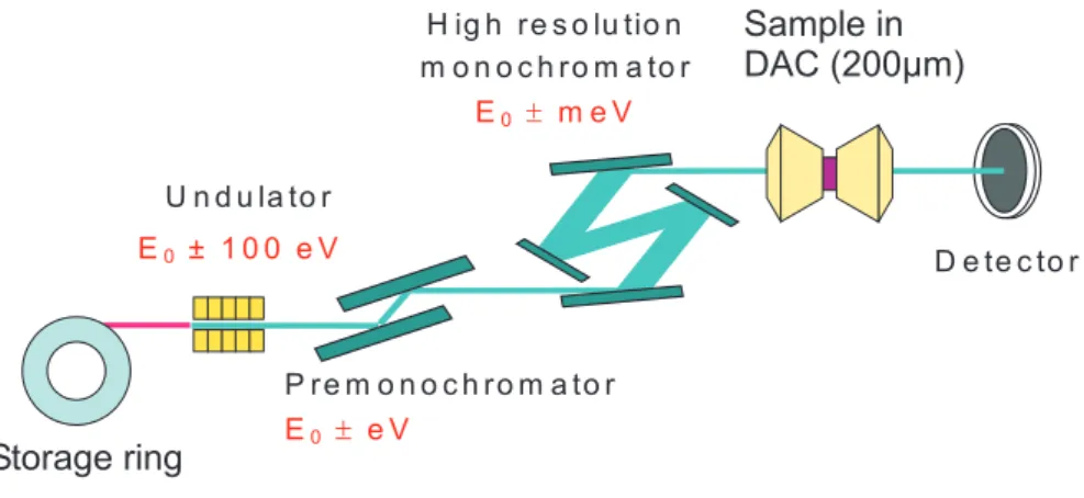
3.2.4 K β x-ray emission spectroscopy . . . 42
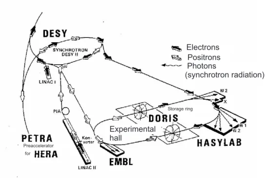
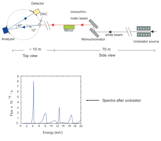
3.2.5 Nuclear forward scattering of synchrotron radiation . . . 46
3.2.6 High resolution neutron diffraction . . . 49
4 High pressure studies on RNiO
351 4.1 Basic properties of RNiO
3at ambient pressure . . . 51
4.1.1 Structural aspects . . . 51
4.1.2 Electronic properties . . . 55
4.2 Temperature-induced metal-insulator transition . . . 57
4.2.1 RNiO
3phase diagram . . . 57
4.3 Previous high pressure work on RNiO
3. . . 64
v
vi Contents
4.4 Motivation for high pressure studies on RNiO
3. . . 67
4.5 Experimental Results on RNiO
3. . . 69
4.5.1 The pressure-induced insulator metal transition . . . 69
4.5.1.1 Electrical resistivity measurements on LuNiO
3and YNiO
3: . . . 69
4.5.1.2 Electrical resistivity measurements on EuNiO
3and SmNiO
3: . . . 73
4.5.2 Structural stability of RNiO
3at the pressure-induced insulator metal transition . . . 78
4.5.2.1 x-ray diffraction measurements on LuNiO
3and YNiO
378 4.5.2.2 x-ray diffraction measurements on EuNiO
3and SmNiO
379 4.6 Discussion . . . 83
4.6.1 Possible mechanism of the pressure-induced insulator metal transition in RNiO
3. . . 83
4.6.1.1 Change of structural parameters . . . 83
4.6.1.2 Influence of charge ordering . . . 86
4.6.2 Pressure dependence of T
Nin RNiO
3. . . 89
4.6.2.1 LuNiO
3and YNiO
3: . . . 89
4.6.2.2 EuNiO
3: . . . 92
4.6.2.3 Pressure-temperature phase diagram of LuNiO
3and EuNiO
3. . . 94
5 High pressure studies on La
0.82Sr
0.18CoO
399 5.1 Basic properties of La
1−xSr
xCoO
3at ambient pressure . . . 99
5.2 Results on La
0.82Sr
0.18CoO
3. . . 103
5.2.1 Pressure-induced metal insulator transition . . . 103
5.2.1.1 Pressure dependence of the electrical resistivity . . . 103
5.2.1.2 Crystal structure under pressure . . . 106
5.3 Discussion: Mechanism of the pressure-induced metal insulator tran- sition . . . 107
5.3.1 Change of structural parameters under pressure . . . 107
5.3.2 Change of Co
3+spin-state under pressure . . . 109
5.3.2.1 Effect of pressure on the Co magnetic moment . . . . 109
5.3.2.2 Microscopic evidence for a pressure-induced spin-state transition . . . 110
5.3.2.3 Qualitative model: Effect of the spin-state transition on electron hopping . . . 112
6 Summary and Outlook 115
Chapter 1 Introduction
One of the long-standing issues associated with strongly correlated 3d transition metal oxides (e.g. RMO
31
) is the microscopic origin of the metal insulator (MI) transition and the nature of the ground state. This is related to the fact, that in this class of materials the MI transition is driven by strong correlation effects associ- ated with the electron-electron interaction and the interplay between charge, orbital and spin degrees of freedom. The MI transition can be induced by varying the car- rier concentration, temperature, magnetic field and internal or external pressure [1].
Thus, studying such an interplay is a fundamental issue for a better understanding of the nature of the MI transition.
In this view, external pressure provides a unique tool to tune electronic and magnetic properties of these systems, by modifying the effective bandwidth (W ) of the tran- sition metal by changing the M–O bond length (d
M−O) and/or the M–O–M bond angle (θ). In manganese perovskites R
1−xA
xMnO
3(A = Ca, Sr, Ba), for example, it has been shown that increasing pressure decreases d
M n−Oand increases θ. Both variations lead to an increase of W and thereby stabilize the ferromagnetic metallic state [2, 3, 4].
Another example, which demonstrates the effect of pressure on the charge degree of freedom, is the recent observation in Sr
2/3La
1/3FeO
3of a pressure-induced transi- tion from the charge ordered antiferromagnetic insulating state to a charge-uniform ferromagnetic metallic state [5].
The aim of this thesis is to investigate the effect of pressure on the transport, mag- netic and structural properties of RNiO
3and (La,Sr)CoO
3perovskites, that recently attracted considerable interest due to their unique electronic and magnetic proper- ties.
Unlike manganites, RNiO
3oxides are placed at the boundary separating low-∆
metals (∆ is the charge transfer energy) and the charge transfer insulators. An
1
R = rare earth ion, M = transition metal ion
1
2 Chapter 1. Introduction exciting consequence of this is that the occurrence of the metal insulator transition in RNiO
3series requires neither electron nor hole doping. The MI transition can be induced as a function of temperature and the transition temperature (T
M I) in- creases with decreasing size of the R
3+ions (T
M I= 130 K (Pr),..., 600 K (Lu)). For R = La the system remains metallic down to lowest temperatures, whereas for R 6 = La electron localization occurs. The temperature-induced MI transition in RNiO
3series has been ascribed to the opening of a small charge transfer gap at T < T
M I[6, 7] which is intimately connected with a structural phase transition (distortion) from orthorhombic P bnm to monoclinic P 2
1/n [8]. The transition to a monoclinic symmetry upon crossing T
M Ito the insulating state implies the formation of two different Ni-sites and the presence of a charge ordering (2Ni
3+→ Ni
3+δ+ Ni
3−δ) [8, 9].
Another interesting aspect of RNiO
3is that for larger R
3+ions (R = Pr, Nd) the MI transition is accompanied by an antiferromagnetic (AF) ordering of the Ni sublattice (i.e. T
N≈ T
M I), whereas for smaller R
3+(R = Sm → Lu) T
Nis much smaller than T
M I(e.g. for EuNiO
3, T
N= 220 K and T
M I= 463 K). According to the magnetic phase diagram RNiO
3exhibit a crossover from antiferromagnetic insulator (R 6 = La) to nonmagnetic metal (R = La) through a quantum critical point (QCP) [10].
As external pressure is expected to close the small charge transfer gap in RNiO
3, it should result in a pressure-induced insulator to metal (IM) transition. High pressure studies should therefore provide valuable information on the driving mechanism of the MI transition. In particular, the interplay between charge ordering and local structure as well as the crossover from the antiferromagnetic insulating state to the metallic nonmagnetic state.
High pressure experiments have been performed on RNiO
3with R = Sm, Eu, Y and Lu using different experimental techniques (electrical resistivity, x-ray diffrac- tion and complementary magnetization,
151Eu nuclear forward scattering using syn- chrotron radiation and high resolution neutron diffraction). The results of these measurements are presented and discussed in chapter 4.
The new aspect that distinguishes (La,Sr)CoO
3from RNiO
3and other RMO
3ox- ides is that the Co
3+ions possess in addition to the usual degrees of freedom an extra degree of freedom, namely the possibility to change the spin-state of Co
3+- ions. This can occur if the crystal-field energy ∆
CFand the intraatomic exchange energy J
ex(Hund’s rule coupling) are comparable. Such a delicate balance leads to spin-state transitions which can be induced by changing the temperature or com- position [11, 12, 13]. The rhombohedral perovskite La
1−xSr
xCoO
3(0 ≤ x ≤ 0.5) represents an exemplary series in which, contrary to conventional Mott insulators, the ground state of the undoped insulating system (LaCoO
3) is nonmagnetic with a low spin (LS, S = 0) state which can be thermally excited to either high spin (HS, S
= 2) or an intermediate spin (IS, S = 1) state at T ≈ 100 K [14, 15, 16]. At higher
3 temperatures around 500 K the system undergoes a MI transition. However, by doping with Sr
3+, the ground state becomes ferromagnetic for x ≥ 0.18 (through a spin-glass-like region between 0 < x < 0.18; at the same time the electrical conduc- tivity increases with increasing x and for x ≃ 0.2 the system undergoes a transition to a metallic state [17, 18, 19, 20, 21]. It is generally accepted, that replacing La
3+by Sr
2+creates formally Co
4+ions and the double exchange between Co
4+and the
remaining Co
3+leads to a ferromagnetic coupling [19, 22]. Little is known, however,
about the correlation between the spin and charge degree of freedom near the MI
transition, i.e. whether and to what extent these spin-state transitions affect the MI
transition. To provide an answer to the above given questions, high pressure experi-
ments using different experimental techniques have been performed on single crystal
of conducting, ferromagnetic La
0.82Sr
0.18CoO
3located near the boundary of the MI
transition. Electrical resistivity, x-ray diffraction, magnetization and inelastic x-ray
emission spectroscopy measurements have been used. The results are presented and
discussed in chapter 5. Conclusions of the thesis and an outlook for future work are
given in chapter 6.
Chapter 2
Theoretical background
2.1 Electronic states of transition metal ions in crys- tals
The degeneracy of d levels of a single transition metal (TM) ion (l = 2) is fivefold (2 l + 1). In a crystal, the spherical symmetry of the ion will be reduced due to the strong anisotropic crystal field (CF) and the fivefold orbital degeneracy is lifted.
This leads to a splitting of the energy levels and is called the crystal field splitting (∆
CF).
Figure 2.1 clarifies why the five d-levels in a crystal with octahedral symmetry become non-degenerate. The crystal field here particularly is determined by the Coulomb repulsion of the oxygen octahedra which surround the TM ions. In the schematic illustration the positions of the oxygen ions (which are called ligands) are located on the coordinate axes (x, y, z).
If the orbital of a TM d-electron is adjusted directly towards the oxygen p-orbital (Figure 2.1(a)), it experiences a higher energy due to the Coulomb repulsion than an electron in an orbital which is aligned between the ligand orbitals (Figure 2.1(b).
Thus, the d
x2−y2and d
z2orbitals which are considered as the e
g-orbitals and point directly to the oxygen are higher in energy than electrons of the d
xy, d
yzand d
xzorbitals with lobes between the orbitals of the ligand. They have a small probability density in the p-orbitals and thus are lower in energy. They are considered as the t
2g-orbitals and as well as the e
g-orbitals degenerated in an octahedral symmetry (Figure 2.1(c)).
This crystal field splitting between the t
2gand the e
glevels is often defined as 10Dq.
Typical values for the magnitude of the crystal field splitting are ∆
CF∼ 1 - 2 eV.
According to the above discussed Coulomb repulsion of localized electrons, one ob- tains an additional contribution to the crystal field splitting in the case of hybridiza-
5
6 Chapter 2. Theoretical background
d d
d d d
(a)
(b)
(c)
e (d , d )
t (d , d , d ) D = 10Dq
2/5 D 3/5 D 3d
isolated atom
octahedral environment
g x²-y² z²
x²-y² z²
xy xz yz
CF
CF CF
xy xz yz
2g
Figure 2.1: (a) The orbitals of the two e
glevels (d
x2−y2and d
z2) are directed towards the p-orbitals of the ligand, whereas the t
2g-orbitals (d
xy, d
yzand d
xz) are directed between the p-orbitals (b). Sign of the wave function: + = red; –
= blue. (c) Crystal-field splitting of a fivefold orbitally degenerate 3d level of an isolated ion in an octahedral crystal field.
tion between p and d-electrons of the oxygen and the TM ion. Since e
gorbitals have a large overlap with oxygen orbitals, a strong hybridization results which leads to the so-called σ-bonds (Figure 2.2 (a,b)). As a result, such hybridization shifts the e
glevels to higher energy by a contribution of
δE
eg∼ t
2pd∆ , (2.1)
where t
pdis the hopping matrix element between e
gand p orbitals and ∆ is the primarily energy difference between the p- and d-levels. This result can be estimated by second order perturbation theory, assuming the pd-hybridization - which can be described by the hopping matrix element t
pdbetween the e
g- and p-orbital - is small in comparison to the energy difference ∆ of the p- and d-states. It should also be mentioned, that the crystal field splitting induced by hybridization (∆
′CF) is always much larger than that induced by the Coulomb repulsion of two adjacent ions (∆
′CF> ∆
CF).
2.1 Electronic states of transition metal ions in crystals 7
Figure 2.2: The hybridization of d-levels of a TM ion with the p-orbital of a ligand leads to a splitting of the e
g- and t
2g-levels. (a,b) strong overlap and hybridization of the d
x2−y2- and d
z2-orbitals with the corresponding p
x- and p
z-orbitals of the oxygen (σ-orbital of the ligand). (c) Overlap and hybridization of the d
xz-orbital (one of the t
2g-orbitals) with corresponding p
z-orbital of the oxygen (π-hybridization). (d) Scheme of energy levels modified by the hy- bridization. Note, that ∆
′CF> ∆
CF. Sign of wave functions: + = red; – = blue.
Furthermore, t
pdalso depends on the TM-O-TM bond angle, which can be described in a first approximation by
t
dd= (t
pdσ)
2∆ cos θ, (2.2)
where t
ddis the electron hopping between two bend d-states in a pervoskite structure across a σ-bonded p-orbital.
It is possible to make these considerations for the t
2g-orbitals as well. As shown in Figure 2.1, the t
2g-orbitals are orthogonal to the p-orbitals and therefore, the lobes of d-orbitals are orientated to the adjacent TM ion and not to the oxygen.
For further discussion, it is important to note the signs of the d wave functions,
which are illustrated in different colors in Figure 2.1 and 2.2. These are irrelevant
for the Coulomb interaction with the ligands, giving a point-charge contribution to
8 Chapter 2. Theoretical background the CF, but play an important role further on. Because of symmetry reasons, the overlap between the p
σ- and t
2g-orbitals disappears - this is clear since the overlap with opposite sign is equal. The remaining overlap is shown in Figure 2.2(c) and known as the π-hybridization. Generally, this overlap is allowed by symmetry but it is much weaker than the overlap of e
g-orbitals with oxygen p
σ. Therefore, the energy shift of the t
2g-states, due to the (t
2g− p)-hybridization, is significantly less.
In Figure 2.2(d) the modified energy scheme is presented. Clearly to see, that due to
the pd-hybridization the t
2gset together with the e
gset are shifted to much higher
energy and the degenerated p-levels are decreased in energy.
2.2 Ordering phenomena in transition metal oxides 9
2.2 Ordering phenomena in transition metal oxides
2.2.1 Spin state transition
If we now consider the ground state of a TM ion and distribute all its d-electrons according to Hund’s rule, we can put as many electrons with the same spin configu- ration in the CF-split levels as possible. For d
2- d
9systems we furthermore have to take care of the electron-electron interactions; but to simplify matters they should be neglected here exceptionally. In d
1- d
3systems, Hund’s rule predicts that the electrons will not pair and occupy the whole t
2glevels. In comparison to that, in d
4electron systems for example exist two possibilities: Three electrons can occupy the t
2glevels and one the e
glevel, so that the electrons do not pair. This situation is called the high spin (HS) state. Or all electrons occupy the t
2glevels and therefore are partially paired. This is the so-called low spin (LS) state. Both cases are illus- trated in Figure 2.3.
e
gt
2gD
CFe
gt
2gD
CFFigure 2.3: Spin states of a d
4transition metal ion: (a) high-spin (HS) state; (b) low-spin (LS) state
The question of which state will be realized, either HS or LS, is determined by the ratio of ∆
CFand the Hund’s coupling energy J
H. For both HS and LS states, it is possible to compute the CF coupling energy as a function of number of electrons and strength of the CF.
If for instance ∆
CF> 3J
H(which is shown in Figure 2.3(b)), then a LS state will be favored and the spins will occupy the lowest CF levels at the expense of Hund’s rule exchange. In the opposite case the HS state will be favored. In other words,
∆
CF/J
Hin LS states is larger than ∆
CF/J
Hin HS states.
Another important fact due to the realization of either HS or LS is, that the ionic
radius of TM ions in HS is different than the ionic radius in LS. For example the HS
ionic radius of Co
3+is 0.61 Å in contrast to 0.545 Å in the LS state [23]. A related
situation occurs in Fe
3+systems where the HS ionic radius of Fe
3+is 0.645 Å in
comparison to 0.55 Å in the LS state [23]. This may lead to serious consequences if
a system, e.g. CaFe
4+O
3, which is presented in HS state and external pressure will
10 Chapter 2. Theoretical background be applied. Then pressure leads to a reduction of the volume and the ionic radius, respectively which results in a HS → LS phase transition. This has been observed for pressures p ≥ 30 GPa [24]. A more extensive discussion about the influence of pressure on the properties of TM ions will be given in chapter 5 and 6.
In the huge field of TM oxides most of them such as e.g. Mn
3+(d
4in LaMnO
3) occupy HS state as ground state, comparable to the situation in Figure 2.3(a). Here the large splitting has a crucial consequence: whereas the three electrons in the t
2glevels are localized to the ion, the single e
gelectron can move free through the crys- tal. It is itinerant and provides the metallic conductivity. Furthermore, it carries its spin through the whole crystal and adjusts the spins of the t
2gelectrons. This also influences the magnetism in LaMnO
3.
However, there are notable exceptions in which not HS as ground state is realized.
For instance, the ionic states of Co
3+(d
6), Ni
3+(d
7) and Ru
4+(d
4) are often LS states. Also by changing the parameters such as temperature, pressure and compo- sition of the material, different spin states may appear, even real phase transitions as the material crosses over from one state to another may occur. This may be the situation in LaCoO
3[25] for which even a more complicated situation may exist, with the stabilization of an intermedidate spin (IS) state [14], see Figure 2.4(b).
e
gt
2gD
CF(b) (c)
(a)
Figure 2.4: Possible electronic configurations of Co
3+and Fe
2+both with (d
6config- uration): (a) low-spin (LS) state; (b) intermediate spin (IS) state and (c) high-spin (HS) state.
The existence of an IS state is also discussed in doped LaCoO
3. The series La
1−xSr
xCoO
3suppresses rapidly the non-magnetic ground state and leads to a ferromagnetic order
with increasing Sr-doping, whereas the resistivity decreases and leads to a metallic
conductivity [21].
2.2 Ordering phenomena in transition metal oxides 11
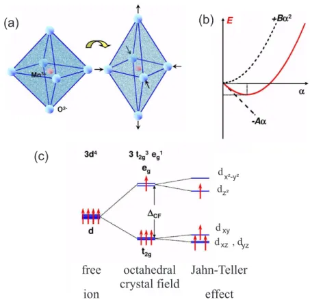
2.2.2 Jahn-Teller effect and orbital ordering
The Jahn-Teller theorem [26, 27] states that a system of interacting electrons and nuclei in a degenerated electronic state is unstable, because the system can always reduce its energy by distorting in such a way as to remove the degeneracy [28].
The linear reduction in energy due to the removal of degeneracy will ultimately be balanced by the initial quadratic increase in elastic energy [29] and a new position of equilibrium will be reached with a permanent distortion of the system. This means that e.g. a regular octahedra may be deformed into a tetragonal distortion to lift the cubic symmetry, see Figure 2.5(a). The energy gain as a function of a distortion α can then be described by perturbation theory as
E(α) = − Aα + Bα
22 (2.3)
Here the first term denotes the splitting of the degenerate levels due to a pertur- bation whereas the second term denotes an elastic deformation energy. A can be considered as the electron-phonon coupling, B describes the bulk modulus. As a result, one obtains a minimum in energy at some finite α, see Figure 2.5(b).
For the cubic Mn
3+-ion in LaMnO
3for instance, a possible distortion consists of an elongation of the oxygen octahedron by the value of 2α in z-direction and a common compression of α in x- and y-direction. The splitting of the energy levels caused by the Jahn-Teller effect (see Figure 2.5(c)) can be understood in a similar way like the crystal field. Elongation in z-direction reduces the Coulomb repulsion between the ligands and the electrons in the d
z2-orbital. This leads to an energy reduction of the d
z2-orbital. In contrast to this, a compression of the octahedron in xy-plane yields to a stronger Coulomb repulsion for an electron in the d
x2−y2-orbital, and results in an increase of energy. This means, that the d
z2-orbital will be energetically lower than the d
x2−y2.
The neighbors of TM ions in perovskites experience the deformation forces and in- teract with a corresponding deformation since they have common oxygen ligands.
This leads to a reduction of the crystal symmetry, i.e. a structural phase transition.
This effect is called the cooperative Jahn-Teller effect or orbital ordering. Orbital ordering means a fixed pattern of orbital occupations at every atomic site in the crystal.
If all the O
6-octahedra are elongated in one direction, one speaks of a ferrodistortion or ferroorbital ordering, like in Mn
3O
4or in Mn ferrites. Even in some cases (e.g.
LaMnO
3, see Figure 2.6) these orbitals are aligned perpendicular to each other due
to the distortion and this leads to a configuration which is known as the antiferro-
orbital ordering.
12 Chapter 2. Theoretical background
(a) (b)
free ion
octahedral crystal field
Jahn-Teller effect (c)
d
z²d
x²-y²d d
xzxy
, d
yzFigure 2.5: Tetragonal deformation of O
6-octahedra stabilizing one particular orbital:
(a) Elongation: stabilizing d
z2-orbital (and vice versa a compression: sta- bilizing d
x2−y2-orbital). (b) A perturbation α reducing the symmetry: a linear term which represents the splitting of the degenerated levels (energy gain) and a quadratic term representing the energy loss. (c) Splitting of the energy levels of the d-orbitals of a Mn
3+-ion due to the crystal field and the Jahn-Teller effect. Taken from [30].
Orbital ordering due to the cooperative Jahn-Teller effect occurs in many compounds
containing typical Jahn-Teller active ions like Mn
3+(d
4), Cr
2+(d
4), LS Ni
3+(d
7), or
Cu
2+(d
9). Since the strong hybridization of TM ion and p-orbital of the ligand, the
splitting of the e
g-level together with an energetical shift from the adjacent oxygen
is rather strong, which gives rise to a strong Jahn-Teller coupling.
2.2 Ordering phenomena in transition metal oxides 13
Figure 2.6: Orbital structure and shifts of oxygen ions in LaMnO
3: Antiferroorbital
ordering with locally elongated octahedra packed so that the long axes al-
ternate in the basal plane. The distortion helps to minimize the total strain
of the crystal.
14 Chapter 2. Theoretical background
2.2.3 Charge ordering
The phenomenon of charge ordering in transition metal oxides is very important with respect to the electric and structural properties of the system. Ions of a par- ticular class of compounds can suddenly change from a homogeneous intermediate valence state to charge disproportionated valence state in which the charge orders in a periodic way. This often leads to a metal-to-insulator transition. The origin of charge ordering is the Coulomb repulsion U between the carriers. If U exceeds a certain value, the charge carriers arrange themselves in a way that they have the largest possible distance from each other. Nevertheless, the electron-lattice interac- tions can often play a crucial role too, since the charge carriers in an ionic crystal are often accompanied by a distortion of the surrounding ligands. For example, the system La
1−xSr
xFeO
3with x ≈ 2/3 shows below 210 K a disproportionation of the Fe
4+valence into 2Fe
4+→ Fe
3++ Fe
5+and an antiferromagnetic spin or-
Figure 2.7: Spontaneous magnetization (M
S), electric resistivity (ρ) and magnetic sus-
ceptibility (χ) for La
0.33Sr
0.67FeO
3as a function of temperature [34].
2.2 Ordering phenomena in transition metal oxides 15 dering [31, 32, 33]. Whereas LaFeO
3is an antiferromagnetic insulator (3d
5, S = 5/2, T
N= 738 K), on the other end SrFeO
3is an antiferromagnetic metal with T
N= 134 K [34]. Figure 2.7 shows that below T
Nthe electric resistivity ρ of La
1−xSr
xFeO
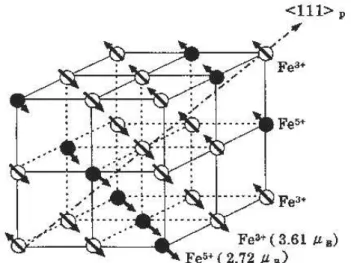
3increases dramatically about more than 6 orders in magnitude, indi- cating the appearance of a first-order phase transition. This is the charge-ordering (CO) phase transition with simultaneous antiferromagnetic spin ordering and was first observed in this compound by Mössbauer spectroscopy [31] and confirmed by neutron-scattering measurements [33]. This electronic phase transition proved to be the simultaneous charge and spin ordering in a superlattice structure is presented in Figure 2.8. Here, the disproportionated charges are condensed within the (1 1 1) plane in the cubic perovskite structure.
Figure 2.8: Schematic structure of the charge- and spin-ordered state with charge dis-
proportionation in La
1−xSr
xFeO
3with x ≈ 0.67
16 Chapter 2. Theoretical background
2.3 Exchange interactions in magnetic oxides
Up to now we mainly have considered the electronic properties of isolated TM ions in crystals (charge, spin, orbital ordering and Jahn-Teller effect) with their properties arising from an interaction between the ions. The magnetic interactions in such systems are of special interest, since they cause long-range magnetic ordering as well as the possibility of electron transfer from one site to another [35]. The easiest model describing the interplay between localization and band formation in a solid is the one-band Hubbard model [36].
2.3.1 The Hubbard model
According to the discussion of electronic structure of doped manganites in the pre- vious section, we have neglected the spin interactions. But these interactions are of fundamental importance since they are responsible for magnetic ordering states which are observed in experiments. Now we will also include these relevant magnetic interactions in doped manganites into discussion. These considerations can also be used for the most other TM oxides. The magnetic dipole-dipole interaction between spins of adjacent Mn-ions generally is rather weak and plays no role. In contrast to this, exchange processes are of fundamental importance due to the realization of a long-range ordered magnetic ground-state. In such processes electrons (and with them their spins) have a certain probability to hop to their next neighbor’s site and reduce the energy of the system hereby. This hopping of electrons is important for the magnetic interactions as well as for the electric transport.
Finally, we are looking for a highly oversimplified model for electrons in a solid which interact with each other through extremely short-ranged repulsive (Coulomb) interaction [37, 38]. Origin of the discussion should be a lattice, where a single electron with spin S = 1/2 (either with ↑ or ↓ ) sits on each lattice site and has exactly one level of disposal. That electron could be for example the e
g-electron of LaMnO
3. This scenario can be well described by the Hubbard model:
H = H
t+ H
U(2.4)
The first term of the Hamiltonian expresses the quantum mechanical hopping of electrons in a conduction band of width W , thus the kinetic energy.
H
t= − t X
hiji,σ
(c
†iσc
jσ+ c
†jσc
iσ). (2.5)
The operators c
†iσand c
jσare standard fermionic creation and annihilation operators
for an electron with spin σ (σ either ↑ or ↓ ) at site i and j , respectively. The matrix
element t
ijdetermines the nature of this hopping. In most cases only hopping
between adjacent neighbors h i, j i with a hopping amplitude − t is considered. The
amplitude of the hopping is negative in order to emphasize the gain in kinetic energy
2.3 Exchange interactions in magnetic oxides 17 of the system due to the hopping. The second term considers the local Coulomb interaction U between the electrons.
H
U= U X
i
n
i↑n
i↓(2.6)
The operator n
iσcounts the electrons with spin σ at site i. For U ≪ t the Hamil- tonian describes a metallic state
H
t= X
ε
kc
†iσc
jσwith ε
k= − 2t(cos k
x+ cos k
y+ cos k
z). (2.7) Hereby we assume the simplest tight-binding approximation for the band dispersion with hopping only between next neighbors in a simple cubic lattice.
In the case of U ≫ t, the contribution of H
Ugoverns in the Hubbard model. An electron which hops to its neighbor site of course gains some energy t, but it has to overbear the much larger energy U. Thus, the energetically most favorable state is that without manifold occupation, i.e. single occupied. This is a localized state and describes the Mott-Hubbard insulator which will be discussed later.
Since H
Ualone contains no linkages of different lattice sites, the energy of that with H
Ulinked state does not depend on the orientation of the surrounding other spins.
As a result, a magnetically ordered state can not be realized with H
Ualone. But this will change soon, if hopping between the sites is allowed. The electrons can now gain kinetic energy ( h H
ti < 0), but have to bring up the potential energy ( h H
Ui ).
These excited states can now be added to the ground state, so that a reduction of the energy may occur. (This formally conforms a covalent bonding.) The energy gain can be determined in second order perturbation theory (t/U ≪ 1) and is of order t
2/U [39].
Additionally a tendency of antiferromagnetic spin ordering occurs, which can be easily understood by the following consideration: If two electrons on adjacent lattice sites have the same spin, hopping is forbidden due to Pauli’s exclusion principle. Do they have opposite spins, hopping is allowed. This is schematically demonstrated in Figure 2.9 with two d
z2-orbitals. One electron hops to its neighbor and back with matrix element t. According to second order perturbation theory this results in an energy gain of ∆E = -2t
2/U. The contribution H
tin equation (2.4) comes twice, from where the t
2in the counter results from. In the denominator the energy of the virtual intermediate state is written and the factor of 2 comes from the fact that the left spin can hop to the right and the right to the left. As a result a configuration with antiparallel spins is preferred relative to the one with the parallel spins and thus an antiferromagnetic ground state. This can be described as an effective exchange interaction:
H
ex= J
exX (S
iS
j) with J
ex= 4t
2U . (2.8)
18 Chapter 2. Theoretical background
(a)
(b)
0
= DE
U E t
2
2- µ D
Figure 2.9: Two neighboring d
z2orbital with (a) parallel and (b) antiparallel spin. The energy gain due to the virtual hopping of an electron to a neighboring site is shown.
In other words, the virtual hopping of electrons leads to an antiferromagnetic Heisen- berg exchange interaction which is usually known as the kinetic exchange or superex- change
1(see section 2.6). Thus, Pauli’s principle obviously has a significant fraction of the antiferromagnetic correlations of the electrons in the lattice, since two elec- trons may not occupy the same level.
1
Strictly speaking, this expression stands for an analog interaction of magnetic ions via a dia-
magnetic ion.
2.4 Charge-transfer and Mott-Hubbard insulators 19
2.4 Charge-transfer and Mott-Hubbard insulators
In our discussion up to now, we have assumed that the electron hopping from one site to another is straightforward. But this is not the case in real TM oxides like LaMnO
3. The hopping between the Mn-sites occurs via the intermediate oxygen ion. But in many cases this detail is not very important. Thus, we can say that neighboring ions (e.g. Mn
3+) still interact, if one electron in an orbital at a particular lattice position has a certain probability density in the orbital of its neighbor - whatever hopping is directly from orbital to orbital or via intermediate orbitals. This is the main essence of the above introduced hopping between lattice points with the transfer integral J
exin (2.8). If the orbitals do not overlap, t is equal zero. Therefore, the hopping t finally is an indicator for the degree of hybridization between two adjacent orbitals. Obviously, it is sufficient to consider only the outer ionic orbitals, i.e. the 3d orbital of the TM ion and the 2p orbital of the oxygen ligand, since the overlap to energetically lower orbitals is clearly less.
However, if we take the d-electrons of the TM ion as well as the p-electrons of the oxygen into account, the Hamiltonian can be described in the following form:
H = X
ε
dd
†iσd
iσ+ ε
pp
†jσp
jσ+ t
pd(d
†iσp
jσ+ h.c.) + Un
di↑n
di↓. (2.9) Here the operators d
†iand d
ias well as p
†iand p
iare the creation and annihilation operators for an electron at the TM ion site and the oxygen site, respectively. ε
pand ε
dare the energies of the 2p- and 3d-states, whereas t
pddescribes the hopping between the p- and d-orbitals. Responsible for the hopping between 3d-orbitals via the oxygen 2p-orbitals is the energy difference between the 2p-orbitals to the 3d’s.
This energy gap ∆ := ε
d− ε
pis known as the charge-transfer energy.
Now it is possible to distinguish two cases, depending on the charge-transfer excita- tion energy ∆ and the Coulomb repulsion U . This situation is schematically shown in Figure 2.10.
(i) ∆/U ≫ 1, the Mott-Hubbard insulator:
If the oxygen 2p-orbitals are low in energy (Figure 2.10 (a)), ∆ will be much larger than U, then the lowest charged excited states are those which correspond to the transfer of a d-electron from one TM site to another: d
n+ d
n→ d
n−1+ d
n+1. This process costs the energy U . As we have seen above, we obtain an insulating ground state for U ≫ W (W denotes the bandwidth), which is known as a Mott-Hubbard insulator. Certainly, this hopping does not happen directly from one TM ion to the next, but via the oxygen p-states. With some support of perturbation calculations it is possible to introduce an effective d − d hopping matrix element
t ≡ t
dd= t
2pd∆ , (2.10)
20 Chapter 2. Theoretical background
energy
(a) Mott-Hubbard insulator:
D = |ed- ep|
Wd eF Fermi-level
inter- actionU
p-band d-band
Udd
charge gap
energy
(b) Charge-transfer insulator:
Wd
charge gap
D Wp
d-band
p-band Wd
eF Fermi-level
inter-
actionU Udd
Figure 2.10: Schematic view of a Mott-Hubbard insulator and charge-transfer insulator, reproduced from [1]. In the case of ignored hybridization between p- and d-bands and multiple effects, the magnitude of the energy gap E
gin Mott- Hubbard insulators can be written as E
g= U
dd− W
d= U − 2zt = U − ∆ and for charge-transfer insulators as E
g= ∆ −
Wp+W2 d, where W
pand W
dis the bandwidth of the p- and d-band, respectively and z denotes the coordination number of the ligand.
which can be taken into account of the simple Hamiltionian (2.5).
(ii) ∆/U ≪ 1, the charge-transfer insulator:
If on the other hand the 2p-orbitals are close to the 3d-levels (Figure 2.10(b)), ∆ becomes much smaller than U and the lowest charged excited states are those where an electron of a 2p-level will be transferred into a 3d-level of an adjacent TM ion.
Therefore results in a hole at the oxygen site. For one electron per TM ion and
∆/t ≫ 1, we obtain again an insulating ground state, which is defined as charge- transfer insulator. In the simplest case, such a state will be antiferromagnetic, with the only difference being in the exchange integral J
ex(2.8) which will be expressed now as
J
ex= 2(t
2pd/∆)
22∆ + U
pp= 2t
22∆ + U
pp. (2.11)
Here, it is necessary to take the effective hopping matrix element t from eq. (2.10) and the energy (2∆ + U
pp) of the virtual intermediate state, whereas U
ppdescribes the Coulomb repulsion of two holes at the oxygen lattice site.
Thus, from the point of view of magnetic properties, there is no significant dif- ference between charge-transfer insulators and Mott-Hubbard insulators. However, differences appear in their excitation spectra as well as in their transport properties.
Further effects are discussed in detail in [40, 41] and used for the description of some
2.4 Charge-transfer and Mott-Hubbard insulators 21 real materials, e.g. CrO
2in [42].
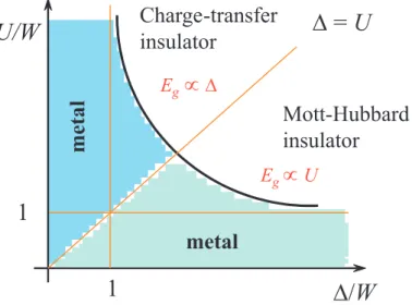
According to this two limiting cases, Zaanen, Sawatzky and Allen [43] suggested the following phase diagram:
D/W U/W
1
1
D = U
metal
m e ta l
Charge-transfer insulator
Mott-Hubbard insulator
E
gµ D
E
gµ U
Figure 2.11: General Zaanen-Sawatzky-Allen phase diagram which separates Mott- Hubbard insulators from charge-transfer insulators.
For U/W > ∆/W the band gap is of p − d type and the anion or ligand p-band is lo- cated between the lower and upper Hubbard bands. This gap is a charge-transfer gap and the corresponding compounds (NiO, FeO, LaMnO
3, etc.) are charge-transfer insulators. In this case, the band gap is proportional to ∆.
If U/W < ∆/W , the band gap is of d − d type and thus a Mott-Hubbard insulator.
They have a band gap of the magnitude U . The straight line U = ∆ separates
the Mott-Hubbard and the charge-transfer regimes. The diagram also contains a
metallic region near the ∆/W -axis (d-metals as TiO, YTiO
3) or near the U/W -
axis (p-metal as V
2O
3). This classification scheme is very useful for oxide materials
science. More examples can be found in a review article of Imada [1].
22 Chapter 2. Theoretical background
2.5 Goodenough-Kanamori-Anderson rules
In the discussion of the magnetic exchange interaction in sections 2.3 & 2.4 we have examined only the simplest case of an electron in a non-degenerate or twofold de- generate d-orbital. In fact, this consideration for real materials often is too simple and has to be extended by the structure of the orbitals. Since the details of orbital structure determine e.g. the overlap with the oxygen 2p-states and possible orbital degeneracy. Thus, the consideration of magnetic interactions can be very complex.
Goodenough, Kanamori and Anderson [25, 44] formulated easy rules in order to predict in the most cases the right magnetic exchange interactions. In the follow- ing the Goodenough-Kanamori-Anderson (GKA) rules will be discussed on LaMnO
3. As we have seen above, the d − d overlap occurs via bridging of the oxygen p-electrons.
Because of this, one has to regard the geometry of the relevant orbitals which are schematically illustrated in Figure 2.12. Here, the oxygen p-orbital is occupied by two electrons and directed towards or overlap with the Mn-ion. The electrons of the Mn (3d
4) ion will be distributed in a difficult way: three electrons will occupy the t
2g-levels and generate a so-called core spin of S = 3/2, i.e. these electrons will stay at the Mn-atomic site and create a local spin. The fourth electron instead will oc- cupy the energetically most favorable e
g-level, due to the benefit of the Jahn-Teller effect. In octahedral elongated systems it favors the d
z2-orbital and can hop. The three arrows in Figure 2.12 denotes the core spin of the three t
2gelectrons. Here in this example, the d
z2-orbitals are directed towards the oxygen ions. As a result, one obtains three different options how to occupy these orbitals which finally lead to the three GKA-rules.
The first GKA-rule says, that the 180
◦-exchange between filled or empty orbitals is relatively strong and antiferromagnetic. The conclusion of this is illustrated in Figure 2.12(a,b). Both Mn ions have one (or none) electron in opponent adjusted d
z2-orbitals, so that sometimes one speaks of the 180
◦-exchange between half-filled orbitals, having in mind that there is one electron at each orbital, and not two!
If the electrons in both Mn-O bonds hop like in a single level lattice, the itinerant spins of the adjacent Mn ions in the d
z2-orbitals will align antiparallel. Since of the strong intraatomic Hund’s coupling, the core spins have to be parallel to the according itinerant spins: i.e. the interaction between the magnetic moments of the Mn-sites finally is antiferromagnetically.
The second GKA-rule says, that when the 180
◦-exchange is due to an overlap be- tween an occupied and an empty orbital, the resulting exchange is ferromagnetic and relatively weak. This rule is illustrated in Figure 2.12(c). The difference to (a) is that the bond of the oxygen and the Mn ion on the left and right hand side is different.
On the left hand side the bond is analog to (a), but on the right side the d
z2-orbital
of the Mn ion is unoccupied and the corresponding orthogonal d
x2−y2-orbital is oc-
2.5 Goodenough-Kanamori-Anderson rules 23
Figure 2.12: To clarify the Goodenough-Kanamori-Anderson rules, the d
x2−y2- (shad- owed), and the d
z2-orbitals (to the left and right) as well as the p
z-orbitals in the center of a Mn-O-Mn bonding are schematically illustrated. The small arrows in the orbitals describe the itinerant electrons, the three ar- rows outside the orbital denote the total core spin S = 3/2 of the three not shown t
2gorbitals. According to the realized occupation, either an antiferromagnetic (AF) (a,b) or a ferromagnetic (FM) (c,d) coupling will be established. [30].
cupied. Thus, the p-electron of the oxygen can hop into the empty d
z2-orbital. The energetically most favorable configuration is reached when the electron will be build in with parallel spin, according to Hund’s first rule. Instead of this, the p-electron on the left hand side prefers an antiferromagnetic ordering. As a result, the Mn spins order ferromagnetically.
The third GKA-rule says, the 90
◦-exchange between (half-) filled orbitals is ferro-
magnetic and relatively weak. Figure 2.12(d) shows the 90
◦-exchange between filled
orbitals. Here, the hopping happens between a p
z-orbital and the left Mn ion and
between a p
y-orbital and the right Mn ion. This means, that two holes remain in the
oxygen in the virtual intermediate state. Due to the orientation of the Mn spins, the
24 Chapter 2. Theoretical background two remaining electrons on the oxygen site have either a parallel or an antiparallel spin orientation.
Since the energy of the intermediate state is commonly written in the denominator of the corresponding energy, the state with the lowest energy will be favored. According to Hund’s first rule, this is the state with parallel spin configuration of the electrons (or holes) at the oxygen site. Thus, the spins of the two Mn-ions are parallel, too.
Then the energy difference between the parallel and antiparallel configuration is given by:
J ≃ − 2t
4pd∆
21
2∆ + U
p− J
H− 1 2∆ + U
p≃ − t
4pd∆
2(2∆ + U
p)
J
H(2∆ + U
p) (2.12) where J
Hmeans the Hund’s coupling energy and U
pthe Coulomb repulsion between the two p-orbitals.
Together with these considerations it is now possible to explain the magnetic order- ing of LaMnO
3, if we assume orbital odering in that way which is already shown in Figure 2.6. For more clearness the oxygen and unoccupied d
x2−y2orbitals are not drawn. As we can see easily, in the horizontal plane an half-filled orbital is directed towards an unoccupied orbital, which means that the layers order ferromagnetically.
Between the planes always empty orbitals overlap and this leads to an antiferromag-
netically ordering.
2.6 Superexchange and double exchange interactions 25
2.6 Superexchange and double exchange interactions
In the following section we want to describe two important effects on which the pre- vious introduced GKA-rules are based. Since magnetic dipole-dipole interactions between spins of adjacent Mn-ions generally are rather weak, exchange processes to establish a long range magnetic ordered ground states will be ascribed an important role. In such processes electrons and their related spins are able to hop from site to site and hereby reduce the energy of the system.
Exchange interaction between degenerated levels:
Considering a situation where one electron is taken at each lattice site. The new aspect now is that two energetically degenerated levels are free to be occupied. This is of high relevance for real crystals since at the lattice sites are ions with multiple degenerated levels, e.g. the e
glevels of LaMnO
3without Jahn-Teller distortion. If one electron occupies one of these levels, another electron a different level, we, thus, declare in this model, that electrons occupy different single particle states. In this case, two electrons at the same lattice site may have the same spin without violating Pauli’s exclusion principle. Figure 2.13 presents the four possible configurations of two adjacent sites ’left’ and ’right’ with the two degenerated levels d
z2and d
x2−y2. The arrows represent the spins of the electrons in their corresponding orbitals. In the following it is necessary to replace t by t
ijin H
tof equation (2.5). To simplify matter we assume that t
ij= t for i = j and t
ij= 0 if i 6 = j. This is a good ap- proximation if the two considered orbitals are orthogonal to each other, so that the overlap and therefore the hopping between the orthogonal orbitals vanishes
2. In Figure 2.13(a) Pauli’s principle forbits a transfer of the electron, which leads to no change in energy (∆E = 0). In case (b) and (c) the gain in energy is similar to the above in section 2.3.1 discussed and is ∝
2tU2.
If in the case of Figure 2.13(d) the electron hops from left to right, it has to bring up the Coulomb energy U, but wins the Hund’s coupling energy J
H(in manganite compounds ≈ 1.5 eV). Because of Hund’s coupling energy, configuration (d) is the energetically most favorable state. From the orientation of the spins in (d) one can immediately conclude, that ferromagnetic correlations of the spins of adjacent Mn-ions exist, in contrast to the one-level lattice in the previous section 2.3.1.
Simultaneously the occurrence of an orbital ordering will be favored. To transfer this result on LaMnO
3two small difficulties appear. Firstable, a Mn-ion has more than only one electron in its 3d-shell and second, between the Mn-ions are O
2−-ions, so that primary these Mn-spins can not interact directly. Instead of this, an inter- action via the diamagnetic ion will be realized.
2
This means, that the electrons can not hop into the shadowed orbital (see Figure 2.13).
26 Chapter 2. Theoretical background
Figure 2.13: Schematic illustration of the superexchange in case of two-fold degenera- tion with respect of Hund’s coupling for opposite directed d
z2- and related d
x2−y2-orbitals (shadowed). The most favorable configuration leads to fer- romagnetic correlations [40].
As a result, an energy difference between antiparallel (b,c) and parallel (d) spin configuration can be evaluated, according to equation (2.8) an effective exchange constant J
exwhich is
J
ex≃ 2t
2U − 2t
2U − J
H= 2t
2J
HU
2− J
H· U ≃ 2t
2U
J
HU . (2.13)
Here we have taken into account, that commonly U ≫ J
H. As one can see, one gets a ferromagnetic exchange which is rather weak due to J
H/U ≪ 1.
The double exchange interactions
In 1951 Zener [45] offered an explanation for the behavior of the indirect magnetic
exchange between 3d atoms. He considered that the intraatomic Hund rule exchange
was strong and that the carriers do not change their spin orientation when hopping
from one ion to the next, so they can only hop if the spins of the two ions are
parallel. On minimizing the total free energy of the system, Zener found that ferro-
magnetic interactions are favored when the magnetic atoms are fairly well separated
2.6 Superexchange and double exchange interactions 27 and conduction electrons are present. The theory was applied to the manganese per- ovskites [45] with the aim of explaining the strong correlation between conductivity and ferromagnetism, and the value of the zero-temperature saturation magnetiza- tion which corresponds to the sum of all the unpaired electron spins. Starting from the insulating antiferromagnetic LaMnO
3end member where electrons are localized on the atomic orbitals, Zener showed how the system should gradually become more ferromagnetic upon hole doping (introduction of Mn
4+). He considered the problem of the exchange between Mn
3+and Mn
4+ions via an oxygen ion and introduced the concept of simultaneous transfer of an electron from the Mn
3+to the oxygen and from the oxygen to the neighboring Mn
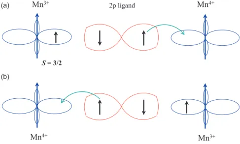
4+, which is schematically shown in Figure 2.14. Such a transfer is called double exchange.
2p ligand
S= 3/2
Mn
3+Mn
4+Mn
4+Mn
3+(a)
(b)
![Figure 2.7: Spontaneous magnetization (M S ), electric resistivity (ρ) and magnetic sus- sus-ceptibility (χ) for La 0.33 Sr 0.67 FeO 3 as a function of temperature [34].](https://thumb-eu.123doks.com/thumbv2/1library_info/3700671.1505981/22.892.253.589.524.985/spontaneous-magnetization-electric-resistivity-magnetic-ceptibility-function-temperature.webp)