• Keine Ergebnisse gefunden

COMICS: A Modular, Configurable Confocal Microscope Control Software

N/A
N/A
Protected

Academic year: 2021

Aktie "COMICS: A Modular, Configurable Confocal Microscope Control Software"

Copied!
152
0
0

Wird geladen.... (Jetzt Volltext ansehen)

Volltext

(1)

Helmut Hörner

COMICS:

A Modular, Configurable

Confocal Microscope Control Software

Project Report

TU Wien

Institute of Atomic and Subatomic Physics

Vienna, January 2021

(2)

Abstract

This paper presents the ’Confocal Microsccope Control Software’, or COMICS for short. It was devel- oped by the author in course of a technical physics master studies project at the Vienna Institute of Atomic and Subatomic Physics.

COMICS is based on the Qudi software framework, and is separated into a User Interface Layer, a Logic Layer, and a Hardware Layer. Especially the separated Hardware Layer allows for easy integration of new hardware components, if required. This paper gives a brief introduction into the confocal micro- scope hardware currently controlled by the COMICS software, then a detailed description of the software architecture and the software interfaces, followed by installation instructions, configuration instructions and a user’s guide.

(3)

Contents

1 Introduction 9

2 The Confocal Microscope Hardware Design 10

2.1 Axes Orientation . . . 13

3 COMICS Software Design 14 3.1 Introduction to the Qudi Framework . . . 14

3.2 COMICS software architecture overview . . . 15

4 Interfaces for Hardware Layer Classes 17 4.1 ati_positioner_interface . . . 17

4.1.1 get_name() . . . 17

4.1.2 set_name(new_name) . . . 17

4.1.3 get_pos_ch_count() . . . 18

4.1.4 get_pos_axis_count(channel_cnf) . . . 18

4.1.5 get_pos_device_name(channel_cnf) . . . 18

4.1.6 get_pos_range(channel_cnf) . . . 19

4.1.7 get_pos_axes(channel_cnf) . . . 19

4.1.8 set_pos_position(channel_cnf, x=None, y=None, z=None, a=None) 20 4.1.9 get_pos_position(channel_cnf, extra_precision=1) . . . 21

4.1.10 get_pos_target_position(channel_cnf) . . . 22

4.1.11 pos_matches_target_position(self, channel_cnf, xyz, pos) . . . . 22

4.1.12 get_pos_ini_position(channel_cnf, xyz) . . . 23

4.1.13 pos_provides_cur_pos_info() . . . 23

4.1.14 pos_is_moving(channel_cnf) . . . 24

4.1.15 pos_is_resetting(channel_cnf) . . . 24

4.1.16 pos_allows_homing(channel_cnf) . . . 24

4.1.17 pos_home(channel_cnf) . . . 25

4.1.18 pos_trigger_queue(channel_cnf) . . . 25

4.1.19 get_pos_default_unit(channel_cnf) . . . 25

4.1.20 get_pos_precision(channel_cnf) . . . 26

4.1.21 get_pos_steps_default(channel_cnf, axis_cnf) . . . 26

4.1.22 get_pos_steps_min(channel_cnf, axis_cnf) . . . 27

4.1.23 get_pos_steps_max(channel_cnf, axis_cnf) . . . 27

4.1.24 close_positioner() . . . 27

4.2 ati_counter_interface . . . 28

4.2.1 get_name() . . . 28

4.2.2 set_name(new_name) . . . 28

4.2.3 get_pcnt_sources_count() . . . 28

4.2.4 get_pcnt_channel_count(source_cnf) . . . 29

4.2.5 get_pcnt_channel_names(source_cnf) . . . 29

4.2.6 get_pcnt_rate(source_cnf) . . . 30

(4)

4.2.7 update_cur_count_rate(output_source_cnf, channel_idx) . . . . 30

4.2.8 get_last_cnt_rates() . . . 31

4.2.9 close_counter() . . . 31

4.3 ati_camera_interface . . . 32

4.3.1 get_name() . . . 32

4.3.2 is_connected() . . . 32

4.3.3 get_size() . . . 32

4.3.4 get_resolutions() . . . 33

4.3.5 set_resolution(res_index) . . . 33

4.3.6 start_single_acquisition(wait_for_acquisition) . . . 34

4.3.7 is_acquiring() . . . 34

4.3.8 stop_acquisition() . . . 34

4.3.9 get_acquired_data() . . . 35

4.3.10 get_ready_state() . . . 35

4.3.11 set_cooler(state) . . . 35

4.3.12 is_cooler_on() . . . 35

4.3.13 set_temperature(temp) . . . 36

4.3.14 provides_temperature_information() . . . 36

4.3.15 get_temperature() . . . 36

4.3.16 get_temperature_precision() . . . 37

4.3.17 set_exposure(exposure) . . . 37

4.3.18 get_exposure(get_actual_val_from_hardware = True) . . . 37

4.3.19 get_max_exposure() . . . 37

4.3.20 has_shutter() . . . 38

4.3.21 get_shutter_settings() . . . 38

4.3.22 get_default_shutter_setting() . . . 38

4.3.23 set_shutter(index) . . . 38

4.3.24 get_additional_settings() . . . 39

4.3.25 set_additional_settings(ID, value) . . . 41

4.4 ati_actuator_interface . . . 42

4.4.1 get_name() . . . 42

4.4.2 set_name(new_name) . . . 42

4.4.3 get_act_ch_count() . . . 42

4.4.4 get_act_ch_name(ch_cnf) . . . 43

4.4.5 get_act_ch_output(ch_cnf) . . . 43

4.4.6 get_act_ch_is_digital(ch_cnf) . . . 44

4.4.7 set_act_output(ch_cnf, value) . . . 44

5 Logic Layer Class Interface 45 5.1 Remarks on Absolute and Relative Coordinates . . . 45

5.2 General Scan Methods . . . 45

5.2.1 get_scan_type_count() . . . 45

5.2.2 get_scan_type_max_index() . . . 46

5.2.3 get_scan_type_name(scan_type) . . . 46

(5)

5.2.4 set_cur_scan_type_index(scan_type) . . . 46

5.2.5 get_cur_scan_type_index() . . . 46

5.2.6 set_scan_center_position(scan_type, x=None, y=None, z=None, a=None, absolute = False) . . . 47

5.2.7 set_scan_X_range(scan_type, new_range, absolute = False) . . . 48

5.2.8 set_scan_Y_range(scan_type, new_range, absolute = False) . . . 49

5.2.9 set_scan_Z_range(scan_type, new_range, absolute = False) . . . 50

5.2.10 get_scan_range(scan_type, xyz, absolute = False) . . . 51

5.2.11 matches_target_position(scan_type, xyz, pos, absolute = False) . 52 5.2.12 set_scan_resolution(scan_type, xyz, new_res) . . . 53

5.2.13 same_scan_resolution(scan_type, xyz_1, xyz_2) . . . 54

5.2.14 get_scan_resolution(scan_type, xyz) . . . 55

5.2.15 get_min_resolution(scan_type, xyz) . . . 56

5.2.16 get_max_resolution(scan_type, xyz) . . . 57

5.2.17 start_scanning(scan_type, depth_scan = False, tag = ’logic’) . . 57

5.2.18 stop_scanning() . . . 58

5.2.19 continue_scanning(depth_scan, tag = ’logic’) . . . 59

5.2.20 cur_scan_is_depth_scan() . . . 59

5.2.21 get_cur_main_scan_continuable() . . . 60

5.2.22 get_cur_depthscan_continuable() . . . 60

5.2.23 get_main_scan_image(scan_type) . . . 61

5.2.24 get_depth_scan_image(scan_type) . . . 62

5.2.25 get_scan_counter() . . . 63

5.2.26 get_ax_index_from_xyz_index(d, scan_type, xyz) . . . 64

5.2.27 get_third_scan_axis_xyz_index(scan_type, d) . . . 65

5.2.28 allows_depth_scan(scan_type) . . . 65

5.2.29 save_file(scan_type, file_name, main_image) . . . 66

5.2.30 load_file(scan_type, file_name) . . . 67

5.3 Main Positioning Device Control Methods . . . 68

5.3.1 set_position(tag, scan_type=-1, x=None, y=None, z=None, a=None, absolute = False) . . . 68

5.3.2 get_position(scan_type = -1, absolute = False) . . . 69

5.3.3 get_target_position(scan_type, absolute = False) . . . 70

5.3.4 pos_provides_cur_pos_info(scan_type) . . . 71

5.3.5 get_pos_range(scan_type, xyz, absolute = False) . . . 72

5.3.6 set_pos_ini_position(scan_type, main_axes, absolute_center) . . 73

5.3.7 get_pos_ini_position(scan_type, xyz, absolute, absolute_center) 73 5.3.8 get_pos_is_centered(scan_type, main_axes) . . . 74

5.3.9 absolute_pos_coords_available(scan_type) . . . 74

5.3.10 pos_abs_to_rel(scan_type, xyz, pos_abs) . . . 75

5.3.11 pos_rel_to_abs(scan_type, xyz, pos_rel) . . . 76

5.3.12 get_pos_length_unit(scan_type) . . . 76

5.3.13 get_pos_precision(scan_type) . . . 77

5.3.14 get_pos_axes(scan_type = -1) . . . 77

(6)

5.3.15 get_pos_ch_device_name(scan_type, first_char_upper) . . . 78

5.4 Pre-Positioning Device Control Methods . . . 78

5.4.1 set_pre_position(scan_type, x=None, y=None, z=None, a=None, absolute = False) . . . 79

5.4.2 get_pre_pos_position(scan_type, absolute = False) . . . 80

5.4.3 pre_pos_allows_homing(scan_type) . . . 81

5.4.4 pre_pos_home(scan_type) . . . 81

5.4.5 get_pre_pos_ini_position(scan_type, xyz, absolute = False) . . . 82

5.4.6 absolute_pre_pos_coords_available(scan_type) . . . 82

5.4.7 pre_pos_abs_to_rel(scan_type, xyz, pos_abs) . . . 83

5.4.8 pre_pos_rel_to_abs(scan_type, xyz, pos_rel) . . . 83

5.4.9 pre_pos_trigger_queue(scan_type) . . . 84

5.4.10 get_pre_pos_length_unit(scan_type) . . . 84

5.4.11 get_pre_pos_precision(scan_type) . . . 85

5.4.12 matches_pre_pos_target_position(scan_type, xyz, pos, absolute = False) . . . 85

5.4.13 get_pre_pos_range(scan_type, xyz, absolute = False) . . . 86

5.4.14 get_pre_pos_axes(scan_type = -1) . . . 87

5.4.15 get_pre_pos_ch_device_name(scan_type, first_char_upper) . . 87

5.5 Camera Control Methods . . . 88

5.5.1 is_camera(scan_type) . . . 88

5.5.2 cam_is_connected(scan_type) . . . 88

5.5.3 get_cam_resolutions(scan_type) . . . 89

5.5.4 set_cam_resolution(scan_type, res_index) . . . 89

5.5.5 cam_has_shutter(scan_type) . . . 90

5.5.6 get_cam_shutter_settings(scan_type) . . . 90

5.5.7 get_cam_default_shutter_setting(scan_type) . . . 91

5.5.8 set_cam_shutter(scan_type, mode) . . . 91

5.5.9 set_cam_exposure(time, scan_type=-1) . . . 92

5.5.10 get_cam_exposure(scan_type) . . . 92

5.5.11 get_cam_max_exposure(scan_type) . . . 93

5.5.12 cam_provides_temperature_information(scan_type) . . . 93

5.5.13 cam_get_temperature_precision(scan_type) . . . 94

5.5.14 cam_get_temperature(scan_type) . . . 94

5.5.15 cam_start_acquistion(scan_type, first_call) . . . 95

5.5.16 cam_wait_for_acquisition_end(scan_type) . . . 96

5.5.17 cam_is_acquiring(scan_type) . . . 97

5.5.18 cam_fetch_image(scan_type) . . . 98

5.5.19 get_last_cam_image() . . . 99

5.5.20 cam_stop_acquistion(scan_type) . . . 99

5.5.21 get_additional_cam_settings(scan_type) . . . 100

5.5.22 set_additional_cam_setting(scan_type, id, value) . . . 102

5.6 Photon Counter Control Methods . . . 103

5.6.1 get_pcounter_channel_names(scan_type, default="") . . . 103

(7)

5.6.2 get_cur_pcounter_channel_names() . . . 103

5.6.3 get_cur_pcounter_rate(scan_type, ch_idx) . . . 104

5.7 Signals . . . 104

5.7.1 signal_xy_image_updated(scan_type) . . . 104

5.7.2 signal_depth_image_updated(scan_type) . . . 104

5.7.3 signal_cam_update_display(scan_type) . . . 104

5.7.4 signal_cam_acquisition_finished() . . . 104

5.7.5 signal_change_position(tag) . . . 105

6 Software Installation and Configuration 105 6.1 Installation of all Components and Drivers . . . 105

6.1.1 Install Git for Windows . . . 105

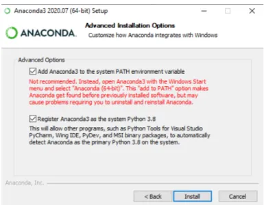
6.1.2 Install Anaconda . . . 105

6.1.3 Install PyCharm . . . 106

6.1.4 Copy COMICS Source Code and Install Python Modules . . . 106

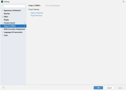
6.1.5 First Start and Configuration of PyCharm . . . 107

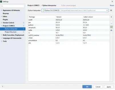
6.1.6 Install Python Modules in Python 3.6 Environment . . . 109

6.1.7 Install NI PyDAQ Driver Software . . . 110

6.1.8 Install PI Driver and Configuration Software . . . 110

6.1.9 Install Thorlabs Kinesis Driver Software . . . 111

6.1.10 Install Swabian Time Tagger Driver Software . . . 112

6.1.11 Install Andor SDK Software . . . 113

6.1.12 Create Desktop Shortcut Icon . . . 115

6.2 Software Configuration . . . 116

6.2.1 Kinesis Positioner . . . 116

6.2.2 PI Positioner . . . 118

6.2.3 NI Card . . . 120

6.2.4 Swabian Time Tagger . . . 124

6.2.5 Andor Camera . . . 127

6.2.6 Kinesis Actuators . . . 129

6.2.7 COMICS Logic Module . . . 130

6.2.8 COMICS User Interface . . . 137

7 User’s Guide 138 7.1 Start Qudi and COMICS . . . 138

7.2 Camera Scan Mode . . . 140

7.2.1 Image Settings . . . 140

7.2.2 Extended Camera Settings . . . 140

7.2.3 Pre-Positioning . . . 141

7.2.4 Temperature . . . 142

7.2.5 Color Scale Setting . . . 142

7.2.6 Display Settings . . . 142

7.2.7 Crosshair Position Controls . . . 143

7.2.8 Taking a Snapshot . . . 144

(8)

7.2.9 Live Video Acquisition . . . 144

7.3 Confocal Scan With Two-Axes Positioning-Device (e.g. Mirror Scan) . . . 145

7.3.1 Scan Resolution Settings . . . 145

7.3.2 Scan Range Settings . . . 146

7.3.3 Pre-Positioning . . . 146

7.3.4 Count Rate . . . 146

7.3.5 Color Scale Setting . . . 146

7.3.6 Display Settings . . . 147

7.3.7 Crosshair Position Controls . . . 147

7.3.8 Start a Scan . . . 148

7.3.9 Stop and Resume a Scan . . . 149

7.4 Confocal Scan With Three-Axes Positioning-Device (e.g. Stage Scan) . . 149

7.4.1 Main Scan Pre-Positioning . . . 150

7.4.2 Depth Scan Pre-Positioning . . . 151

7.4.3 Cross Hair Position Controls . . . 151

7.4.4 Starting and Stopping Main-Scan and Depth-Scan . . . 152

7.5 Saving and Loading Images . . . 152

7.6 Saving Images . . . 152

7.7 Loading Images . . . 152

(9)

1 Introduction

This paper presents the COMICS software package. COMICS is an acronym for ’Con- focal Microscope Control Software’. The software was developed by the author in course of a technical physics master studies project at the Institute of Atomic and Subatomic Physics in Vienna.

Whereas the primary design goal for the COMICS software package was to meet the immediate requirements of controlling a confocal microscope newly designed and built at the Institute of Atomic and Subatomic Physics, it was an equally important design-goal to ensure a high level of flexibity and modularity so that potential future modifications or enhancements of the hardware can be easily accommodated.

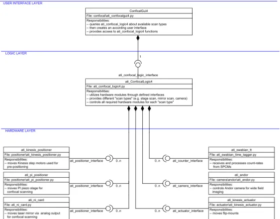
As we show in this paper, the COMICS software is strictly separated into a User Inter- face Layer, a Logic Layer, and a Hardware Layer. Especially the separated Hardware Layer allows for easy integration of new hardware components in the future, if required.

For example, there is a defined software interface between Logic Layer and Hardware Layer for controlling any type of positioning device, like, for example, laser mirrors, piezo stages or stepper motors.

If any of these positioning hardware components will change in the future, it will only be required to add a matching hardware module for the newly added single hardware component into the otherwise unchanged software package. The same goes for photon counter hardware, camera hardware or actuators (like flip mounts), for which also ref- erence hardware modules have been implemented.

A configuration file, defining which hardware components should be accessed and used for which type of scan (or camera imaging) adds an extra level of flexibility.

The following chapter gives a brief introduction into the confocal microscope hardware

at the Institute of Atomic and Subatomic Physics in Vienna for which the COMICS

software has been primarily developed. After that, we give a detailed description of the

software architecture and the software interfaces, followed by installation instructions,

configuration instructions and a user’s guide.

(10)

2 The Confocal Microscope Hardware Design

The confocal microscope for which the COMICS software has been developed for imme- diate application has the following features:

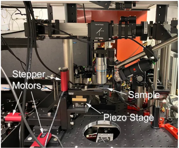
The sample is to be placed on a sample holder on top of a PI piezo stage, which is controlled by an E-727 piezo microcontroller from Physik Instrumente GbmH. The con- troller is connected to the computer via USB. The stage has a range of 100 µm in x, y, and z direction. To allow pre-positioning, the whole stage itself can be moved in the millimeters range along all three axes with three Thorlab Kinesis stepper motors (see figure 1).

Figure 1: Stepper motors, piezo stage and sample holder

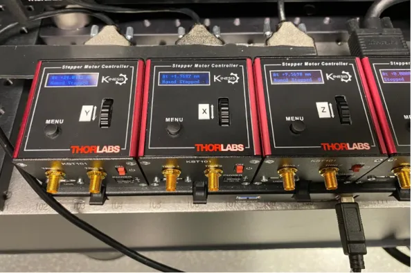
Each of the stepper motors is controlled by a K-Cube Stepper Motor Controller. These

controllers all connect to the PC via a Thorlab K-Cube USB Controller Hub (see fig-

ure 2).

(11)

Figure 2: K-Cube Stepper Motor Controllers

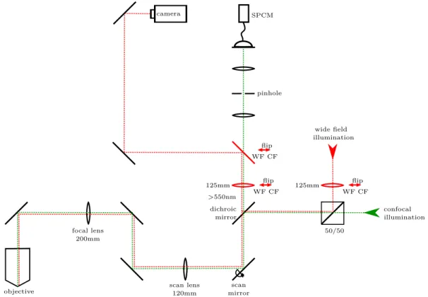
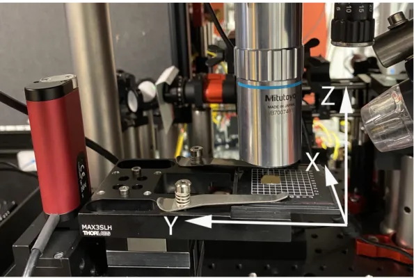
In its final configuration, the confocal microscope will include two main beam paths for an objective facing the sample from top, and another objective facing the sample from below. As of completion of this paper, only the objective facing the sample from above is included and operable. In this upper beam path, the beam is guided from the objective (50 × ) via an total reflective mirror through a 200 mm focal lens and a scan lens towards a laser scan mirror.

This laser scan mirror offers an alternative method for scanning the sample. It is con- trolled by a piezo controller, which reacts to analog voltage signals from a NI (National Instruments) IO card plugged directly into the personal computer. Also, analog voltage signals indicating the current actual position are fed back into the NI IO card from the controller.

For imaging, the beam path leads through a dichroic mirror which separates the fluores- cence from the excitation beam. For first applications it reflects light with wavelength λ < 550 nm and transmits light of wavelength λ > 550 nm. This allows to filter out and (further down) detect light coming from molecular fluorescence emitters.

There are two ways of imaging: Firstly, the confocal microscope allows to take wide-field

images with an Andor iXon Ultra 897 camera from Oxford Instruments, connected to

the computer via USB. The corresponding beam path is depicted with a red dotted line

(12)

in figure 3, and must be switched active with a flipmount mirror (red movable mirror in figure 3).

In wide-field mode, a 125 mm lens is moved into the wide-field illumination path (right red movable lens in figure 3), so that there is a focus on the back focal plane of the objec- tive, and consequently a collimated light beam comes out of the objective. An equivalent lens must also be added to the imaging path in wide field mode (left red movable lens in figure 3).

Secondly, there is the confocal mode, depicted with the green dotted line in figure 3. The confocal imaging beam path leads through a pinhole between two lenses (see figure 3).

Then outcoming collimated beam finds its way to a COUNT 50N Single Photon Count- ing Module (SPCM) from Laser Components, connected to a Time Tagger (Swabian Instruments) device. The Time Tagger device is connected to the computer via USB.

focal lens 50/50

200mm

objective 4mm

scan lens 120mm

scan mirror

confocal illumination wide field

illumination

125mm

WF CF 125mm flip

WF CF flip

dichroic mirror

>550nm

WF CF flip pinhole camera SPCM

Figure 3: Beam paths in the confocal microscope. The confocal beam path is displayed

in green, the wide-field beam-path in red. The two movable lenses and the

movable mirror displayed in red color are depicted in the wide-field imaging

position, and must be flipped out of the beam-path for confocal imaging.

(13)

2.1 Axes Orientation

The orientation of the scan axes is generally subject to both the specific hardware as well as to the specific configuration.

Having said that, Fig. 4 shows the orientation of axes of the confocal microscope hard- ware at the Institute of Atomic and Subatomic Physics in Vienna according to the software configuration as of January 2021.

Figure 4: orientation of axes according to current configuration (Jan. 2021)

Please note that the x-axis and y-axis directions refer to features on the sample. This

means, for example, that features more on the left side of the sample are located at ever

larger values of the y-axis. However, the according stage movement during a stage-scan

has to be necessarily towards the opposite direction: The stage must move right (towards

negative y-direction) so that features on the left side of the sample come into the scan

focus. The same is analogously true for the x-axis.

(14)

3 COMICS Software Design

3.1 Introduction to the Qudi Framework

The COMICS software package is based on the Qudi framework, which defines itself to be "a Python software suite for controlling complex experiments and managing the acquisition and processing of measurement data" (see [Binder et al, 2017, p. 86]).

The Qudi framework allows a collection of software modules to be loaded and connected to one another by a manager component according to the settings specified in a config- uration file.

A Qudi session proceeds as follows: A user starts the start.py file. This loads the core components that take care of configuration parsing, module management, and error logging. The module manager reads a configuration file to determine which modules should be launched and configured for a specific experiment. (see Fig. 5a).

Figure 5: Qudi functional and structural design. From: [Binder et al, 2017, p. 87]

Experiment software modules in Qudi are divided into three categories: hardware mod- ules, experiment "logic", and user interface. These categories and the relationships be- tween them are illustrated in Figure 5b.

All logic modules connect down to hardware modules via well-defined interfaces. This means that a logic module does not care about specific hardware details, as long as a matching hardware module implementing the required interface is available.

It is noteworthy that a hardware module may implement multiple interfaces; e.g. an

analog/digital IO hardware module may implement an interface for positioning an laser-

mirror via it’s analog output channels, as well as another interface for registering counts

from an SPCM via its digital input lines.

(15)

3.2 COMICS software architecture overview Figure 6 gives an overview of the COMICS architecture:

Figure 6: COMICS software architecture

When starting the user interface from the Qudi module manager, an instance of class ConfocalGui4 is created. On instancing the class determines from the corresponding section of the Qudi configuration file to which logic module it should connect to.

The logic module class implementing the ati_confocal_logic_interface is ati_ConfocalLogic4 . After instancing, this class retrieves all so-called scan types from the corresponding section in the Qudi configuration file. Each scan types has a unique name (e.g. "Mirror Scan" or "Stage Scan"), and the configuration file determines which positioning hardware should be used for each of these scan types .

Also, the configuration file determines for each scan type the hardware modules through

which count-rates should be received, and (optionally) which positioning hardware should

be used for pre-positioning. Further, a control sequence can be stored in the configura-

tion file for each scan type , specifying actions for actuators to be executed before a scan

(16)

is started.

Wide field imaging through a camera module is also supported and can be integrated as a separate scan type . In such case, instead of positioning and photon-counting hardware classes, a camera hardware module class is referenced.

On startup, the GUI class instance of ConfocalGui4 queries the connected ati_ConfocalLogic4 class instance about number, name and features of all scan types , and builds up the graphical user interface correspondingly (with a tab for each scan type and all required user controls).

Depending on the hardware component classes referenced in the corresponding configuration-file section of each scan type , the ati_ConfocalLogic4 class instance will connect to various hardware modules by means of well-defined class interfaces.

Every positioning hardware is accessed through a class implementing the ati_positioner_interface . Currently, the following module classes implement this interface:

• The ati_kinesis_positioner class for controlling Kinesis stepper motors;

• the ati_PI_positioner class for controlling a PI piezo stage; and

• the ati_ni_card class for controlling a piezo mirror by means of analog IO chan- nels.

The following hardware module classes have been additionally implemented:

• The ati_sqbian_tt class with an ati_counter_interface , allowing access to the Swabian time-tagger hardware for retreiving and processing SPCM count-rates;

• the ati_andor class with an ati_camera_interface , providing access to Andor cameras;

• and the ati_kinesis_actuator class with an ati_actuator_interface , allowing

to control Kinesis flip-mounts.

(17)

4 Interfaces for Hardware Layer Classes

In this chapter we describe the above-mentioned interfaces for the various hardware module classes.

4.1 ati_positioner_interface

The ati_positioner_interface needs to be implemented by all hardware module classes used for controlling positioning devices like stages, mirrors, stepper motors, etc.

This chapter describes the required class methods comprising the interface.

4.1.1 get_name()

Returns a string with the name of the positioning device. This method is expected to return a meaningful name already after the class has been instanced.

Return value:

• str : name of device.

See also:

• set_name(new_name)

• get_pos_device_name(channel_cnf) 4.1.2 set_name(new_name)

This method can be used to change the name of the device.

Parameter:

• str new_name : new name of the device.

See also:

• get_name()

(18)

4.1.3 get_pos_ch_count()

A single instance of a class implementing this ati_positoner_interface can not only be connected to a single positioning device, but (potentially) also to a controller that actually controls several positioning devices simultaneously. An example for that would be an analog IO card controlling two separate laser mirrors (each with two axes).

Each device is accessed through a separate "channel", numbered from 1 to n (with n being the number of devices). The method get_pos_ch_count() returns the number of channels (hence, the number of controllable devices):

Return value:

• int : number of channels, i.e.: number of controllable positioning devices.

4.1.4 get_pos_axis_count(channel_cnf )

This function returns the number of axes of the device identified by channel index channel_cnf .

Parameter:

• int channel_cnf : Channel index identifying the device. Must be larger or equal 1 and smaller or equal the number of available channels as returned by get_pos_ch_count() .

Return value:

• int : number of axis.

4.1.5 get_pos_device_name(channel_cnf )

In case an instance of a class implementing this interface is representing multiple posi- tioning devices simultaneously, the get_name() method is not sufficient, as it returns only one name.

In such case, method get_pos_device_name(channel_cnf) can be used to get the spe- cific name of the individual positioning device identified by channel index channel_cnf . Parameter:

• int channel_cnf : Channel index identifying the device. Must be larger or equal 1

and smaller or equal the number of available channels as returned by

get_pos_ch_count() .

(19)

Return value:

• str : name of positioning device.

See also:

• get_name()

4.1.6 get_pos_range(channel_cnf )

This method returns the physical range of all axes of the positioning device identified by channel index channel_cnf .

Parameter:

• int channel_cnf : Channel index identifying the device. Must be larger or equal 1 and smaller or equal the number of available channels as returned by get_pos_ch_count() .

Return value:

• list[n][2] : A list with n entries (where n is the number of axes of the positioning device identified by channel index channel_cnf ). Each entry consists of another list with two float values, representing the lower and upper bound of the axis’

physical range in meters.

4.1.7 get_pos_axes(channel_cnf )

This function returns a list containing the names of all axes of the positioning device identified by channel index channel_cnf .

Parameter:

• int channel_cnf : Channel index identifying the device. Must be larger or equal 1 and smaller or equal the number of available channels as returned by get_pos_ch_count() .

Return value:

• list[n] : A list with n entries (where n is the number of axes of the positioning

device identified by channel index channel_cnf ). Each entry consists of a string

value with the name of the corresponding axis (e.g. [’X’,’Y’,’Z’] ).

(20)

4.1.8 set_pos_position(channel_cnf, x=None, y=None, z=None, a=None)

This method moves the positioner referenced by channel index channel_cnf along one or more axes. The target positions of the axes to be moved must be passed on to the method via the four optional parameters x , y , z , and a ; where x stands for the devices’

first axes, y stands for the devices’ second axes, z stands for the devices’ third axes (if available) and a stands for any potentially available fourth axes (if available). Please note that the actual naming of the axes as returned by get_pos_axes(channel_cnf) may differ from " x ", " y ", and " z ".

By default, the device should start to move immediately after this method has been called. However, it may also happen that the device is a slow-moving positioning de- vice (like, stepper motors) and is currently re-setting (e.g. homing). Then, the move- ment is delayed and can be triggered at a later point in time by calling the method pos_trigger_queue(channel_cnf) .

Parameters:

• int channel_cnf : Channel index identifying the device. Must be larger or equal 1 and smaller or equal the number of available channels as returned by get_pos_ch_count() .

• optional float x : Target position of the first axis (in meters). Must be within the range returned by get_pos_range(channel_cnf)[0] .

• optional float y : Target position of the second axis (in meters). Must be within the range returned by get_pos_range(channel_cnf)[1] .

• optional float z : Target position of the third axis, if available (in meters).

Must be within the range returned by get_pos_range(channel_cnf)[2] .

• optional float a : Target position of a potential fourth axes, if available (in meters). Must be within the range returned by get_pos_range(channel_cnf)[3] . See also:

• get_pos_position(channel_cnf, extra_precision=1)

• get_pos_target_position(channel_cnf)

• pos_matches_target_position(self, channel_cnf, xyz, pos)

• pos_is_moving(channel_cnf)

• pos_is_resetting(channel_cnf)

• pos_trigger_queue(channel_cnf)

(21)

4.1.9 get_pos_position(channel_cnf, extra_precision=1)

Provided the positioner referenced by channel index channel_cnf has sensors to determine the current actual position (which can be queried by calling pos_provides_cur_pos_info() ), this class method returns:

• information about the current position of all axes,

• information whether or not the current position of each axes currently matches the target position (withing tolerances), and

• for each axis information about how long the position already matches the target position within tolerances (or, zero, if not matching).

If the device does not have senors to determine the current actual position, this class method will just return the target position and assume that we are already on target.

Parameters:

• int channel_cnf : Channel index identifying the device. Must be larger or equal 1 and smaller or equal the number of available channels as returned by get_pos_ch_count() .

• optional float extra_precision=1 : Any value n > 1 handed over here will cause the "within tolerance" information to be n times more "picky". E.g. a value of 2 means that a current axis position will be considered to be within tolerance only if it is within 0 . 5 times the default tolerance.

Return values (tuple):

• float list[n] : A list with n entries, where n stand for the number of axes.

The list contains the current positions of each axis in meters. If the device has no sensors to determine the actual positions, the list will just contain the target positions. For each axis, the list contains the boolean

• bool list[n] : A list with n entries, where n stand for the number of axes. For each axis, the list contains True , if the current axis’ position is on target (within tolerance), otherwise False . If the device has no sensors to determine the actual positions, the list will just contain True values.

• float list[n] : A list with n entries, where n stand for the number of axes. For

each axis, the list contains the duration in seconds for which the actual position is

already matching the target position (within tolerance). If, for an axis, the current

position is not matching the target position, a value of 0

is returned. If the device has no sensors to determine the actual positions,

the list will just contain the duration in seconds since calling of

set_pos_position(channel_cnf, x=None, y=None, z=None, a=None) .

(22)

See also:

• set_pos_position(channel_cnf, x=None, y=None, z=None, a=None)

• pos_provides_cur_pos_info()

• get_pos_target_position(channel_cnf)

• pos_matches_target_position(self, channel_cnf, xyz, pos) 4.1.10 get_pos_target_position(channel_cnf )

This class method returns the target positions of the positioner referenced by channel index channel_cnf .

Parameter:

• int channel_cnf : Channel index identifying the device. Must be larger or equal 1 and smaller or equal the number of available channels as returned by get_pos_ch_count() .

Return value:

• float list[n] : A list with n entries, where n stand for the number of axes. The list contains the target positions of each axis in meters. If no target position has been defined for an axis, the list will contain an None entry for this axis.

See also:

• set_pos_position(channel_cnf, x=None, y=None, z=None, a=None) 4.1.11 pos_matches_target_position(self, channel_cnf, xyz, pos)

This class method can be used to determine whether a given position pos matches the target position of a specific axis of a specific device (plus/minus minor rounding devia- tions).

Parameters:

• int channel_cnf : Channel index identifying the device. Must be larger or equal 1 and smaller or equal the number of available channels as returned by get_pos_ch_count() .

• int xyz : Index identifying the axis. Must be larger or equal 0 and smaller the number of available axis as returned by len(get_pos_axes(channel_cnf)) .

• float pos : Position in meters to which the target position should be compared

to.

(23)

Return value:

• bool : True , if the given position pos matches the target position of the axis referenced by xyz_index of the device referenced by channel_cnf (plus/minus minor rounding deviations). False otherwise, or if pos is None , or if no target position has yet been set.

See also:

• set_pos_position(channel_cnf, x=None, y=None, z=None, a=None) 4.1.12 get_pos_ini_position(channel_cnf, xyz)

This class method can be used to determine the initial "neutral" position for a specific axis of a specific device.

Parameters:

• int channel_cnf : Channel index identifying the device. Must be larger or equal 1 and smaller or equal the number of available channels as returned by get_pos_ch_count() .

• int xyz : Index identifying the axis. Must be larger or equal 0 and smaller the number of available axis as returned by len(get_pos_axes(channel_cnf)) . Return value:

• float : Initial position for this axis in meters.

4.1.13 pos_provides_cur_pos_info() Return value:

• bool : True if the positioners controlled by this device can provide information about the actual current position, False otherwise.

See also:

• get_pos_position(channel_cnf, extra_precision=1)

• pos_matches_target_position(self, channel_cnf, xyz, pos)

(24)

4.1.14 pos_is_moving(channel_cnf ) Parameters:

• int channel_cnf : Channel index identifying the device. Must be larger or equal 1 and smaller or equal the number of available channels as returned by get_pos_ch_count() .

Return value:

• bool list[n] : A list with n entries, where n stand for the number of axes. For each axis, the list contains True if the positioner is still moving along the axis, or False otherwise. If the hardware does not provide this information, all list entries are always False .

See also:

• set_pos_position(channel_cnf, x=None, y=None, z=None, a=None)

• get_pos_position(channel_cnf, extra_precision=1) 4.1.15 pos_is_resetting(channel_cnf )

Parameters:

• int channel_cnf : Channel index identifying the device. Must be larger or equal 1 and smaller or equal the number of available channels as returned by get_pos_ch_count() .

Return value:

• bool list[n] : A list with n entries, where n stand for the number of axes. For each axis, the list contains True if the positioner is resetting along the axis, or False otherwise.

See also:

• pos_home(channel_cnf)

4.1.16 pos_allows_homing(channel_cnf ) Parameters:

• int channel_cnf : Channel index identifying the device. Must be larger or equal 1 and smaller or equal the number of available channels as returned by get_pos_ch_count() .

Return value:

• bool : True if the positioning device has a callable homing procedure, which moves all axis to a "home" position, or False otherwise.

See also:

• pos_home(channel_cnf)

(25)

4.1.17 pos_home(channel_cnf )

This class method triggers a "homing" procedure, which moves all axis to a "home" po- sition, provided the device controller has such a procedure.

Parameters:

• int channel_cnf : Channel index identifying the device. Must be larger or equal 1 and smaller or equal the number of available channels as returned by get_pos_ch_count() .

See also:

• pos_allows_homing(channel_cnf)

• pos_is_resetting(channel_cnf) 4.1.18 pos_trigger_queue(channel_cnf )

By default, the device should start to move immediately after the class method set_pos_position(channel_cnf, x=None, y=None, z=None, a=None) has been called. However, it may also happen that the device is a slow-moving positioning de- vice (like, stepper motors) and is currently re-setting (e.g. homing). Then, the move- ment is delayed and can be triggered at a later point in time by calling the method pos_trigger_queue(channel_cnf) .

Parameters:

• int channel_cnf : Channel index identifying the device. Must be larger or equal 1 and smaller or equal the number of available channels as returned by get_pos_ch_count() .

See also:

• set_pos_position(channel_cnf, x=None, y=None, z=None, a=None)

• pos_is_resetting(channel_cnf) 4.1.19 get_pos_default_unit(channel_cnf ) Parameters:

• int channel_cnf : Channel index identifying the device. Must be larger or equal 1 and smaller or equal the number of available channels as returned by get_pos_ch_count() .

Return value:

• string : The length unit to be used in an user interface (’m’. . . millimeters, ’u’. . . micrometers, ’n’. . . nanometers).

See also:

• get_pos_precision(channel_cnf)

(26)

4.1.20 get_pos_precision(channel_cnf ) Parameters:

• int channel_cnf : Channel index identifying the device. Must be larger or equal 1 and smaller or equal the number of available channels as returned by get_pos_ch_count() .

Return value:

• int : Number of decimal points to be display in an user interface when using the length unit as returned by get_pos_default_unit(channel_cnf) .

See also:

• get_pos_default_unit(channel_cnf)

4.1.21 get_pos_steps_default(channel_cnf, axis_cnf ) Parameters:

• int channel_cnf : Channel index identifying the device. Must be larger or equal 1 and smaller or equal the number of available channels as returned by get_pos_ch_count() .

• int axis_cnf : Index identifying the axis. Must be larger or equal 1 and smaller or equal the number of available axis as returned by len(get_pos_axes(channel_cnf)) . Return value:

• int : Suggested default number of steps along this axis in a scan process.

See also:

• get_pos_steps_min(channel_cnf, axis_cnf)

• get_pos_steps_max(channel_cnf, axis_cnf)

(27)

4.1.22 get_pos_steps_min(channel_cnf, axis_cnf ) Parameters:

• int channel_cnf : Channel index identifying the device. Must be larger or equal 1 and smaller or equal the number of available channels as returned by get_pos_ch_count() .

• int axis_cnf : Index identifying the axis. Must be larger or equal 1 and smaller or equal the number of available axis as returned by len(get_pos_axes(channel_cnf)) . Return value:

• int : Minimum number of steps along this axis in a scan process.

See also:

• get_pos_steps_default(channel_cnf, axis_cnf)

• get_pos_steps_max(channel_cnf, axis_cnf) 4.1.23 get_pos_steps_max(channel_cnf, axis_cnf ) Parameters:

• int channel_cnf : Channel index identifying the device. Must be larger or equal 1 and smaller or equal the number of available channels as returned by get_pos_ch_count() .

• int axis_cnf : Index identifying the axis. Must be larger or equal 1 and smaller or equal the number of available axis as returned by len(get_pos_axes(channel_cnf)) . Return value:

• int : Maximum number of steps along this axis in a scan process.

See also:

• get_pos_steps_default(channel_cnf, axis_cnf)

• get_pos_steps_min(channel_cnf, axis_cnf) 4.1.24 close_positioner()

This class function is to be called when unloading the software. It shuts down the

connection to the hardware.

(28)

4.2 ati_counter_interface

The ati_counter_interface needs to be implemented by all hardware module classes used for controlling count rate detector devices like SPCMs.

These are the required class methods comprising the interface:

4.2.1 get_name()

Returns a string with the name of the photon counter device. This method is expected to return a meaningful name already after the class has been instanced.

Return value:

• str : name of device.

See also:

• set_name(new_name)

• get_pcnt_channel_names(source_cnf) 4.2.2 set_name(new_name)

This method can be used to change the name of the device.

Parameter:

• str new_name : New name of the device.

See also:

• get_name()

4.2.3 get_pcnt_sources_count()

A single instance of a class implementing this ati_counter_interface can not only be connected to a single (photon) counting device (SPCM), but (potentially) also to a controller that actually processes the input from several sources simultaneously. A

"source" may be an actual single hardware device, which in itself may provide one or more output streams, or alternatively a "source" is just a logical grouping of two or more separate devices.

Each source is identified by an individual "source" index, numbered from 1 to n (with n being the number of devices). The method get_pcnt_sources_count() returns the number of sources:

Return value:

• int : number of sources, i.e.: number of counting devices.

(29)

4.2.4 get_pcnt_channel_count(source_cnf )

Every "source" may provide one or more data streams, called "channels". This could be, for example, the count-rates of two separate SPCM’s which just have been grouped together in a "source", or it also may be the naked count-rate of just a single SPCM, combined with the somehow processed count-rate (e.g. counting only somehow corre- lated counts).

The class method get_pcnt_channel_count(source_cnf) returns the number of such channels provided by a specific source:

Parameter:

• int source_cnf : Index identifying the source. Must be larger or equal 1 and smaller or equal the number of available spurces as returned by get_pcnt_sources_count() .

Return value:

• int : number of channels for this source, i.e.: number of data streams from this source.

See also:

• get_pcnt_channel_names(source_cnf) 4.2.5 get_pcnt_channel_names(source_cnf )

Every "source" may provide one or more data streams, called "channels". This could be, for example, the count-rates of two separate SPCM’s which just have been grouped together in a "source", or it also may be the naked count-rate of just a single SPCM, combined with the somehow processed count-rate (e.g. counting only somehow corre- lated counts).

The class method get_pcnt_channel_names(source_cnf) returns the names of such channels provided by a specific source:

Parameter:

• int source_cnf : Index identifying the source. Must be larger or equal 1 and smaller or equal the number of available spurces as returned by get_pcnt_sources_count() .

Return value:

• str list[n] : A list with n entries (where n is the number of channels for this source). Each list entry consists of a text string representing the channel’s name.

See also:

• get_pcnt_channel_count(source_cnf)

(30)

4.2.6 get_pcnt_rate(source_cnf )

This class method triggers a new measurement for the given source, waits for the mea- surement to be completed, and then returns a list containing the count-rates of all channels of the specified source.

Parameter:

• int source_cnf : Index identifying the source. Must be larger or equal 1 and smaller or equal the number of available spurces as returned by get_pcnt_sources_count() .

Return value:

• float list[n] : A list with n entries (where n is the number of channels for this source). Each list entry contains the count-rate for the corresponding channel.

See also:

• update_cur_count_rate(output_source_cnf, channel_idx)

• get_last_cnt_rates()

4.2.7 update_cur_count_rate(output_source_cnf, channel_idx)

This class method first checks if a measurement that has already been started before (by a call of this very function) is currently still in progress. If so, it just immediately returns control to the calling instance.

If no, then it assumes that a new count-rate is available, and the result is retrieved and can be afterwards accessed by means of the get_last_cnt_rates() method. Then, a new measurement is started, but the function does not wait for the measurement to finish, but rather immediately returns control to the calling instance.

Therefore, in contrast to get_pcnt_rate(source_cnf) , which blocks until a measure- ment is finished, this class method can be used (together with get_last_cnt_rates() ) for regular polling of count-rates without blocking the software (even if a single mea- surement takes a significant amount of time).

Parameter:

• int source_cfg : Index identifying the source. Must be larger or equal 1 and smaller or equal the number of available sources as returned by get_pcnt_sources_count() .

• int channel_idx : Index identifying a source’s channel. Must be larger or equal

0 and smaller than the number of available channels for this source as returned by

get_pcnt_channel_count(source_cnf) .

(31)

See also:

• get_pcnt_rate(source_cnf)

• get_last_cnt_rates() 4.2.8 get_last_cnt_rates()

This class method returns a list containing the latest available count-rates of all channels of the specified source. It does not start a new measurement and is intended to be called after update_cur_count_rate(output_source_cnf, channel_idx) . However, it can also be called after get_pcnt_rate(source_cnf) to retrieve the latest count-rates again.

Return value:

• float list[n] : A list with n entries (where n is the number of channels for this source). Each list entry contains the count-rate for the corresponding channel.

See also:

• update_cur_count_rate(output_source_cnf, channel_idx)

• get_pcnt_rate(source_cnf) 4.2.9 close_counter()

This class function is to be called when unloading the software. It shuts down the

connection to the hardware.

(32)

4.3 ati_camera_interface

The ati_camera_interface needs to be implemented by all hardware module classes used for controlling a camera. Currently the interface is designed to control a single camera per class instance. It is partially based on the code in camera_interface.py in the standard Qudi distribution.

These are the required class methods comprising the interface:

4.3.1 get_name()

Returns a string with the name of the camera.

Return value:

• str : Name of camera.

4.3.2 is_connected() Return value:

• bool : Returns True , if the class instance could connect successfully to a camera, otherwise False .

4.3.3 get_size()

This class method returns a tuple representing the (currently configured) size of the image.

Return values (in a tuple):

• int : width (in pixels).

• int : height (in pixels).

See also:

• get_resolutions()

• set_resolution(res_index)

(33)

4.3.4 get_resolutions()

This class method returns a list with all allowed resolutions.

Return value:

• list[n] : A list with n entries, where n stands for the number of possible resolu- tions. Each list entry represents an allowed resolution and contains a list with two int values representing the x- and y resolution in pixels.

For example, a camera allowing the resolutions 512 × 512 and 256 × 256 pixels, would return the list [[512,512], [256,256]]

See also:

• set_resolution(res_index)

• get_size()

4.3.5 set_resolution(res_index)

This class method allows to set the resolution to one of the values returned by get_resolutions() .

Parameter:

• int res_index : Index representing one of the allowed resolutions as returned by the function get_resolutions() . Must be larger or equal 0 and smaller than len(get_resolutions()) .

See also:

• get_resolutions()

• get_size()

(34)

4.3.6 start_single_acquisition(wait_for_acquisition)

This class method starts the acquisition of a single camera image (either synchronously or asynchronously). The image can then be retrieved with get_acquired_data() . Parameter:

• int wait_for_acquisition : If True , the method waits until the image has been taken. This is not recommended for long exposure times, as it blocks the software.

If False , the image acquisition is started and then control is immediately given back to the calling instance. By calling the class method is_acquiring() , it can be checked whether the acquisition is still in progress.

Return value:

• bool : True if successful, otherwise False . See also:

• is_acquiring()

• stop_acquisition()

• get_acquired_data()

• get_ready_state()

• set_exposure(exposure)

• set_shutter(index) 4.3.7 is_acquiring() Return value:

• bool : Returns True if an image requisition started previously with with start_single_acquisition(False) is still in progress, otherwise False .

See also:

• start_single_acquisition(wait_for_acquisition) 4.3.8 stop_acquisition()

This method prematurely aborts an image requisition started previously with with start_single_acquisition(False) .

See also:

• start_single_acquisition(wait_for_acquisition)

(35)

4.3.9 get_acquired_data()

This class method returns the image previously acquired by calling the function start_single_acquisition(wait_for_acquisition) .

Return value:

• int numpy.array : Numpy array of shape ( hres , vres ), with hres being the hori- zontal resolution, and vres being the vertical resolution, containing the gray-scale values of the acquired image as integer values.

See also:

• start_single_acquisition(wait_for_acquisition) 4.3.10 get_ready_state()

Return value:

• bool : Returns True if the camera is ready to acquire a new image, otherwise False .

See also:

• start_single_acquisition(wait_for_acquisition) 4.3.11 set_cooler(state)

Parameter:

• bool state : True to turn the camera cooler on; False to turn it off.

Return value:

• bool : Returns True if successful, otherwise False . See also:

• is_cooler_on()

• set_temperature(temp) 4.3.12 is_cooler_on()

Return value:

• bool : Returns True if the camera cooler is turned on, or False if it is turned off.

It also returns False , if it is in an unknown state.

See also:

• set_cooler(state)

(36)

4.3.13 set_temperature(temp)

This class method sets the camera’s target temperature in °C. This only takes effect if the cooler has been turned on with set_cooler(True) .

Parameter:

• int temp : Target temperature in °C Return value:

• bool : True if successful, otherwise False . See also:

• set_cooler(state)

• is_cooler_on()

4.3.14 provides_temperature_information() Return value:

• bool : True if the camera provides temperature information, otherwise False . See also:

• get_temperature()

• get_temperature_precision() 4.3.15 get_temperature()

Return values (tuple):

• float : Current temperature of the camera in °C.

• int :

0 . . . no temperature range information available

1 . . . the temperature is out of range, or within range but not yet stabilized 2 . . . the temperature is within range and stabilized

See also:

• set_temperature(temp)

• get_temperature_precision()

(37)

4.3.16 get_temperature_precision() Return value:

• int : Number of digits after the decimal point up to which the current temperature returned by get_temperature() is significant.

See also:

• get_temperature() 4.3.17 set_exposure(exposure) Parameter:

• float exposure : exposure time in seconds Return value:

• bool : True if successful, otherwise False . See also:

• get_exposure(get_actual_val_from_hardware = True)

• get_max_exposure()

4.3.18 get_exposure(get_actual_val_from_hardware = True) This class method returns the currently configured exposure time.

Parameter:

• optional bool get_actual_val_from_hardware : It True or not specified, then the actual exposure time is returned. This time may slightly deviate from the exposure time set with set_exposure(exposure) ). If False , the exposure time as set with set_exposure(exposure) ) is returned.

Return value:

• float : exposure time in seconds.

See also:

• set_exposure(exposure) 4.3.19 get_max_exposure() Return value:

• float : maximum exposure time in seconds.

See also:

• set_exposure(exposure)

(38)

4.3.20 has_shutter() Return value:

• bool : True if the camera has a mechanical shutter, False otherwise.

See also:

• get_shutter_settings()

• set_shutter(index) 4.3.21 get_shutter_settings()

This class method returns a list of all possible shutter settings.

Return value:

• list[n] : List with n entries, where n is the number of possible shutter settings.

Each list entry represents a possible setting and consists of a sub-list with two entries: The first entry is an unique integer index, and the second entry a text string describing the setting. This is an example of a list for two allowed shutter settings: [[0, ’Fully Auto’], [1, ’Permanently Open’]]

See also:

• get_default_shutter_setting()

• set_shutter(index)

4.3.22 get_default_shutter_setting() Return value:

• int : Index of the default shutter setting out of the indexes returned by get_shutter_settings() .

See also:

• get_shutter_settings()

• set_shutter(index) 4.3.23 set_shutter(index) Parameter:

• int index : Index of the shutter setting to be set. Must be one of the indexes returned by get_shutter_settings() .

See also:

• get_shutter_settings()

• get_default_shutter_setting()

(39)

4.3.24 get_additional_settings()

This class method returns a dictionary containing detailed information about all addi- tional camera-specific settings not covered by dedicated class methods of this interface.

The main structure of this dictionary looks like this:

{’group_1’ : {’label’ : <label>,

’setting_1’ : <sdef>,

’setting_2’ : <sdef>, ... }

’group_2’ : {’label’ : <label>,

’setting_1’ : <sdef>,

’setting_2’ : <sdef>, ... } ...

}

As shown above, all settings are assigned to groups. These groups have keys ’group_1’ ,

’group_2’ , etc. in successive order. The placeholder <label> stands for a human- readable name of the corresponding group that could be used in an user interface, e.g.

as the title of a frame.

The settings in each group have keys ’setting_1’ , ’setting_2’ , etc. in successive order. Each placeholder <sdef> represents a dictionary describing the properties of the setting. This is the structure of a <sdef> entry:

{’ID’: <ID>, ’label’: <label>, ’type’: <type>,

’dependent_on’: <depend_ID>, ’dependent_values’: <depend_value_list>

’default_value’: <default_value>, ’values’: <value_list}

This is what above placeholders stand for:

• string <ID> . . . Unique ID identifying this setting

• string <label> . . . Human-readable designation that could be used in an user- interface, e.g. to be displayed before the corresponding input field.

• string <type> . . . Indicates the type of the setting. Currently the only imple- mented type is ’list’ which represents a setting where the user has to choose from a list of possible options.

• string <depend_ID> . . . Optional identifier to indicate that this setting is depen- dent on another setting For example: If the setting with ID ’B’ is only to be displayed if the setting with ID ’A’ has the values 1 or 2 , then the <depend_ID>

of setting ’B’ would be ’A’ .

• <depend_value_list> . . . Optional. If there is a <depend_ID> , then the

<depend_value_list> placeholder stands for a list of values. For example: If

(40)

the setting with ID ’B’ is only to be displayed if the setting with ID ’A’ has the values 1 or 2 , then the <depend_value_list> should be [1, 2]

• <default_value> . . . The default value of this setting. In case of a setting of

<type>:’list’ this should be the list index of the default value.

• value_list . . . If the setting is of <type>:’list’ , then the placeholder value_list stands for a list with n entries, where n is the number of possible list values. Each entry is yet another list with two entries, the first being a unique integer index, the second being a unique text string. For example, this is how the value_list would look like for two possible options: [[0, ’Electron Multiplying’], [1,

’Conventional’]]

Here is an example of a complete additional settings dictionary:

{’group_1’:

{’label’ :’Vertical Pixel Shift’,

’setting_1’:

{’ID’: ’vs_speed’,

’label’: ’Shift Speed’,

’type’: ’list’,

’default_value’: 4,

’values’: [[0, ’0.3µs’], [1, ’0.5µs’], [2, ’0.9µs’]]}},

’group_2’:

{’label’ : ’Horizontal Pixel Shift’,

’setting_1’:

{’ID’: ’output_amp’,

’label’: ’Output Amplifier’,

’type’: ’list’,

’default_value’: 0,

’values’: [[0, ’Electron Multiplying’], [1, ’Conventional’]]},

’setting_2’:

{’ID’: ’hs_speed0’,

’dependent_on’: ’output_amp’,

’dependent_values’: [0],

’label’: ’Readout Rate’,

’type’: ’list’,

’default_value’: 0,

’values’: [[0, ’17.0µs’], [1, ’10.0µs’], [2, ’5.0µs’]]}

’setting_3’:

{’ID’: ’hs_speed1’,

’dependent_on’: ’output_amp’,

’dependent_values’: [1],

’label’: ’Readout Rate’,

’type’: ’list’,

(41)

’default_value’: 0,

’values’: [[0, ’3.0µs’], [1, ’1.0µs’], [2, ’0.08µs’]]}

} }

Return value:

• dictionary : Dictionary with additional settings as explained above.

See also:

• set_additional_settings(ID, value) 4.3.25 set_additional_settings(ID, value)

This class method allows to set one of the "additional setting" as defined in the dictio- nary returned by get_additional_settings() .

Parameters:

• string ID : The <ID> of the "additional setting" as defined in the dictionary re- turned by get_additional_settings() .

• int value : In case of settings of <type>:’list’ , this is the index of the chosen list-entry.

See also:

• get_additional_settings()

(42)

4.4 ati_actuator_interface

The ati_actuator_interface needs to be implemented by all hardware module classes used for controlling actuators like, for example, flip-mounts.

These are the required class methods comprising the interface:

4.4.1 get_name()

Returns a string with the name of the actuator. This method is expected to return a meaningful name already after the class has been instanced.

Return value:

• str : name of actuator.

See also:

• set_name(new_name) 4.4.2 set_name(new_name)

This method can be used to change the name of the actuator device.

Parameter:

• str new_name : new name of the actuator device.

See also:

• get_name()

4.4.3 get_act_ch_count()

A single instance of a class implementing this ati_ActuatorInterface can not only represent a single actuator device, but (potentially) also multiple actuator devices si- multaneously. An example for that would be an analog IO card controlling several separate flip-mounts.

Each device is accessed through a separate "channel", numbered from 1 to n (with n being the number of devices). The method get_act_ch_count() returns the number of channels (hence, the number of controllable actuator devices):

Return value:

• int : number of channels, i.e.: number of controllable actuator devices.

See also:

• get_act_ch_name(ch_cnf)

Abbildung

Figure 1: Stepper motors, piezo stage and sample holder
Figure 2: K-Cube Stepper Motor Controllers
Figure 3: Beam paths in the confocal microscope. The confocal beam path is displayed in green, the wide-field beam-path in red
Figure 4: orientation of axes according to current configuration (Jan. 2021)
+7

Referenzen

ÄHNLICHE DOKUMENTE

i) First, there is a threshold effect. The very fact that a government does not pay its debt fully and on time creates a ‘credit event’ which has serious costs for the government in

However, assigning a truth value to If the car does not start then normally the battery is flat, is not obvious at all; indeed such a truth value does not make sense for instance

In the following paragraphs the structure of the modular axis control system is described with a focus on the new elements, which had to be adapted or developed (Motion

The spectra were recorded in the region from 8.0 to 40.0 GHz with a conventional microwave spectro- meter 2 equipped with an 8m-absorption cell and employing 33

First, domestic debt is and was large—for the 64 countries for which we have long time series, domestic debt averages almost two-thirds of total public debt; the increase in the

Figure 1: Logarithmic plot of the 5-year joint default probability distributions comparing the Monte Carlo results with 25,000 and 100,000 scenarios for 125 credit names assuming µ =

In Section 3.1 we found that if the seller is informed and has commitment power, he can capture the entire surplus by identifying the bidder with the lowest risk of default and

Digital Equipment Corporation assumes no responsibility for the use or reliability of its software on equipment that is not supplied by DIGITAL.. Copyright @