A New Paradigm for the
Enactment and Dynamic Adaptation of Data-driven Process Structures
?Dominic M¨uller1,2, Manfred Reichert1,3, and Joachim Herbst2
1 Institute of Databases and Information Systems, Ulm University, Germany {dominic.mueller, manfred.reichert}@uni-ulm.de
2 Dept. GR/EPD, Daimler AG Group Research & Advanced Engineering, Germany joachim.j.herbst@daimler.com
3 Information Systems Group, University of Twente, The Netherlands
Abstract. Industry is increasingly demanding IT support for large en- gineering processes, i.e., process structures consisting of hundreds up to thousands of processes. Developing a car, for example, requires the co- ordination of development processes for hundreds of components. Each of these development processes itself comprises a number of interdepen- dent processes for designing, testing, and releasing the respective compo- nent. Typically, the resulting process structure becomes very large and is characterized by a strong relation with the assembly of the product.
Such process structures are denoted as data-driven. On the one hand, the strong linkage between data and processes can be utilized for auto- matically creating process structures. On the other hand, it is useful for (dynamically) adapting process structures at a high level of abstraction.
This paper presents new techniques for (dynamically) adapting data- driven process structures. We discuss fundamental correctness criteria needed for (automatically) detecting and disallowing dynamic changes which would lead to an inconsistent runtime situation. Altogether, our COREPRO approach provides a new paradigm for changing data-driven process structures at runtime reducing costs of change significantly.
Keywords:Process Coordination, Data-driven Process, Process Adaptation
1 Introduction
In the engineering domain, the development of complex products (e.g., cars or airplanes) necessitates the coordination of thousands of processes (e.g., to de- sign, test and release each product component). These processes and the many dependencies between them form complex and large process structures. While the single processes are usually implemented within different IT systems, the
?This work has been funded byDaimler AG Group Researchand has been conducted in theCOREPROproject (http://www.uni-ulm.de/dbis)
In: 20th Int'l Conf. on Advanced Information Systems Engineering (CAiSE'08), Montpellier, France. Springer, LNCS 5074, pp. 48-63.
design, coordination, and maintenance of process structures are only rudimen- tarily supported by current process management technology [1]. In most cases, the different processes have to be manually composed and coordinated.
Another challenge constitutes the dynamic adaptation of process structures during runtime. When adding or removing a car component (e.g., a navigation system), for example, the process structure has to be adapted accordingly; i.e., processes for designing, testing and releasing affected product components have to be manually added or removed. Note that this also might require the insertion or removal of their synchronization dependencies with respect to other processes from the total process structure. Manually modeling and adapting large process structures requires profound process knowledge and is error-prone as well. In- correctly specified dependencies within a process structure, however, can cause delays or deadlocks blocking the execution of the whole process structure.
Example 1 To identify practical requirements, we investigated a variety of pro- cess structures in the automotive industry. As example consider release man- agement (RLM) processes for electrical systems in a car. The (product) data structure (or configuration structure) for the total electrical system consists of up to 300 interconnected components which are organized by using a product data management system. The goal of RLM is to systematically test and release the different product components at a specific point in time, for example, when a certain milestone is reached. To verify the functionality of the electrical system, several processes (e.g.,testingand release) have to be executed for each electrical (sub-)component and need to be synchronized with the processes of other compo- nents. This is needed, for example, to specify that an electrical system can only be tested if all its components are individually tested before. Altogether, more than 1300 processes need to be coordinated for releasing the total electrical system [2].
Interestingly, large process structures often show a strong linkage with the assembly of the product; i.e., the processes to be coordinated can be explicitly assigned to the different product components (cf. Example 1). Further, process synchronizations are correlated with the relations existing between the prod- uct components. In the following, we denote such process structures as data- driven. COREPRO utilizes the information about a product, its components and the component relations. In particular, COREPRO provides techniques for the modeling, enactment, and (dynamic) adaptation of process structures based on given (product) data structures. For example, the assembly of the (product) data structure can be used to automatically create the related process structure [2]. We have shown that COREPRO reduces modeling efforts for RLM process structures (cf. Example 1) by more than 90% [2].
When changing a (product) data structure at buildtime, the related process structure can be automatically re-created. However, long running process struc- tures also need to be adapted during runtime. Then, it does not make sense to re-create the process structure from scratch and to restart its execution from the beginning. Instead, in-progress process structures must be adaptable on-the-fly, but without leading to faulty synchronizations like deadlocks. A particular chal- lenge is to enable users to adapt complex process structures. When the product
structure is changed, we can take benefit from the strong linkage between pro- cess structure and (product) data structure again. In COREPRO, data structure changes are automatically translated into adaptations of the corresponding pro- cess structure. Thus, changes of data-driven process structures can be introduced by users at a high level of abstraction, which reduces complexity as well as cost of change significantly. Note that this is far from being trivial considering the large number of processes to be coordinated and their complex interdependencies.
In this paper we introduce the COREPRO runtime framework, which ad- dresses the aforementioned requirements. COREPRO enables enactment of data- driven process structures based on a precise and well-defined operational seman- tics. We show how to translate (dynamic) changes of a currently processed data structure into corresponding adaptations of the related process structure. Fi- nally, we introduce consistency criteria in order to ensure that dynamic adapta- tions of a process structure lead to a correct process structure again. Altogether, COREPRO addresses the full life cycle of data-driven process structures includ- ing modeling, enactment, and (dynamic) adaptation phases.
Sect. 2 describes the COREPRO modeling approach for data-driven process structures and Sect. 3 specifies operational semantics for process structures. Sect.
4 shows how to adapt data-driven process structures and presents methods for detecting invalid changes that would lead to incorrect runtime situations. We discuss related work in Sect. 5 and conclude with a summary in Sect. 6.
2 COREPRO Modeling Framework
The COREPRO modeling framework allows to create data-driven process struc- tures (cf. Fig. 1d and f) [2]. For this, we consider the sequence of states a (data) object goes through during its lifetime. A product component from Example 1 passes states likedesigned, tested andreleased. Generally, state transitions are triggered by executing processes modifying the respective object (e.g., design, test or release). Anobject life cycle (OLC) constitutes an integrated and user- friendly view on the states of a particular object and its manipulating processes (cf. Fig. 1d and f). Regarding data-driven process structures, OLC state transi- tions do not only depend on the processes associated with the respective object, but also on the states and state transitions of other objects. As example consider a total car, which can be only tested, if all sub-systems (e.g., engine, chassis and navigation system) are tested before. By connecting the states of different OLCs, a logical view on a data-driven process structure results (cf. Fig. 1d and f).
Example 2 The total electrical system of a car (cf. Example 1) differs from car series to car series (e.g., series with and without navigation system). The strong relationship between data structures and process structures implies that differ- ent (product) data structures (related to the different series) lead to different RLM process structures (e.g., process structures with and without development processes for the navigation system). Each of these process structures then rep- resents one instance of the total development process for a particular car series.
2nd Example1st Example
ModelLevelInstanceLevel
System
hasSubsys
Subsystem
DataModel Life Cycle Coordination Model
has
Subsys P
S3
S … S5 … E
OLC for Type Subsystem
Step 1) Definition of the Data Model Step 2) Definition of the Life Cycle Coordination Model
DataStructure
hasSubsystem
Data-Driven Process Structure
Step 4) Automated Creation of Data-driven Process Structures
S … S5 … E
Subsystem: Main Unit P
S
State = Object State
Object OLC Instance
for Object Process = Internal State Transition
=
Process External State Transition
= Relation Type Obj. Type = Object Type
= Relation
0..*
1 S1
System:
Navigation A
Subsystem:
Main Unit
S P1 S1 S4 P5 E
OLC for Type System
S3 P3
P4 [1]
[0]
S … S5 … E
Subsystem: Main Unit
S … S5 … E
Subsystem: Sound System P hasSubsystem
System:
Navigation B
Subsystem:
Sound System
Subsystem:
Main Unit Subsystem:
TV Tuner
DataStructure Data-Driven Process Structure
P2 S2
System: Navigation A
S P1 S1 S4 P5 E
System: Navigation B
S3 P3
P4 [1]
[0]S2 P2
a b
c d
e f
S P1 S1 S4 P5 E
S3 P3
P4 [1]
[0]S2 P2
S5
S … S5 … E
Subsystem: TV Tuner P
P
1st Example2nd Example
Obj. Type OLC for
Object Type
=
= Step 3) Definition of Data Structures
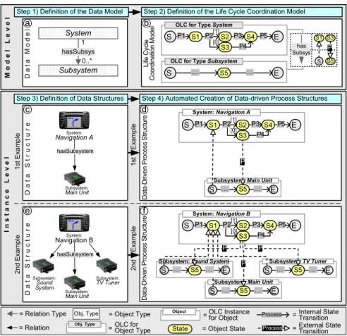
Fig. 1.Creation of Data-Driven Process Structures
Modeling OLCs for hundreds of objects (cf. Example 1) and linking them manually would be too expensive. Therefore, COREPRO follows a model-driven (respectively data-driven) approach by differing between model and instance level. First, for objects with same behavior, we model only one OLC. This OLC can be instantiated multiple times. Second, we utilize the close relationship be- tween data and process structure when connecting different OLCs. Our case studies have shown that semantic relations between data objects can be mapped to dependencies between particular states of OLCs. Based on object (types) and relations between them, process structures can be specified at model level and then be automatically instantiated for every given data structure [2].
2.1 Defining Object Types and Object Life Cycles
Fig. 1 shows the steps necessary to model and instantiate both data and process structures. Steps 1 + 2 deal with the creation of the model level, Step 3 + 4 with the definition of the instance level. Step 1 is related to the specification of the
data model, which defines object and relation types, and therefore constitutes the schema for instantiating concrete (product) data structures. In our context, an object type represents a class of objects within the data model (cf. Fig. 1a), which then can be instantiated multiples times. Fig. 1e shows a data structure which comprises one instance of typeSystemand three instances of typeSubsystem.
Step 2 is related to the modeling of object life cycles (OLC) and their depen- dencies. An OLC defines the states through which objects of the respective type go during their life time. To capture the dynamic aspects of subsystems like TV tuner and Sound System, the process designer models only one OLC for the object typeSubsystem. COREPRO maps OLCs tostate transition systems whose states correspond to object states and whose (internal) state transitions are associated with object-related processes. A state transition does not fire im- mediately when its source state becomes activated, but waits until its associated process has completed. In Fig. 1b, for example, the OLC for object typeSystem starts with initial stateS, then passes stateS1followed byS2orS3, and finally completes in stateE. Theinternal state transitionfromStoS1takes place when finishing processP1. Note that the procedures for modifying the different objects might slightly differ (e.g., different testing procedures forSound SystemandTV Tuner). If the OLCs are identical for such objects, this behavior can be realized as variants within the processes to be executed. Non-deterministic state tran- sitions are realized by associating different internal state transitions with same source state and process, and by adding a process result as condition (e.g.,P2in Fig. 1b). This is required, for example, when associating a testing process with a component, which completes either with result correct or faulty. Depending on the process result, exactly one internal state transition is chosen and its tar- get state becomes activated (cf.S2andS3in Fig. 1b). The other internal state transitions are disabled (cf. Sect. 3).
2.2 Modeling Object Relations and OLC dependencies
Defining the dynamic behavior for each object type by modeling its OLC is only half of the story. We also have to deal with the state dependencies existing between the OLCs of different objects types (cf. Example 1). In COREPRO, an OLC dependency is expressed byexternal state transitionsbetween concurrently enacted OLCs. Like an internal state transition within an OLC, an external state transition can be associated with the enactment of a process; i.e., we do not only support event-based synchronizations, but also allow for the enactment of a transition process (e.g.,send emailorinstall). Regarding the two OLCs modeled in Step 2 from Fig. 1b, for example, we associate the external state transition between state S3(of the OLC for typeSystem) and state S5(of the OLC for type Subsystem) with process P. To benefit from the strong linkage between object relations and OLC dependencies, external state transitions are mapped to object relation types. Regarding our example, the aforementioned external state transition is linked to thehasSubSysrelation connecting the two object types Systemand Subsystem. This information can later be utilized for automatically creating process structures out of given data structures.
The OLCs of all object types and the external state transitions of all relation types form the Life Cycle Coordination Model (LCM) (cf. Fig. 1b). The LCM describes the dynamic aspects of the data model and constitutes the scheme for creating data-driven process structures. This is a unique characteristic of COREPRO allowing for the data-driven configuration of process structures. In particular, different process structures (cf. Fig. 1d and Fig. 1f) can be automat- ically created by instantiating respective data structures (cf. Example 2).
2.3 Generating Data-driven Process Structures
Picking up the scenario from Example 2, COREPRO allows to instantiate dif- ferent data structures (cf. Fig. 1c and 1e) and to automatically create related process structures (cf. Fig. 1d and 1f). A data-driven process structure includes an OLC instance for every object from the data structure. This can be seen in Fig. 1e (data structure) and Fig. 1f (related process structure) where the numbers of objects and OLC instances correspond to each other. Likewise, as specified in the LCM, for each relation in the data structure external state transitions are inserted into the process structure; e.g., for everyhasSubsystemrelation in the data structure from Fig. 1e, associated external state transitions (with process P) are inserted. As result we obtain an instantiated executable process structure describing the dynamic aspects of the given data structure (cf. Fig. 1d and 1f).
To ensure a correct dynamic behavior, created process structures must be sound. A process structure is considered as being sound iff it always terminates properly [3]. Termination of the process structure will be guaranteed if every OLC is sound and there are no cycles caused by external state transitions. An OLC, in turn, is sound (1) if every state can be activated by firing a sequence of state transitions beginning with the start state of the OLC and (2) if the end state of the OLC can be activated by firing a sequence of state transitions beginning from every state within the OLC; further, no state transition must be processing when reaching the OLC end state (i.e., no process is running). It is important to mention that COREPRO allows for checking soundness on model level, i.e., we can ensure that each process structure derived from a sound LCM is sound as well [2]. Thereby, efforts for soundness checks do not rise with the size of the instantiated process structure but only depend on the size of the LCM.
3 Dynamic Behavior of Data-driven Process Structures
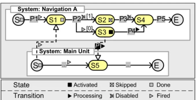
To correctly enact data-driven process structures, a precise and formal opera- tional semantics is needed. This is also fundamental with respect to the analysis of the correctness and consistency of process structures when dynamically chang- ing them (cf. Sect. 4). Therefore, COREPRO uses different markings to reflect the runtime status of an enacted process structure. We annotate both, states and (internal as well as external) state transitions with respective markings each of them representing their current runtime status. Fig. 2 shows an example where markings describe a possible runtime status of the process structure depicted
S P1 S1 S2 P3 E
System: Navigation A
S3 P2
P4 [1]
[0]
S4 P5
S ... S5 E
System: Main Unit
...
P
Disabled
Done Fired State
Transition
Skipped Processing
Activated
Fig. 2.Process Structure from Fig. 1d with Markings During Runtime
in Fig. 1d. By analyzing the state markings from Fig. 2, we can immediately figure out whether a particular state of a process structure has been already passed (e.g., state S1), is currently activated (e.g., state S3), has been skipped (e.g., state S2), or has not been reached yet (e.g., state S4). Transition mark- ings, in turn, indicate whether the associated process has been started, skipped or completed. As we will see later, the use of markings eases consistency checks and status adaptations in the context of dynamic changes of process structures significantly. Therefore, markings of passed regions are preserved during runtime.
Altogether, the runtime status of a process structure is determined by the current markings of its constituent OLCs and (external) state transitions. We first introduce the operational semantics of single OLCs and then the one of the external state transitions needed to synchronize the different OLCs.
3.1 Operational Semantics of Single OLCs
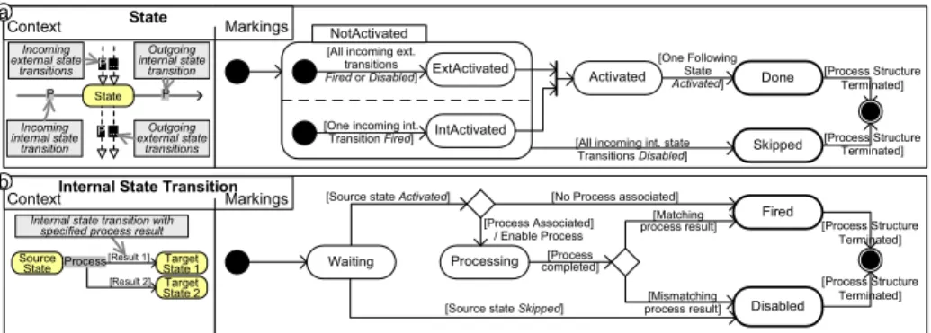
Each state of an (instantiated) OLC has one of the markings NotActivated, Activated, Skipped, or Done. Fig. 3a shows the conditions for setting these markings. Initial marking of a state isNotActivated. An OLC state becomes ac- tivated after one incoming internal state transition has fired and all external state transitions are either fired or disabled. To realize this, marking NotActivated is subdivided into IntActivated and ExtActivated (cf. Fig. 3a). A state will becomeActivatedif both submarkings,IntActivatedand ExtActivatedare reached. At the same time, the preceding state within the OLC is set toDone.
This excludes concurrently activated states within a single OLC.
The dynamic behavior of OLCs is governed by internal state transitions. An internal state transition enters marking Processing and its associated process is started, when the marking of its source state switches toActivated(cf. Fig.
3b). When the associated process completes, the marking of the internal state transition either turns toFiredorDisableddepending on the result of the pro- cess (cf. Sect. 2.1). At the same time, the target state of the respective transition enters submarkingIntActivated(cf. Fig. 3a).
When a transition is disabled, deadpath elimination takes place. Its target state is skipped, and succeeding internal state transitions are disabled as well.
[One Following State Activated] Done
Skipped
[Process Structure Terminated]
[Process Structure Terminated]
[Matching process result]
[Source state Activated]
Waiting
Fired
Disabled [Source state Skipped] [Mismatching
process result]
[Process Structure Terminated]
Processing
[No Process associated]
[Process completed]
Activated NotActivated
[All incoming ext.
transitions
Fired or Disabled] ExtActivated
[One incoming int.
Transition Fired] IntActivated
[All incoming int. state Transitions Disabled]
[Process Structure Terminated]
[Process Associated]
/ Enable Process Source
State
[Result 1]
Process Target
State 1 Target State 2 [Result 2]
P State P
...
...
State
Internal State Transition Outgoing external state
transitions P
P
Outgoing internal state
transition
Incoming internal state
transition
Internal state transition with specified process result
Context Markings
Context Markings
Incoming external state
transitions
a
b
Fig. 3.Behavior of Object States and Internal State Transitions in OLCs
This is continued until the end of the dead path is reached; i.e., until a state is reached which has at least one incoming internal state transition not marked as Disabled(cf. Fig. 3b). Deadpath elimination contributes to avoid deadlocks caused by external state transitions which are waiting for activation (cf. Fig. 2, external state transition with process P). The described OLC semantics has to be extended in conjunction with loops. Due to lack of space, however, we cannot treat loop backs in this paper.
3.2 Synchronization of OLCs
As mentioned, concurrent processing of objects is a fundamental requirement in engineering processes. At the level of a single OLC, concurrency is encapsulated within the transition processes (e.g., implemented in a workflow management or a product data management system). The proper synchronization of concurrently enacted processes within different OLCs is based on external state transitions.
According to internal state transitions, external state transitions are marked as Processing (i.e., their processes are started) when their source state becomes Activated (cf. Fig. 3 and Fig. 4). When the associated process is completed, in turn, the external state transition is marked as Fired. The target state of the fired transition can only become Activatedif one of its incoming internal transitions has already been marked asFiredand all external state transitions are marked either asFiredor Disabled(cf. Fig. 3a and Fig. 4).
[Source state Activated]
Waiting
Fired
[Process Structure Terminated]
[Process completed]
Processing
[No Process associated]
Disabled [Source state Skipped or target state Skipped]
[Process Structure Terminated]
[Target state Skipped]
/ Terminate Process [Process associated]
/ Enable Process Source
State
Target State
External State Transition
OLC A
OLC B
P External state transition
... ...
... ...
Context Markings
Fig. 4.Dynamic Behavior of External State Transitions Between OLCs
External state transitions whose source state isSkippedbecomeDisabled.
Otherwise the external state transition would remain marked asWaitingwhich could lead to a deadlock within its target OLC. Note that a disabled external state transition does not cause any state change within its source or target state.
An external state transitions whose target state becomes Skipped, has to be Disabledas well. First, the external state transition does not influence the target state because it has already been Skipped. Second, we have to ensure proper termination of the process structure. It terminates after all OLCs have reached their end states (cf. Section 2.3). In particular, soundness necessitates that no constituent process is running (i.e., no transition is processing) then (cf.
Sect. 2.3). Therefore, we have to avoid external state transitions whose processes might still be enacted while their target OLC have already reached the end state.
4 Changing Data-driven Process Structures
So far, we have investigated the modeling, instantiation and enactment of data- driven process structures. To cope with the flexibility requirements of engineering processes, we further have to look at dynamic process structure changes.
Example 3 The creation, testing and release of the electrical system of a car takes up to several weeks. Meanwhile, changes of the electrical system, such as the addition of new objects to the electrical system, occur often (e.g., adding a new TV Tuner subsystem to the data structure from Fig. 1c). Consequently, the related process structure needs to be adapted (cf. Fig. 1d); i.e., we have to add the processes (e.g., testing) for the new component to the process structure and must synchronize them with the processes of the already existing components.
Directly changing the process structure would not be a good solution due its size and complexity. Instead, users (e.g., engineers) must be able to perform the changes at a high level of abstraction. In COREPRO this is accomplished by adapting the respective data structure (e.g., describing the electrical system) and by translating these changes into corresponding adaptations of the process structure. Again we utilize the strong relationship between data and process structure to realize this. Furthermore, dynamic changes must not violate sound- ness of the process structure. To ensure this, we have to constrain changes to certain runtime states (i.e., markings) of the process structure.
First, we provide basic operations for static changes of data as well as pro- cess structures (i.e., we do not take runtime information into account). That includes mechanisms for transforming basic change operations applied to a data structure into corresponding adaptations of the process structure. Second, we define marking-based constraints for these change operations in order to ensure soundness of the modified process structure afterwards.
4.1 Static Changes of Data-driven Process Structures
Basic operations enable the change of existing data and process structures. Con- cerning data structure changes, COREPRO allows to insert objects and object
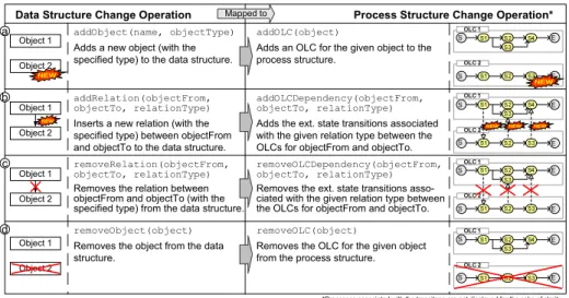
relations into a given data structure as well as to remove them (for an overview see the left-hand side of Fig. 5). The offered set of operations is complete; i.e., it allows the engineer to transfer a given data structure into an arbitrary other data structure, which constitutes an instance of the underlying data model (cf.
Section 2.1). Regarding adaptations of a process structure, COREPRO provides basic operations for inserting and deleting OLC instances as well as OLC instance dependencies (for an overview see the right-hand side of Fig. 5). In particular, we focus on the coordination and synchronization of different OLC instances and do not consider (dynamic) changes of the internal behavior of a single OLC instance. In this paper, we describe only basic operations for adapting data and process structures and omit a discussion on high-level change operations.
As motivated, data structure changes should be automatically transformed into corresponding process structure changes in order to adapt the overall engi- neering process to the new (product) data structure. COREPRO accomplishes this based on the information specified at the model level; i.e., we use the life cycle coordination model (LCM) which defines the OLC for each object type and the OLC dependency for each object relation (cf. Section 2.2 and Fig. 1b).
First, we consider the addition of a new objectx (with typeot) to a given data structure. To realize this change, the addObject operation (cf. Fig. 5a) can be used. This operation, in turn, is translated into anaddOLCoperation (cf.
Fig. 5a) which inserts a corresponding OLC instance to the process structure.
The OLC instance to be added is derived from the OLC linked to object type otwithin the life cycle coordination model (LCM). When adding a new object x to a data structure, its relations to other objects can be specified using the addRelation operation (cf. Fig. 5b). The newly added relations are then auto- matically translated into OLC dependencies of the corresponding process struc- ture. This is realized based on the addOLCDependencyoperation, which inserts corresponding external state transitions between the involved OLC instances.
Again, information from the life cycle coordination model is used to correctly transform the newly added object relation to a corresponding OLC dependency.
To remove an object relationrfrom a data structure, we provide operation removeRelation. It is mapped to operationremoveOLCDependencyfor the pro- cess structure, which removes all external state transitions associated with the relation r (cf. Fig. 5c). Removal of an isolated object (i.e., relations to other objects have been already removed) from a data structure is mapped to the removal of the associated OLC instance from the process structure (cf. Fig. 5d).
4.2 Dynamic Changes of Data-driven Process Structures
As motivated, data-driven process structures have to be dynamically adapted when the related (product) data structure is changed. This section considers dynamic process structure changes and deals with relevant issues.
A key challenge is to preserve soundness of the overall process structure when dynamically adapting it. As long as we only consider static changes (cf. Section 4.1) soundness of an automatically changed process structure can be ensured if the underlying LCM (e.g., Fig. 1b), from which the process structure is derived,
Object 1 Object 2
Object 1 Object 2
Object 1 Object 2
Object 1 Object 2
NEW
addRelation(objectFrom, objectTo, relationType) Inserts a new relation (with the specified type) between objectFrom and objectTo to the data structure.
addObject(name, objectType) Adds a new object (with the specified type) to the data structure.
removeRelation(objectFrom, objectTo, relationType) Removes the relation between objectFrom and objectTo (with the specified type) from the data structure.
removeObject(object) Removes the object from the data structure.
Data Structure Change Operation Process Structure Change Operation*
NEW
NEW NEW NEW
addOLCDependency(objectFrom, objectTo, relationType) Adds the ext. state transitions associated with the given relation type between the OLCs for objectFrom and objectTo.
addOLC(object)
Adds an OLC for the given object to the process structure.
removeOLCDependency(objectFrom, objectTo, relationType) Removes the ext. state transitions asso- ciated with the given relation type between the OLCs for objectFrom and objectTo.
removeOLC(object)
Removes the OLC for the given object from the process structure.
NEW
*Processes associated with the transitons are not displayed for the sake of clarity Mapped to
a
b
c
d
Fig. 5.Data Structure Changes and Related Process Structure Adaptations
is sound. The COREPRO modeling tool always checks this before an LCM can be released. When adapting data and process structures during runtime, we have to define additional constraints with respect to the status of the process structure in order to guarantee soundness afterwards. In particular, the addition or removal of external state transitions must not result in deadlocks or livelocks.
Note that this problem is related to correctness issues discussed in the context of dynamic and adaptive workflows [4, 5]. Here, one has to decide whether a structural change can be applied to a running workflow instance or not. One correctness notion used in this context is compliance [5]. Simply speaking, a workflow instance is compliant with a structurally modified workflow schema if its current execution history is producible on the new workflow schema as well.
In principle, the compliance criterion could be applied to process structures as well. COREPRO logs the events related to the start and completion of the processes coordinated by the process structure in an execution history. However, the compliance criterion is too restrictive for data-driven process structures.
Consider, for example, the dynamic removal of an object from a data structure;
e.g., an already designed component might have to be removed from the elec- trical system when a problem is encountered during testing. Respective runtime changes often become necessary in practice and must be supported, even if the OLC instance related to the data object has been already started or completed (i.e., corresponding entries were created in the execution log of the process struc- ture). For this case, compliance would be violated.
COREPRO uses specific correctness constraints to adequately deal with dy- namic changes. We utilize the trace-oriented markings of OLC states and the semantics of the described change operations when defining these constraints.
First, COREPRO allows to delete an already started or finished OLC in- stanceolc, together with its external state transitions, as long as the execution of other OLC instances has not yet been affected byolc. This constraint will be satisfied if the target states of all outgoing external state transitions of olchave not yet been activated. In particular, this ensures that the removal of olcwill not have any effect on other OLC instances, and therefore does also not influence soundness of the overall process structure. Note that this exactly reflects reality;
i.e., as long as the removal of a data object has no effects on the status of other data objects (i.e., on the states of their related OLC instance) the object and its corresponding OLC (with its external transitions) can be removed.
Second, we constrain the addition of new OLC instances and their depen- dencies to other OLC instances. In particular, it must not be allowed to add an external state transition with the new OLC as source if the target state (of another OLC instance) is already marked as ACTIVATEDor DONE. Otherwise soundness of the overall process structure would be violated. Apart from this, the constraint makes sense from a practical perspective; e.g., it must not be pos- sible to insert untested components into a (product) data structure and relate them to electrical systems which have already been released.
Process structures can become very large. Therefore one goal is to efficiently check whether a dynamic change can be applied to a given process structure. It is important to mention that the operations presented in Sect. 4.1 only modify the process structure itself, but do not affect individual OLC instances (i.e., OLC states and internal state transitions are not changed by these operations).
Furthermore, when analyzing the change scenarios sketched above, we can see that the applicability of a basic runtime change mainly depends on the markings of the target states of the external state transitions to be added or deleted (either explicitly or implicitly due to the deletion or addition of an OLC instance). Thus, we can reduce efforts for constraint checking to the manipulated external state transitions. More precisely, we consider the change regions defined by each of these transitions. Such a region comprises the transition itself as well as its source and target state. In principle, two fundamental issues emerge when dynamically adding or deleting an external state transition:
1. May an external state transition be added or deleted when considering the current marking of the states of its change region?
2. Which marking adaptations become necessary with respect to a change re- gion when adding or removing the respective external state transition?
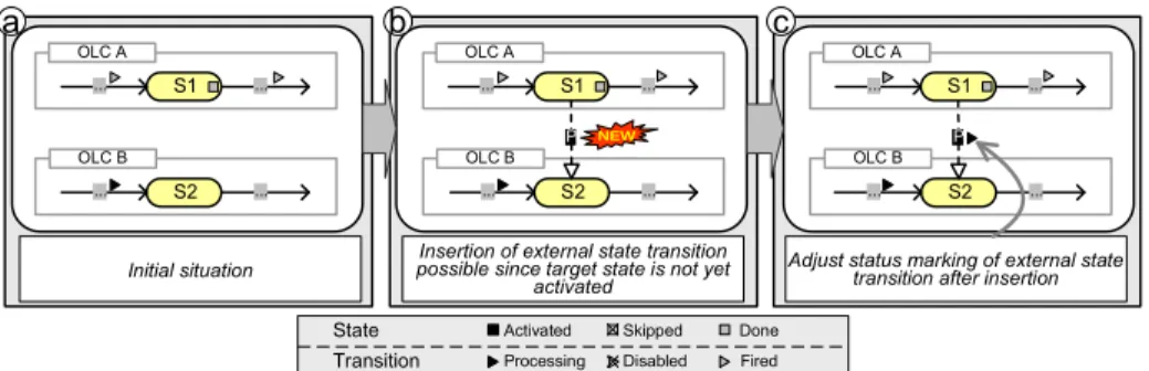
As example consider Fig. 6a which shows two concurrently executed OLC in- stancesOLC A andOLC B. Assume that an external state transition (with asso- ciated processP) shall be dynamically added withS1as source and S2as target state. First, COREPRO checks whether this change is possible considering the current markings of the change region. Since the target stateS2 of the respec- tive external state transition has not yet been activated, the change is allowed (cf. Fig. 6b). When applying it, in addition, the markings of the change region have to be adapted to correctly proceed with the flow of control. In the given example the newly added external state transition is automatically evaluated,
Initial situation OLC B
S2
... ...
OLC A S1
... ...
OLC B S2 ...
P ...
OLC A S1
... ...
a b
OLC B S2 ...
P ...
OLC A S1
... ...
c
Insertion of external state transition possible since target state is not yet
activated
Adjust status marking of external state transition after insertion
NEW
Disabled Done Fired State
Transition
Skipped Processing Activated
Fig. 6.Dynamic Addition of an External State Transition
which changes its marking fromWAITINGtoPROCESSING; i.e., the process related with the transition is instantiated and started (cf. Fig. 6c). Note that a dead- lock would occur in the given scenario if the newly added transition had not been marked asPROCESSING. As another example consider again Fig. 6a. If we tried to add an external state transition with source state S2 and target state S1the change would be not allowed. Otherwise bothOLC AandOLC Bmight be completed before the process associated with the new external state transition completes; i.e., soundness of the resulting process structure would be violated.
Generally, a structure change comprises multiple operations of which either all or none of them have to be applied to the data and process structure. To enable change atomicity and isolation, COREPRO allows to group change op- erations within a change transaction. Removing an object, for example, might require the removal of several relations associated with this object and finally the removal of the object itself. Temporary inconsistencies might occur, but will not become visible to other change transactions and users respectively.
4.3 Practical Impact
In the automotive domain, electrical systems comprise up to 300 components.
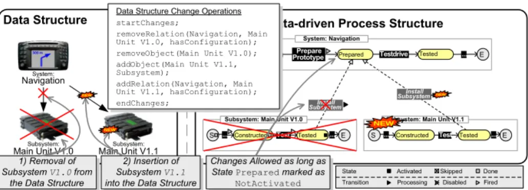
Related process structures have more than 1300 processes and 1500 process de- pendencies [2]. We have already shown the need for dynamically adapting process structures in this scenario. In practice, often more than 50 dynamic changes of a process structure become necessary during its enactment (cf. Example 3). A software error within a component (e.g., the Main Unitof the navigation sys- tem), for example, requires the exchange of this component; i.e., a new version of the component has to be constructed (cf. Fig. 7). When exchanging the compo- nent, the related OLC has to be exchanged as well to ensure that the associated processes can be correctly re-enacted. Whether the adaptation is possible or not depends on the status of the process structure; e.g., if theMain Unitsubsystem has been already installed and the Testdriveprocess has already started, the Main Unitsubsystem must not be exchanged (cf. Fig. 7). COREPRO enables engineers to adapt respective process structures by changing the (product) data structure and by transforming these changes to the process structure.
Data Structure Data-driven Process Structure
S ... Constructed Test E
Subsystem: Main Unit V1.0 Tested ...
Subsystem:
Main Unit V1.1
Subsystem:
Main Unit V1.0
Test
S ... Constructed E
Subsystem: Main Unit V1.1 Tested ...
Install Subsystem
1) Removal of Subsystem V1.0 from
the Data Structure
Install Subsystem
2) Insertion of Subsystem V1.1 into the Data Structure
State Transition System:
Navigation
Testdrive
S Prepare
Prototype System: Navigation
Tested ...
Prepared
Changes Allowed as long as State Prepared marked as
NotActivated
E
NEW NEW
NEW
NEW
Data Structure Change Operations startChanges;
removeRelation(Navigation, Main Unit V1.0, hasConfiguration);
removeObject(Main Unit V1.0);
addObject(Main Unit V1.1, Subsystem);
addRelation(Navigation, Main Unit V1.1, hasConfiguration);
endChanges;
Disabled Done Fired State
Transition
Skipped Processing Activated
Fig. 7.Release Management Process: Creation of a System Release
5 Related Work
At first glance, conventional approaches support modeling and coordination of process structures. Choreography definition languages, for example, allow for the activity-centered specification of the dependencies between (distributed) pro- cesses [6]. Changes of process choreographies are discussed in [7, 8]. The data- driven derivation and change of process structures, however, is not considered.
An approach for enacting and adapting data-driven process structures is pre- sented in [9]. Focus is on simple data structures (e.g., lists, sets). COREPRO, by contrast, enables the definition and change of arbitrary complex data structures as well as automated creation of related process structures. Approaches for de- riving process structures from bills of material are described in [10, 11]. While [10] focuses on product-driven (re-)design of process structures based on design criteria like time or cost, [11] discusses how to coordinate activities based on object relations. The latter approach constitutes the basis of theCase Handling paradigm [12]. The idea is to model a process (structure) by relating activities to the data flow. The concrete activity execution order at runtime then depends on the availability of data. Further approaches providing support for modeling process structures consisting of OLCs are presented in [13, 14]. For example, they enable the generation of activity diagrams from OLCs and vice versa. The generic definition of data-driven process structures as well as their adaptation, however, is not covered by the aforementioned approaches.
There exist approaches from the database area for describing object-oriented data structures and their behavior [15, 16]. They provide a rich set of elements for modeling data structures and for mapping them to OLCs, but neglect en- actment and dynamic changes. COREPRO does not focus on the data modeling part for the following reason. In the engineering domain, data modeling (incl.
the expression of constraints and the avoidance of data inconsistencies) is usu- ally done within a product data management system, which further provides techniques for versioning and variant handling. Our data model constitutes a simplified view on the PDM data model capturing the needs for coordinating and dynamically adapting process structures.
6 Summary and Outlook
IT support for enactment and consistent change of data-driven process structures is a major step towards the use of process management technology in engineering domains. COREPRO provides a new approach with respect to the automated creation and data-driven adaptation of process structures during runtime. In par- ticular, our approach reduces modeling efforts for large process structures and ensures correct coordination of processes. Further, COREPRO enables adapta- tions of process structures at both, build- and runtime at a high level of ab- straction while it disallows dynamic changes of process structures which would lead to an inconsistent runtime situation. Our case studies have shown that in real world scenarios it might be necessary to apply changes even if they lead to inconsistencies. Dealing with such situations requires extensive exception han- dling techniques (e.g., backward jumps within OLCs) which are addressed by COREPRO and will be presented in future publications.
References
1. M¨uller, D., Herbst, J., Hammori, M., Reichert, M.: IT support for release manage- ment processes in the automotive industry. In: BPM. LNCS 4102 (2006) 368–377 2. M¨uller, D., Reichert, M., Herbst, J.: Data-driven modeling and coordination of
large process structures. In: CoopIS’07. LNCS 4803 (2007) 131–147
3. Aalst, W.: Verification of workflow nets. In: ICATPN. LNCS 1248, Springer (1997) 407–426
4. Rinderle, S., Reichert, M., Dadam, P.: Flexible support of team processes by adaptive workflow systems. Distributed & Parallel Databases16(1) (2004) 91–116 5. Rinderle, S., Reichert, M., Dadam, P.: Correctness Criteria For Dynamic Changes
in Workflow Systems: A Survey. DKE50(1) (2004) 9–34 6. W3C: WS-CDL 1.0 (2005)
7. Rinderle, S., Wombacher, A., Reichert, M.: Evolution of process choreographies in DYCHOR. In: CoopIS’06. LNCS 4275 (2006) 273–290
8. Aalst, W., Basten, T.: Inheritance of workflows: an approach to tackling problems related to change. Theoretical Computer Science270(1-2) (2002) 125–203 9. Rinderle, S., Reichert, M.: Data-driven process control and exception handling in
process management systems. In: CAiSE’06. LNCS 4001 (2006) 273–287
10. Reijers, H., Limam, S., Aalst, W.: Product-based workflow design. MIS 20(1) (2003) 229–262
11. Aalst, W.: On the automatic generation of workflow processes based on product structures. Comput. Ind.39(2) (1999) 97–111
12. Aalst, W., Berens, P.J.S.: Beyond workflow management: Product-driven case handling. In: GROUP. (2001) 42–51
13. Liu, R., Bhattacharya, K., Wu, F.Y.: Modeling business contexture and behavior using business artifacts. In: CAiSE. LNCS 4495, Springer (2007) 324–339 14. K¨uster, J.M., Ryndina, K., Gall, H.: Generation of business process models for
object life cycle compliance. In: BPM. LNCS 4714 (2007) 165–181 15. Kappel, G., Schrefl, M.: Object/behavior diagrams. ICDE (1991) 530–539 16. Dori, D.: Object-process methodology as a business-process modelling tool. In:
ECIS. (2000)