Data-driven Modeling and Coordination of Large Process Structures
?Dominic Müller1,2, Manfred Reichert1, and Joachim Herbst2
1 Information Systems Group, University of Twente, The Netherlands {d.mueller, m.u.reichert}@ewi.utwente.nl
2 Dept. GR/EPD, DaimlerChrysler AG Group Research & Advanced Engineering, Germany
joachim.j.herbst@daimlerchrysler.com
Abstract. In the engineering domain, the development of complex prod- ucts (e.g., cars) necessitates the coordination of thousands of (sub-)pro- cesses. One of the biggest challenges for process management systems is to support the modeling, monitoring and maintenance of the many inter- dependencies between these sub-processes. The resulting process struc- tures are large and can be characterized by a strong relationship with the assembly of the product; i.e., the sub-processes to be coordinated can be related to the dierent product components. So far, sub-process coordination has been mainly accomplished manually, resulting in high eorts and inconsistencies. IT support is required to utilize the informa- tion about the product and its structure for deriving, coordinating and maintaining such data-driven process structures. In this paper, we intro- duce the COREPRO framework for the data-driven modeling of large process structures. The approach reduces modeling eorts signicantly and provides mechanisms for maintaining data-driven process structures.
1 Introduction
Enterprises are increasingly demanding IT support for their business processes.
One challenge emerging in this context is to coordinate the execution of large and long-running processes (e.g., related to car development). Engineering processes, for instance, often consist of numerous concurrently executed, interdependent sub-processes. The reasons for this fragmentation are manifold: Typically, these sub-processes are related to dierent (data) objects (e.g., product components), enacted by dierent organizational units (e.g., dealing with the testing or releas- ing of single components), and controlled by dierent IT systems. We denote such correlated sub-processes as process structure.
These process structures have in common that changes (e.g., removing a sub- process or adding a dependency between sub-processes) as well as real-world ex- ceptions (e.g., abnormal termination of a sub-process) occur frequently and may
?This work has been funded by Daimler AG Group Research and has been conducted in the COREPRO (COnguration based RElease PROcesses) project.
aect not only single sub-processes but also the whole process structure [1, 2].
Consequently, IT support must exibly cover modeling, enactment and mainte- nance of process structures and assure their consistency. Even the modeling of process structures constitutes a challenging task since these structures usually comprise hundreds up to thousands of sub-processes (and sub-process depen- dencies). Doing this manually often results in errors or inconsistencies leading to bad process performance and high process costs.
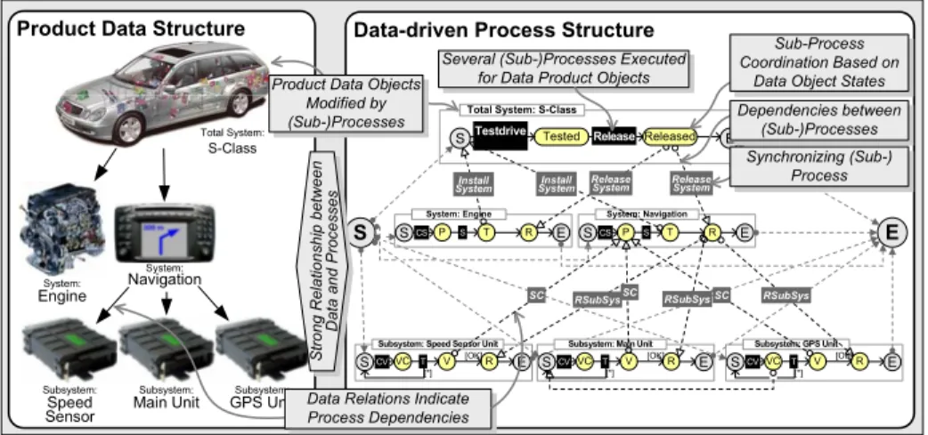
To cope with these challenges, we have to better understand the dependencies between sub-processes. Case studies we conducted in the automotive industry [1, 3] have revealed that the dependencies between the dierent sub-processes of a process structure typically base on the assembly of the product to be man- ufactured. As an example for a product structure (or conguration structure) consider the total electrical system in a modern car which consists of up to 300 interconnected components. To verify the functionality of the total system, sev- eral sub-processes (e.g., testing and release) have to be executed for each electri- cal (sub-)component. Interestingly, the technical relations between the dierent product components indicate sub-process dependencies; i.e., the relation between two components leads to dependencies between sub-processes modifying these components. We use the notion of data-driven process structures to characterize process structures, which are prescribed by respective data structures. Fig. 1 presents an example for a data-driven process structure. The strong relationship between data structures and process structures (e.g., the relations between the S-Class and the Navigation object leads to respective sub-process dependen- cies) also implies that a changed data structure (e.g., total electrical system for another car series without navigation) leads to a dierent process structure.
Our goal is to reduce modeling eorts for data-driven process structures by increasing model reusability and maintainability. In the automotive domain, for instance, we can benet from the upcoming standardization of develop-
Product Data Structure Data-driven Process Structure
Total System:
S-Class
System: Engine
SCS P S E
SCVVC R E
Subsystem: Speed Sensor Unit
T R
V [OK]
T [*]
S
RSubSys Release System Install
System
System: Navigation
SCS P S T R E
SCVVC R E
Subsystem: Main Unit V [OK]
T
[*] SCVVC R E
Subsystem: GPS Unit V [OK]
T [*]
E
Release System Install
System
SC RSubSysSC RSubSys Release
STestdrive Tested E
Total System: S-Class
Released Several (Sub-)Processes Executed
for Data Product Objects
Subsystem:
Speed Sensor
Subsystem:
GPS Unit
System:
Navigation
System:
Engine
Sub-Process Coordination Based on
Data Object States Dependencies between
(Sub-)Processes Synchronizing (Sub-)
Process
Subsystem:
Main Unit Data Relations Indicate Process Dependencies
Strong Relationship between Data and Processes Product Data Objects
Modified by (Sub-)Processes
SC
Fig. 1. Example for a Data Structure and a Related Data-driven Process Structure
ment processes driven by quality frameworks like CMMI (Capability Maturity Model Integration) or engineering guidelines (e.g., [4]). This leads to standard- ized processing of objects (e.g., the testing process for the speed sensor is in- dependent from the car series it is built in), which can be utilized to increase reuse of process models and to reduce modeling eorts. In order to benet from the standardization, a loose coupling of data structures and process structures is required. In particular, three issues arise:
1. How to describe the processing of single objects, i.e., the relationship between an object and its modifying sub-processes?
2. How to describe the processing of the overall data structure, i.e., the depen- dencies between the sub-processes in relation to the dierent data objects?
3. How to automatically derive a proper process structure that can be cus- tomized by the underlying data structure, i.e., dierent data structures lead to dierent process structures?
So far, there exists no IT support for conguring a process structure based on a given data structure. IT systems used in industry, such as product data man- agement systems or workow management tools currently lack an integration of data and processes [1]. Approaches from academia, such as data-centered process paradigms [57] also do not fully address the aforementioned issues. Instead, users have to manually dene the requested process structure for each given data structure. This often leads to inexible process structures and generates high eorts for coordinating and maintaining them. In this paper, we introduce the modeling component of the COREPRO approach, which aims at an intu- itive and product-related integration of data and (sub-)processes. In particular, COREPRO enables
the data-driven specication of process structures at the model level the automated creation of process structures based on given data structures the data-driven adaptation of process structures to deal with real-world
changes.
We utilize the life cycles of objects (i.e., the sequence of states an object goes through during its lifetime) for enabling data-driven modeling and coordina- tion of process structures. State transitions within a life cycle take place when a sub-process is enacted for the related object [811]. According to the rela- tions between objects, we connect the life cycles of these objects. The concept thereby enables the automated derivation of the process structure for a given data structure.
The remainder of this paper is structured as follows: Section 2 character- izes the relationship between data and process structures, and introduces our approach for describing them. Section 3 shows how to model and instantiate (product) data structures. Section 4 deals with the data-driven creation and change of large process structures. Section 5 illustrates the practical benets of the COREPRO approach. Section 6 discusses related work, and Section 7 concludes with a summary and outlook.
2 Overview of the Approach
IT support for the modeling and change of data-driven process structures must meet four major requirements. First, it must enable the denition of the (prod- uct) data structure, i.e., its objects and their relations. Second, with each (data) object a set of sub-processes for processing this object and for transforming its state has to be associated. Third, sub-process dependencies have to be dened based on the object relations. For example, a sub-process for the Navigation object shall be not started before having nished the sub-processes of the re- lated subsystems (cf. Fig. 1). Fourth, the concepts must enable the automated creation of a data-driven process structure.
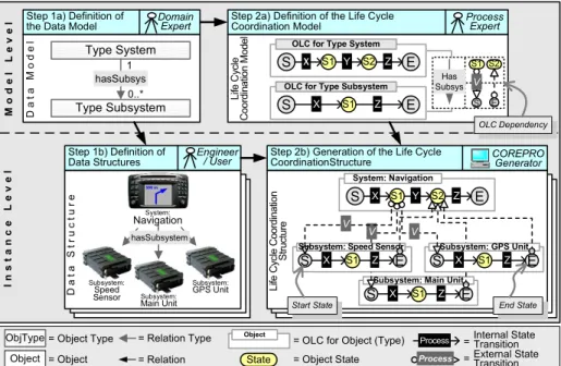
The COREPRO modeling framework meets these requirements. In order to enable reuse and to reduce modeling eorts, COREPRO distinguishes between the model and the instance level when creating data-driven process structures (cf.
Fig. 2). We allow dening a domain specic data model consisting of object and relation types (cf. Step 1a in Fig. 2). Such a data model can then be instantiated to create specic data structures (e.g., a bill of material) consisting of objects and relations (cf. Step 1b in Fig. 2). While the denition of a data model requires profound domain knowledge, the instantiation can be done by users.
Further, process experts describe the dynamic aspects of each object type by modeling object life cycles (OLC). An OLC denes the coordination of sub- processes associated with a particular object type (cf. Step 2a in Fig. 2). A sub- process is an autonomous process (or activity). In COREPRO an OLC is mapped
ModelLevelInstanceLevel
Type System
hasSubsys
Type Subsystem
DataModel Life Cycle Coordination Model
Has Subsys V
S X S1 Y S2 Z E S2 OLC for Type System
S X S1 Z E
OLC for Type Subsystem Step 1a) Definition of
the Data Model Step 2a) Definition of the Life Cycle Coordination Model
DataStructure
Step 1b) Definition of Data Structures
hasSubsystem
Life Cycle Coordination Structure
Step 2b) Generation of the Life Cycle CoordinationStructure
Domain
Expert Process
Expert
Engineer
/ User COREPRO
Generator
S X S1 Z E
Subsystem: Main Unit
S X S1 Z E
Subsystem: GPS Unit
S X S1 Y S2 Z E
System: Navigation
V V
S X S1 Z E
Subsystem: Speed Sensor V
S E
State = Object State
Object
= OLC for Object (Type) Process =Internal State Transition
=
Process External State Transition
= Relation Type ObjType = Object Type
Object = Object = Relation 0..*
1 S1
Start State End State
OLC Dependency
Subsystem:
Speed
Sensor Subsystem:
Main Unit Subsystem:
GPS Unit System:
Navigation
Fig. 2. Overall Concept of the COREPRO Modeling Approach
to a state transition system whose states correspond to object states and whose (internal) state transitions are triggered when associated sub-processes (which are modifying the object) are completed. In Fig. 2, the OLC for object type System (Step 2a), for example, goes through state S1 followed by state S2. The internal state transition from S1 to S2 takes place when nishing sub-process Y.
Altogether, an OLC constitutes an integrated view on a particular object and on the sub-processes manipulating this object.
Dening the dynamic aspects of each object type by modeling its OLC is only half of the story. We also have to deal with the many dependencies existing be- tween the sub-processes associated with dierent objects types. Such dependen- cies might describe, for example, that every system (Engine and Navigation) must have reached a certain state before the Testdrive sub-process for the S-Class can be started (cf. Fig. 1). Consequently, a sub-process dependency can be seen as a synchronization link between the states of concurrently enacted OLCs.
In COREPRO, we specify such sub-process dependencies by dening external state transitions, which connect states of dierent OLCs. Like an internal state transition within an OLC, an external state transition can lead to the enactment of a sub-process. In Fig. 2, for example, the external state transition between the OLCs of Type System and Type Subsystem is associated with sub-process V (cf. Step 2a). Further, external state transitions are mapped to relation types.
In COREPRO, the OLCs for every object type and the external state tran- sitions for every relation type form the Life Cycle Coordination Model (LCM) (cf. Fig. 2, Step 2a). Consequently, the LCM describes the dynamic aspects of the whole data model and constitutes the blueprint for creating the data-driven process structure.
On instance level, the life cycle coordination structure (LCS) describes the process structure for a particular data structure. While data model, data struc- ture, and LCM are created manually, the LCS can be automatically generated based on these ingredients (cf. Step 2b in Fig. 2). The LCS includes an OLC for every object in the data structure. Likewise, for each relation in the data struc- ture, external state transitions are inserted to the LCS. For example, for every hasSubsystem relation in the data structure from Fig. 2 (Step 1b), the associ- ated external state transitions (with the associated sub-process V) are inserted.
The result is an enactable process structure describing the dynamic aspects of the given data structure. Further details are presented in the following sections.
3 Modeling and Instantiation of Data Structures
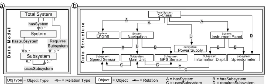
In COREPRO, a domain specic data structure establishes the basis for creating data-driven process structures. COREPRO enables the denition of dynamic aspects of objects and relations at model level. Therefore, the denition of a data model may consist of object and relation types (cf. Fig. 3a). Based on this, data structures can then be created by instantiating specic objects and relations (cf. Fig. 3b).
DataStructure
Total System:
S-Class
System:
Navigation B Subsystem:
Speed Sensor B
System:
Instrument Panel
Subsystem:
GPS Sensor B
Subsystem:
Speedometer B B Subsystem:
Main Unit Information Displ.Subsystem:
D
C C C
C D
A A
System:
Engine A
Subsystem:
Power Supply Total System
hasSystem System
Subsystem hasSubsystem
DataModel
usesSubsystem Requires Subsystem 0..*
1
0..*
1
0..*
1
0..* 0..*
= Relation Type
ObjType = Object Type Object = Object = Relation B = hasSubsystem
D = requiresSubsystem
b a
A = hasSystem C = usesSubsystem
Fig. 3. a) Data Model and b) a Possible Instantiation (Data Structure)
3.1 Creation of a Data Model
Generally, a data meta model provides the constructs for describing a data model [1214]. In COREPRO, we use a simple data meta model, comprising object and relation types1. An object type represents, for example, an abstract or physical product component that is part of the logical structure of a car. A relation type expresses a single relationship between two object types (including cardinality).
A data model comprises object and relation types, and describes how objects are structured in a specic domain (cf. Fig. 3a). Based on the restrictions of the data model, several data structures (i.e., instances of the data model) can be created, such as product structures for dierent car series.
Generally, multiple relation types can be dened between two object types.
Further, we allow dening recursive relation types, which can be used to realize relations between objects of the same object type on instance level.
Denition 1 (Data Model). Let T be the set of all object types and letRbe the set of all relation types. Then: A data model is a tupledm= (OT, RT)where
OT⊆ T comprises a set of object types
RT ⊆ OT × R ×OT comprises a set of binary relation types dened for object types
card : RT 7→ N0×N0 with card(ot1, rt, ot2) = (minrt, maxrt) assigns to each relation typert∈RT a minimal and maximal cardinality.
3.2 Creation of the Data Structure
A data structure contains objects and relations, which constitute instances of the object and relation types dened by the data model. In Fig. 3b, for example, the Total System type is instantiated once, while the System type is instantiated three times (Engine, Navigation, and Instrument Panel). The cardinalities associated with relation types restrict the number of concrete relations between
1 The data meta model neglects descriptive object attributes since they do not inuent the generation of the requested process structure.
objects. Accordingly, a Subsystem object can only be related to one System object via the hasSubsystem relation (cf. Fig. 3b). Note that the data structure from Fig. 3b is a simplied example. In Sect. 5 we indicate, that such a data structure may comprise a high number of instantiated objects in practice.
Denition 2 (Data Structure). Letdm= (OT, RT)be a data model. Then:
A data structure created fromdm is a tupleds= (O, R)with
Ois a set of objects where each objecto∈O is associated with an object type objtype(o)∈OT
R⊆O×RT×Ois a set of object relations meeting the cardinality constraints dened by the data models. Each relation r= (o1, rt, o2)∈R has a relation typert=reltype(r)with (objtype(o1), rt, objtype(o2))∈RT.
4 Integration of Data and Processes
After having dened how a data structure is modeled, we need to specify its rela- tionship to the process structure. To allow for reuse, we describe this relationship at the model level; i.e., we dene the dynamic aspects for the data model and translate them to the instance level afterwards. Therefore, an object life cycle (OLC) describes the dynamic aspects of an object type and an OLC dependency denes the dynamic aspects of a relation type. The life cycle coordination model (LCM) comprises the OLCs for every object type and the OLC dependencies for every relation type. Consequently, the LCM describes the dynamic aspects of the whole data model. On instance level, in turn, the LCM constitutes the basis for creating life cycle coordination structures (LCS) for given data struc- tures. Altogether, the LCS denes the dynamic aspects of the underlying data structure and represents the data-driven process structure.
4.1 Modeling of the Dynamic Aspects of Single Object Types Every object type is associated with an OLC, which constitutes a labeled tran- sition system describing object states and internal state transitions (cf. Fig. 4).
An internal state transition can be associated with a sub-process modifying the object (and thus inducing a state change). This sub-process becomes enacted when the source state of the transition is enabled. After having executed it, the source state of the transition is disabled and the target state becomes enabled.
Hence, the denition of the OLC constitutes the mediator for associating stateful objects with modifying sub-processes2.
To realize non-deterministic processing, the denition of conditional (i.e., non-deterministic) internal state transitions is possible in COREPRO. All internal state transitions with same OLC state as source are associated with the same
2 Stateless objects are also supported. Their OLCs include one internal state transition (with an associated sub-process) from the start to the end state.
S Tested Release E
Total System
Released Faulty
Testdrive[OK]
[*]
State = Object State
Process Internal State Transition with Associated Process
E = Endstate =
S = Startstate
Fig. 4. Object Life Cycle with Conditional State Transitions
sub-process, but can be bound to (dierent) sub-process results, i.e., exit codes (e.g., nished with errors). Depending on the concrete sub-process result, always one internal state transition is triggered at runtime. In Fig. 4, for example, the result of the Testdrive sub-process determines, whether the state Tested or Faulty is enabled. The default transition to state Faulty (indicated by *) be- comes activated in case of uncovered sub-process results. A conditional internal transition may also be used for modeling loops within an OLC.
Denition 3 (Object Life Cycle). Let dm = (OT, RT) be a data model and let ot ∈ OT be an object type. Then: The object life cycle of ot is a tu- ple olc= (P, V, T S)where
P is a set of sub-processes that can be applied to instances of object type ot and V is a set of possible sub-process results (σ:P 7→ P(V)with σ(p)⊆V is the set of possible results dened for sub-process p)
T S= (S, T, sstart, send)is a labeled transition system, where
• S is the set of states that can be reached by objects of type ot
• T ⊆S×(P×V)×S is a set of internal state transitions with
∗ t= (s,(p, v), s0)∈T,⇒v∈σ(p); i.e., a state transition t is triggered by the completion of a sub-process p with particular result v
∗ ∀ti = (si,(pi, vi), s0i) ∈ T, i = 1,2 with t1 6= t2 and s1 = s2,⇒ p1 = p2∧v1 6= v2; i.e., if there are several state transitions with same source state s, all of them will be associated with the same sub- process p. The concrete target state is determined based on the sub- process result. In case of non-deterministic state transitions, there is a default transition that will be chosen if the associated sub-process delivers a result not covered by the other transitions.
• sstart ∈ S is the initial state and send ∈ S is the nal state of the transition system; sstart is the only state without incoming transitions andsend is the only state without outgoing transitions.
Let OLC be the set of all object life cycles. Forolc ∈ OLC, sstart(olc)denotes the start andsend(olc)the end state of the respective transition system.
4.2 Modeling of the Dynamic Aspects of the Data Model
Modeling the dynamic aspects of single object types is only one part of the chal- lenge. To dene the processing of the whole data model, we also have to spec- ify the dynamic aspects of relation types. Relation Types are associated with OLC dependencies which synchronize the OLCs of related objects. An OLC de- pendency comprises several external state transitions between the states of the
dependent OLCs. The resulting structure is denoted as life cycle coordination model (LCM). A LCM describes the dynamic aspects of the data model by inte- grating the OLCs associated with object types as well as the OLC dependencies associated with relation types (Fig. 5a presents the LCM for the data model from Fig. 3a).
Like internal state transitions (within an OLC), an external state transition can be associated with a sub-process. As an example, consider the OLC depen- dency of the relation type hasSystem in Fig. 5a. This dependency consists of two external state transitions, which synchronize (1) the start state of the Total System OLC with the Tested state of the System OLC and (2) the Release state of the System OLC with the Release state of the Total System OLC.
The sub-process associated with the external state transition (e.g., sub-process InstallComponent) can be considered as synchronizing (sub-)process, which op- erates on both related object types.
Denition 4 (OLC Dependency). Let olci = (Pi, Vi, T Si), i = 1,2 be two dierent object life cycles withT Si= (Si, Ti, sstart, send)(cf. Def. 3). Then: An OLC dependency between olc1 andolc2 is a tupleolcDep= (Id, P, EST)where
Idis the identier of the dependency
P is a set of sub-processes that can operate on both object types EST is a set of external state transitions with
est= (s, p, s0)∈EST ⇔(s∈S1∧s0 ∈S2)∨(s0∈S1∧s∈S2).
OLCDEP denotes the set of all OLC dependencies. For an OLC dependency olcDep∈ OLCDEP, letest(olcDep)denote the set of related external state transi- tions.
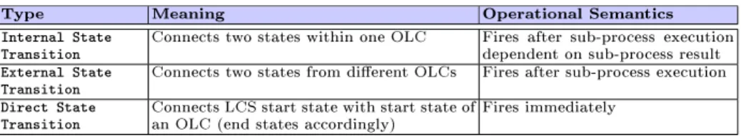
It is important to mention that internal and external state transitions dier in their operational semantics (cf. Table 1). During runtime, the concurrent processing of dierent objects is required to enhance process eciency (e.g., by supporting concurrent engineering techniques). In COREPRO, this is realized by concurrently enacting dierent OLCs while avoiding concurrency within an OLC3. Both, internal and external state transition become activated (i.e., their sub-processes are started) when the source state of the transition is entered.
While the completion of the sub-process of an internal state transition induces
3 Concurrently activated states are not allowed within one OLC since this has not been a requirement in our case studies.
Table 1. Classication of State Transitions in COREPRO
Type Meaning Operational Semantics
Internal State
Transition Connects two states within one OLC Fires after sub-process execution dependent on sub-process result External State
Transition Connects two states from dierent OLCs Fires after sub-process execution Direct State
Transition Connects LCS start state with start state of
an OLC (end states accordingly) Fires immediately
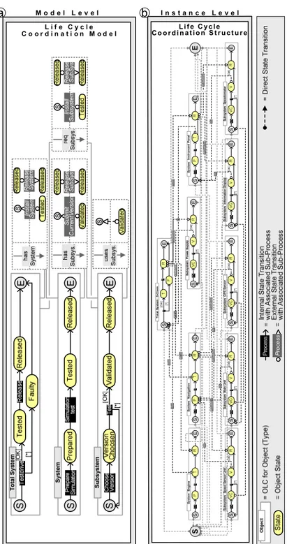
L i f e C y c l e C o o r d i n a t i o n S t r u c t u r e L i f e C y c l e
C o o r d i n a t i o n M o d e l
b
a M o d e l L e v e l I n s t a n c e L e v e l
Fig. 5. Example for a) LCM and b) generated LCS
the deactivation of the source state and the activation of the target state, the completion of the sub-process of an external state transition does not imply any state change in the source OLC.
Further, the target state is activated if and only if the sub-processes of (1) one incoming internal state transition and (2) all incoming external transitions are red. This rule allows for concurrently activated states within dierent OLCs of an LCS, while it prevents concurrently activated states within a single OLC. Due to the lack of space, we omit a formal specication of the operational semantics of internal and external state transtions.
Denition 5 (Life Cycle Coordination Model). Let dm= (OT, RT) be a data model and let P be a set of sub-processes. Then: The life cycle coordination model associated withdmis a tuple lcm= (olc, olcDEP)where
olc:OT 7→ OLC assigns to each object typeot∈OT (of the data model) an object life cycleolc(ot)∈ OLC
olcDEP :RT 7→ OLCDEP assigns to each relation type rt= (ot1, rt, ot2)∈ RT an OLC dependency olcDEP(rt) for the object life cycles olc(ot1) and olc(ot2) of the object typesot1 andot2.
Regarding the execution of created process structures, it is important to guarantee soundness, i.e., to ensure that data-driven process structures termi- nate with a correct end state. Deadlocks might occur (1) when external state transitions are starting from non-deterministic states, and (2) when external state transitions are forming cycles. The rst situation can be avoided during runtime, for example, using deadpath elimination techniques. The second sit- uation can be recognized during buildtime by analyzing the process structure.
Analyzing large data-driven process structures, however, generates high eorts.
COREPRO enables checking soundness on model level and guarantees soundness for every data-driven process structure that bases on a sound LCM.
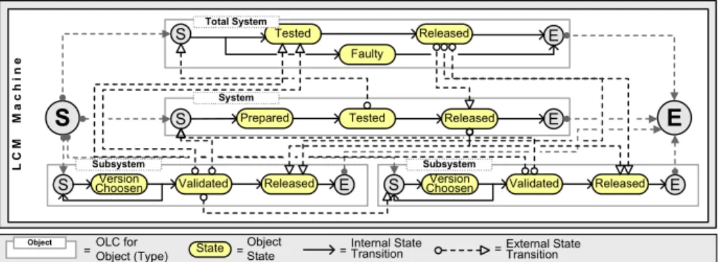
To check soundness of a LCM, all OLCs and OLC dependencies (i.e., their external state transitions) of the LCM are composed. In addition, a unique start state is added and connected with all start states of the OLCs via direct state transitions (cf. Fig. 6). Accordingly, all OLC end states are connected with a unique end state. Direct state transitions are concurrently triggered and lead to the deactivation of the source state and the activation of the target state (cf.
Table 1). We denote the extended transition system resulting from this as LCM machine. The LCM machine constitutes a LCS for a data structure where every element and relation type is instantiated once (to map OLC dependencies for recursive relation types, it is necessary to contemplate two OLCs for the object type associated with the recursive relation type). Thereby, eorts for soundness checks do not rise with the size of the instantiated process structure but only depend on the size of the LCM machine. As example consider Fig. 6, which shows the LCM machine for the LCM depicted in Fig. 5a. Since sub-processes connected with state transitions do not aect soundness checks (we presume sound sub-processes), they can be neglected when analyzing soundness.
LCMMachine
S Tested E
Total System
System
S Prepared E
S ChoosenVersion Released E
Subsystem
Tested Released
Released
Validated
Faulty
S E
S ChoosenVersion Released E
Subsystem
Validated
Object OLC for
Object (Type) = External State Transition
= State Object
State
= = Internal State
Transition
Fig. 6. LCM Machine for the LCM from Fig. 5a
Denition 6 (Soundness of the LCM). A LCM machine is sound if each state of the LCM machine (including its end state) can be enabled by direct or internal state transitions beginning with the start state of the LCM machine and every external transition becomes activated (or deactivated) then.
4.3 Creating the Life Cycle Coordination Structure
So far, we have introduced the data part which comprises the data model and the data structure, and the LCM (consisting of OLCs and OLC dependencies) which integrates the data model and the sub-processes. Based on this, the data- driven process structure, i.e., the life cycle coordination structure (LCS), can be automatically derived for respective data structures. The LCS comprises a start and an end state, an OLC instance for every object in the data structure, and external state transitions between these OLC instances according to the relations dened between the objects (cf. Fig. 5b).
Denition 7 (Life Cycle Coordination Structure). Let dm = (O, R) be a data structure and let lcm= (olc, olcDEP)be a life cycle coordination model.
Then: A life cycle coordination structure based on dm and lcm is a tuple lcs= (olcinst, estinst, sstart, send, ST, ET)where
olcinst:O7→ OLCassigns to each objecto∈O an instance of the associated object life cycleolcinst(o) =olc(objtype(o))
estinst:R7→ OLCDEP assigns to each relationr∈R the associated external state transitionsestinst(r) =est(olcDEP(reltype(r)))
sstart denotes the initial state andsend the nal state
ST is the set of direct state transitions connecting the start state of the LCS with the start states of the instantiated object life cycles
ET is the set of direct state transitions connecting the end states of the instantiated object life cycles with the end state of the LCS.
The operations for creating a LCS are dened in Table 2. Based on a data structure and an LCM, three steps become necessary to generate the LCS. Al- gorithm 1 describes these steps in detail:
1. For every object in the data structure, the OLC associated with the corre- sponding object type is instantiated.
2. For every relation in the data structure, the OLC dependencies associated with the corresponding relation type (i.e., their external state transitions) are inserted to connect states of the dependent OLCs.
3. Direct state transitions are inserted, which connect the LCS start state with all OLC start states and all OLC end states with the LCS end state.
As result, we obtain the complete LCS representing the logical view on the data-driven process structure (cf. Fig. 5b). Such LCS can be transformed to activity-centered process representations, like BPMN or WS-BPEL.
Checking soundness of an LCS comprising hundreds up to thousands of sub-processes and (external) state transitions is a complex task to accomplish.
COREPRO enables soundness checking on model level and ensures that every LCS created on basis of a sound LCM is sound as well (cf. Theorem 1).
Theorem 1 (Soundness of the LCS). Assume that an LCS has been created with Alg. 1 with a particular data structure and an LCM as input. Then: If the LCM machine of the LCM is sound (cf. Denition 6), the created LCS is sound as well.
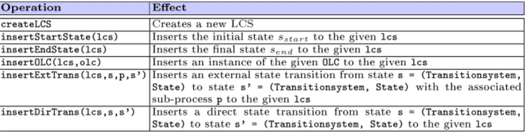
Table 2. Operations for Creating an LCS
Operation Eect
createLCS Creates a new LCS
insertStartState(lcs) Inserts the initial statesstartto the given lcs insertEndState(lcs) Inserts the nal statesendto the given lcs insertOLC(lcs,olc) Inserts an instance of the given OLC to the given lcs
insertExtTrans(lcs,s,p,s') Inserts an external state transition from state s = (Transitionsystem, State) to state s' = (Transitionsystem, State) with the associated sub-process p to the given lcs
insertDirTrans(lcs,s,s') Inserts a direct state transition from state s = (Transitionsystem, State) to state s' = (Transitionsystem, State) to the given lcs
Input:DS= (O, R),LCM= (OLC, OLCDEP) 1 Output:lcs= (OLCinst, ESTinst, sstart, send, ST , ET) 2
// Initialize the LCS and insert start and end state
3 lcs := createLCS; s := insertStartState(lcs); e := insertEndState(lcs);
4
// Insert an OLC instance for every instantiated object and connect it with the start 5 and end state of the LCS via directed state transitions
forallobj∈Odo
6 olc := insertOLC(lcs,olc(objtype(obj)));
7 insertDirTrans(lcs,(lcs, sstart),(olc, sstart(olc)));
8 insertDirTrans(lcs,(olc, send(olc)),(lcs, send));
9
// Insert external state transitions for each instantiated relation 10 forallrel= (o1, rt, o2)∈Rdo
11 // Insert external state transitions between the OLC ofo1 and the OLC of o2 12 forallest= (s1, p, s2)∈olcDEP(rt)do
13 insertExtTrans(lcs,(olcinst(o1), s1), p,(olcinst(o2), s2));
14 return(lcs);
15
Algorithm 1:Generation of the Life Cycle Coordination Structure
Theorem 1 can be inductively proven: The LCM machine constitutes a sound LCS for a data structure where every object type and every relation type are instantiated once. When adding one additional object and all corresponding re- lations to other objects, we can prove that this leads to a sound LCS again (n = 1). Making this assumption for n additional objects, we can show that soundness can still be guaranteed when adding a further object and correspond- ing relations (n→n+ 1). Due to lack of space, we omit further details.
4.4 Change Scenarios
When dealing with data-driven process structures, change management becomes an important issue. Adaptations of process structures become necessary, for ex- ample, when the underlying data structure is changed (e.g., when adding a new object). In COREPRO, such changes can be specied at the data level and are then automatically translated into corresponding adaptations of the process structure. Compared to conventional approaches (e.g., the manual adaptation of activity-centered process structure representations), adaptation eorts can be signicantly reduced. To illustrate this, we sketch three change scenarios in which users (e.g., engineers) adapt the (product) data structure.
Removing an object
Example: The Speed Sensor subsystem shall not be processed any longer, i.e., the Speed Sensor and all its relations to or from other objects are removed from the data structure (cf. Fig. 3b).
Conventional approach: Manually removing associated sub-processes and their incoming and outgoing synchronization links from the process structure.
COREPRO procedure: The corresponding OLC and the external state transitions are automatically removed from the LCS.
Removing a relation
Example: The Main Unit does not use the Speed Sensor any longer, i.e., the relation usesSubsystem between the Main Unit and the Speed Sensor object is removed from the data structure (cf. Fig. 3b).
Conventional approach: Manually removing the sub-process dependencies which are no longer necessary from the process structure (i.e., synchronization links of the sub-processes modifying the Main Unit and the Speed Sensor subsystem).
COREPRO procedure: The corresponding external state transitions are auto- matically removed from the LCS.
Adding an object
Example: A new Head-Up Display subsystem shall be processed as part of the Navigation system, i.e., a new object is added to the data structure and related to the Navigation object (cf. Fig. 3b).
Conventional approach: Manually inserting the corresponding sub-processes and associated synchronization links.
COREPRO procedure: The corresponding OLC and the external state transitions are automatically added to the LCS.
Taking these scenarios, COREPRO allows users to apply process structure changes at a high level of abstraction. Using conventional, activity-driven ap- proaches for process modeling, process structures would have to be manually adapted in case of a data structure change. That requires extensive process knowledge and necessitates additional soundness checks. By contrast, CORE- PRO signicantly reduces eorts for adaptation. The process structure can be adapted without comprehensive process knowledge by simply changing the data structure. The soundness of the resulting process structure is assured, since the model level (i.e., the data model and the LCM) remains unchanged.
5 Practical Impact
To indicate the practical benet of our modeling approach, we introduce a model calculation for a characteristic process from the car development domain: the release management (RLM) process for electrical systems [1, 3]. The calculation (cf. Table 3) bases on the experiences we gained from case studies in this domain.
The release of an electrical system encompasses 200 to 300 components (de- pending on the car series), which are divided in root components and their variants (e.g., driver's airbag as root component and passenger's airbag as its variant). Root components are further divided into categories requiring dierent processing. For example, releasing a multimedia component requires dierent sub-processes when compared to a security related component. Additionally, components are grouped into systems (e.g., navigation system covers several components) to integrate logically coherent components. Finally, systems are collected in total systems, which represent the car series to be developed (e.g., S-Class). Altogether, this leads to the denition of a data model with about 20 object types and 25 relation types connecting them.
On instance level, the relation types with a 1:n cardinality lead to more than 200 instantiated relations. Additionally, there exist dependencies between components that exchange signals and messages. These relation types are dened with an n:m cardinality leading to more than 400 relations. OLCs for the dierent object types coordinate 5 (for components) to 20 (for systems) sub-processes.
In constrast to conventional modeling, the creation of the process structure constitutes an automated task. In total, the LCS contains 200 to 300 OLCs (ac- cording to the number of objects) with more than 1300 sub-processes. Relation types encompass 2 to 6 external state transitions (cf. Table 3) leading to more than 1500 external state transitions within the generated LCS.
The potential for reducing modeling eorts when using the instantiation mechanism of COREPRO depends on the ratio of object types to objects. Even though the calculation bases on a moderate estimate, it indicates that the mod- eling eorts for RLM processes can be signicantly reduced by more than 90%.
The benet even increases considering the fact that soundness checks (cf. Sect.
4.2) and changes (cf. Sect. 4.4) become less complex.
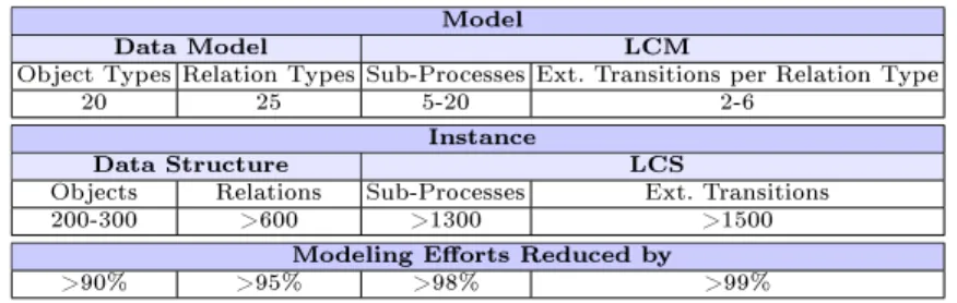
Table 3. Projection of the Modeling Eorts Reduction
Model
Data Model LCM
Object Types Relation Types Sub-Processes Ext. Transitions per Relation Type
20 25 5-20 2-6
Instance
Data Structure LCS
Objects Relations Sub-Processes Ext. Transitions
200-300 >600 >1300 >1500
Modeling Eorts Reduced by
>90% >95% >98% >99%
6 Related Work
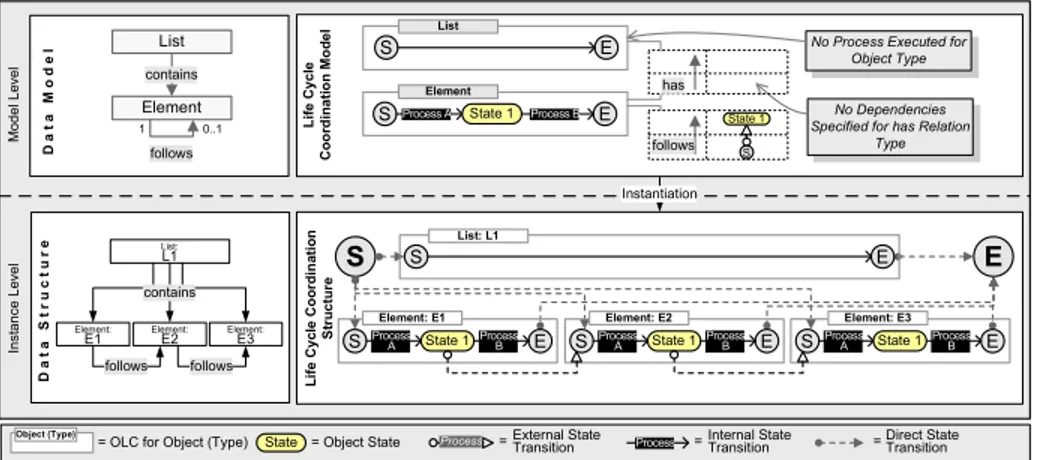
Activity-driven approaches for process modeling do not focus on the automated creation of large process structures comprising multiple sub-processes. Interac- tion graphs [15] and choreography denition languages (e.g., [16]), for example, are activity-centered approaches to specify the choreography between distributed sub-processes. The data-driven derivation of sub-process dependencies is not covered. Other approaches partially enable the data-driven creation of process structures. For example, multiple instantiation of activities based on simple data structures (set, list) [17, 18] is supported by UML 2.0 activity diagrams (Expan- sion Region) [14] and BPMN (Multiple Instances) [19]. They enable iterated or concurrent execution of the same activity for each element given by a at data container. Utilization of respective data structures raises further options, such as data-driven process control with exception handling mechanisms [20]. How- ever, these approaches aim at the sequential or concurrent execution of multiply instantiated activities. COREPRO, by contrast, focuses on the denition of ar- bitrary complex data structures and their association with (sub-)processes. The data-driven process structure in Fig. 7, for example, realizes the interleaved syn- chronization of sub-processes. It represents a list structure where sub-processes are executed for every list element. In this context, COREPRO also allows for the realization of anticipation concepts [21]: Regarding the generated LCS, Process A for Element 2 can be started even though the processing of Element 1 has not been nished.
Approaches for explicitly generating process structures based on bills of ma- terial are described in [5, 7]. The idea of coordinating activities based on data dependencies also constitutes the basis of the Case Handling paradigm [6]. The idea is to model a process structure by relating activities to the data ow. The concrete activity execution order at runtime then depends on the availability of data. Another approach integrating control and data ow is provided by AHEAD [22], which oers dynamic support for (software) development process structures.
The approach enables the integration of control and data ow, by relating ac- tivities to the objects dened in the data model. Based on this information, dynamic task nets are generated. The goal of respective data-driven approaches is the precise mapping of object relations to sub-process dependencies. Though the object relations indicate sub-process dependencies (cf. Sect. 2), the informa-
Instance LevelModel Level
E S
State 1 follows
Instantiation
No Process Executed for Object Type
No Dependencies Specified for has Relation
Type S Process A State 1 Process B E
Element
S E
List
has
State = Object State
Object (Type)
= OLC for Object (Type) = = Direct State
Transition
= Life Cycle Coordination ModelLife Cycle Coordination Structure
Process External State
Transition Process Internal State Transition
S E
List: L1
DataStructure List:
L1
Element:
E1 follows
Element:
E2 Element: E3
follows
S ProcessA Process E
B Element: E1
State 1 S ProcessA Process E
B Element: E2
State 1 S ProcessA Process E
B Element: E3
State 1
DataModel List
contains Element
follows
contains 0..1 1
S
Fig. 7. Interleaved Processing of a List
tion given by relations is insucient for their direct mapping to synchronization edges for three reasons. First, several sub-processes may modify one object, whereas the relation itself does not reect which of these sub-processes have to be synchronized. Second, the relations do not provide sucient information about the direction of synchronization dependencies. In Fig. 1, for example, the relation points from the Speed Sensor to the Navigation object, while the syn- chronization dependencies between their sub-processes point in both directions.
Third, it is also requested to associate synchronization dependencies with the enactment of synchronizing sub-processes (cf. Sect. 4.2).
A general approach following the idea of modeling life cycles and relating them is Object/Behavior Diagrams. The concept allows for the object-oriented denition of data models which can be enhanced by runtime aspects [8]. The behavior is dened for every object within a Petri Net relied life cycle dia- gram. Another approach using life cycles for describing operational semantics of business artifacts (semantic objects) is Operational Specication (OpS) [11].
The collection of all objects and their life cycles species the operational model for the entire business. The Object-Process Methodology (OPM) is an object- oriented approach from the engineering domain. It focuses on connecting ob- jects (or object states) and processes by procedural links [10]. Team Automata provide a formal method to describe the connection of labeled transition sys- tems (automata) via external actions associated with (internal) transitions [9].
Automata including transitions with the same external action perform them si- multaneously. The idea is adopted in [23] where Team-Automata are structured in an object-oriented way. Its synchronization mechanisms are based on events.
These approaches rather focus on an activity-driven specication of dependen- cies (based on events) than on the consideration of data relations for process structure generation. In contrast to event-based synchronization, external state transitions can be added, removed or disabled (e.g., in order to avoid deadlocks) without changing the dynamic aspects of the object itself (i.e., the OLC).
7 Summary and Outlook
The COREPRO approach oers promising perspectives with respect to the modeling and coordination of large data-driven process structures consisting of numerous sub-processes and their interdependencies. COREPRO supports the loose coupling of data and sub-processes by dening life cycles of data objects, and it provides a well-dened mapping of object relations to OLC dependencies.
Further, COREPRO distinguishes between model and instance level, which en- ables a high level of abstraction, extensibility and reuse. In particular, modeling and change eectiveness are signicantly enhanced by
introducing model-driven design in conjunction with an instantiation mech- anism for data-driven process structures
enabling the instantiation of dierent data structures and automatically gen- erating respective data-driven process structures
integrating data and processes which allows users without process knowledge to adapt the process structures by changing the data structure.
Another important issue to be considered is the need for exibility at run- time, such as applying structural changes during enactment (cf. Sect. 4.4). This becomes necessary, for example, when the number of objects or relations be- tween them is not (exactly) known at buildtime. Due to the many sub-process dependencies, uncontrolled runtime changes may lead to inconsistencies not only within single OLCs, but also within the whole LCS. In addition to structural changes, we also have to consider state changes. To realize iterative development processes, for example, data structures need to be processed several times. How- ever, that necessitates the (partial) utilization of previous processing states of objects; i.e., object states which were already activated before execution, have to be retained. For example, product components which have already been tested and which remain unchanged do not need to be tested again. Applying such changes and supporting exceptional situations (e.g., abnormal termination of a sub-process or backward jumps within an OLC) while preserving consistency is a challenging problem [2]. Solutions for runtime scenarios and exception handling are also addressed by COREPRO and will be presented in future publications.
We have implemented major parts of the presented modeling concepts in a prototype, which we use for a rst proof-of-concept case study in car develop- ment [24]. The approach will be applied for modeling, coordinating and main- taining data-driven process structures in the automotive industry. However, the presented concept is not specic to the engineering domain. We also plan to eval- uate COREPRO in the healthcare domain, where the approach shall be used to model medical treatment processes [25].
References
1. Müller, D., Herbst, J., Hammori, M., Reichert, M.: IT support for release manage- ment processes in the automotive industry. In: BPM. LNCS 4102 (2006) 368377
2. Müller, D., Reichert, M., Herbst, J.: Enabling exibility of data-driven process structures. In: Dynamic Process Management. LNCS 4103 (2006) 181192 3. Besteisch, U., Herbst, J., Reichert, M.: Requirememts for the workow-based
support of release management processes in the automotive sector. In: ECEC.
(2005) 130134
4. VDI: VDI Systematic Approach to the Design of Technical Systems and Products.
Beuth Verlag (1987) (VDI Guidelines 2221).
5. Aalst, W.: On the automatic generation of workow processes based on product structures. Comput. Ind. 39(2) (1999) 97111
6. Aalst, W., Berens, P.J.S.: Beyond workow management: Product-driven case handling. In: GROUP. (2001) 4251
7. Reijers, H., Limam, S., Aalst, W.: Product-based workow design. MIS 20(1) (2003) 229262
8. Kappel, G., Schre, M.: Object/behavior diagrams. ICDE (1991) 530539 9. Ellis, C.A.: Team automata for groupware systems. In: GROUP, ACM (1997)
415424
10. Dori, D.: Object-process methodology as a business-process modelling tool. In:
ECIS. (2000)
11. Nigam, A., Caswell, N.S.: Business artifacts: An approach to operational speci- cation. IBM Systems Journal 42(3) (2003) 428445
12. Chen, P.: The entity-relationship model - toward a unied view of data. ACM Transactions on Database Systems 1(1) (1976) 936
13. Jackson, M.A.: Principles of Program Design. Academic Press, London (1975) 14. OMG: UML Superstructure proposal 2.0. (2003)
15. Heinlein, C.: Workow and process synchronization with interaction expressions and graphs. In: ICDE. (2001) 243252
16. W3C: WS-CDL 1.0 (2005)
17. Aalst, W., Hofstede, A., Kiepuszewski, B., Barros, A.P.: Workow patterns. Dis- tributed and Parallel Databases 14(1) (2003) 551
18. Guabtni, A., Charoy, F.: Multiple instantiation in a dynamic workow environ- ment. In: CAiSE. LNCS 3084 (2004) 175188
19. BPMI: Business process modeling notation specication (BPMN) (2006)
20. Rinderle, S., Reichert, M.: Data-driven process control and exception handling in process management systems. In: CAiSE. LNCS 4001 (2006) 273287
21. Grigori, D., Charoy, F., Godart, C.: Coo-ow: A process technology to support cooperative processes. IJSEKE 14(1) (2004) 6178
22. Jäger, D., Schleicher, A., Westfechtel, B.: AHEAD: A graph-based system for modeling and managing development processes. In: AGTIVE. LNCS 1779 (1999) 325339
23. Engels, G., Groenewegen, L.: Towards team-automata-driven object-oriented col- laborative work. LNCS 2300 (2002) 257276
24. Müller, D., Reichert, M., Herbst, J., Poppa, F.: Data-driven design of engineering processes with COREPROM odeler. In: WETICE (ProGility). (2007)
25. Lenz, R., Reichert, M.: IT support for healthcare processes - premises, challenges, perspectives. DKE 61 (2007) 3958