Flexibility of Data-driven Process Structures
?Dominic M¨uller1,2, Manfred Reichert1, and Joachim Herbst2
1 Information Systems Group, University of Twente, The Netherlands {d.mueller|m.u.reichert}@ewi.utwente.nl
2 Dept. REI/ID, DaimlerChrysler AG Research and Technology, Germany joachim.j.herbst@daimlerchrysler.com
Abstract. The coordination of complex process structures is a funda- mental task for enterprises, such as in the automotive industry. Usually, such process structures consist of several (sub-)processes whose execution must be coordinated and synchronized. Effecting this manually is both ineffective and error-prone. However, we can benefit from the fact that these processes are correlated with product structures in many applica- tion domains, such as product engineering. Specifically, we can utilize the assembly of a complex real object, such as a car consisting of different mechanical, electrical or electronic subcomponents. Each sub-component has related design or testing processes, which have to be executed within an overall process structure according to the product structure. Our goal is to enable product-driven (i.e., data-driven) process modeling, execu- tion and adaptation. We show the necessity of considering the product life cycle and the role of processes, which are triggering state transi- tions within the product life cycle. This paper discusses important issues related to the design, enactment and change of data-driven process struc- tures. Our considerations are based on several case studies we conducted for engineering processes in the automotive industry.
1 Introduction
Industry increasingly demands IT support for the coordination of large and com- plex process structures, such as production and development processes. Such structures usually comprise numerous single processes with many interdepen- dencies. Though these dependencies are often domain-specific, there exist gen- eral patterns. Both development and production processes are often structured according to the product, for example a car or an application software suite.
In particular, several single processes have to be executed for every component of the product. Some of The dependencies between the components have to be considered for process coordination. Thus, among other things, the prod- uct structure defines the sequence of process executions. The result is a process structure consisting of interconnected single processes according to the assembly of the product. Usually we use the notion of data-driven process structures for such patterns.
?This work has been funded by DaimlerChrysler Research and Technology and has been conducted in theCOREPRO(Configuration based Release Processes) project
In: Proc. of BPM 2006 International Workshops, Dynamic Process Management (DPM), pp. 179-190. LNCS 4103. Springer Verlag.
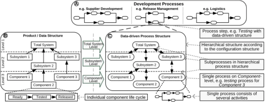
A real world example for data-driven process structures are development processes in the automotive industry. Release management (RLM), for instance, is an important part of the development process for car electrical systems [1].
RLM covers configuration management, testing and release of all electrical com- ponents in a car. Instead of performing RLM processes (e.g., testing) in an iso- lated fashion and solely at the level of single car components (cf. Fig. 1), there is a great need for coordinated execution and synchronization of the results of all RLM processes related to the different sub-components. That means that the processes for single data objects (in our case representing car components) have to be synchronized. Fig. 1 (Box C) shows an example for such a data-driven process structure.
Component 2 Total System
Subsystem 3
Component 1 Component 3
Development Processes
Data-driven Process Structure
e.g. Supplier Development e.g. Release Management e.g. Logistics
Product / Data Structure Total System
Subsystem 1 Subsystem 2
Subsystem 3
Component 1 Component 2
Component 3 Total System
Level
Subsystem Level
Component Level
Subsystem 1 Subsystem 2
Level 1Level 2Level 3
Individual component life cycle
Ready Tested Released
Hierarchical structure according to the configuration structure
Subprocesses in hierarchical process structure Single process on Component-
level, e.g. testing process for Component 3 Single process consists of
several activities Process step, e.g. Testing with
data-driven structure A
B C
Fig. 1.Car development process with a data-driven process structure Currently, the coordination of such data-driven process structures is mainly done manually due to the lack of suitable concepts for automated management.
Except a few approaches [2–7], process design and enactment isactivity-driven in current business process management solutions. Using activity-driven ap- proaches, the connection between data structures and according process struc- tures must be defined manually (i.e., the process structure is modeled according to the data structure). In practice, this leads to inflexible process coordination.
In particular, every change of the data structure necessitates a manual change of the process structure. Regarding usability, an engineer is not interested in changing process models if he or she actually wants to change the product struc- ture. Therefore our goal is to automate the generation and maintenance of these process structures during runtime by following a data-driven approach for their design, enactment and change. However, even modeling is difficult tasks. The information provided by the data structure itself (i.e., the dependencies between the components) is insufficient for the generation of data-driven process struc- tures. On the one hand, it does not include the mapping of the components to processes. On the other hand, the data structures do not imply the control flow between the processes of the resulting structures.
The efficient modeling of process structures also necessitates the considera- tion of domain specific component (i.e., data) states. Possible states are defined by the specific life cycle of the component (cf. Box B in Fig. 1). State transitions
are triggered by executing processes. In the RLM, for example, after executing the testing processes, a state transition fromReady toTested is triggered. The definition of the dependencies between data states and processes is important information for the generation of data-driven process structures.
In this paper, we present the basics for the management of data-driven process structures. We emphasize the core issues for the separation of data struc- ture and process logic in consideration of data states. Based on this separation, we defined example scenarios for possible runtime adaptations of data-driven process structures. The remainder of this paper is structured as follows. Sec- tion 2 describes the modeling of data-driven process structures based on data states while Section 3 describes the enactment of these processes and the role of the data states during execution. Scenarios for flexible process execution are presented in Section 4 and Section 5 discusses the suitability of state-of-the- art approaches for realizing data-driven process structures. The paper concludes with conclusions and an outlook in Section 6.
2 Modeling of Data-driven Process Structures
The idea behind the design and modeling of data-driven process structures is the utilization of data structures as well as data states. Both contribute to cre- ating corresponding process structures and to providing adequate support for their enactment and change. The goal of our data-driven approach is to sustain the separated modeling of data and processlogic. That enables the independent definition of data and processes by domain experts (cf. Fig. 2). As shown in Fig.
2, generating data-driven process structures integrates dataandprocess models.
In particular, the definition of data objects, data states, process templates and process states (Steps 1a to 1d in Fig. 2) constitute prerequisites for the realiza- tion of data-drivenprocess structures. Data objects and data states are defined by data domain experts and represent (real) components. In this paper, we as- sume that the content of data objects does not include information necessary for process execution. Thedata structure itself documents the dependencies be- tween single data objects. With regard to data-driven process structures, the most relevant information about a data object is its state. This state describes the current phase of the object within the object life cycle (OLC) and must be defined in Step 2 (cf. Fig. 2). In the RLM example (cf. Section 1), data objects have the different OLC states termed ready, tested and released (cf. Box B in Fig. 1). Considering the dependencies between data objects, the OLC of a single data object may depend on the life cycle of other data objects. Taking the hier- archical data structure from Box B in Fig. 1, this could mean that a component can be tested only if its sub-components have been successfully tested. Thus, the definition of OLCs depends on the data structure, and it demands the definition of state transitions between single OLCs (cf. Step 3 in Fig. 2).
State transitions within a particular OLC can be realized by the execution of processes which are modifying data objects. The combined application of the OLCs and these processes results in a process structure (cf. Step 4 in Fig. 2).
Data modeler
Step 1a. Define data objects
Process modeler Step 1d. Define
process states
Step 2. Define data structure
Step 3. Define single OLCs
Step 4. Define OLC structure
Step 5. Define process config- uration rules Step 1b. Define
data states
Step 1c. Define process templates
Fig. 2.Necessary steps for modeling data-driven process structures
Clearly, this structure depends on the OLC structure (including all single OLC definitions) and thereby on the data structure.
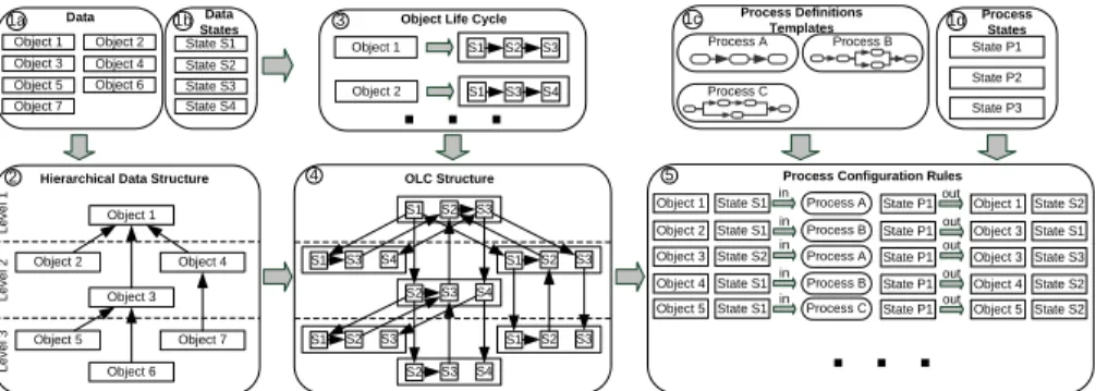
In the following subsections, we describe the necessary steps to realize a data-driven process structure definition. Fig. 3 illustrates the steps described in Fig. 2. The first step consists of the definition of data objects, data states, processes templates and their final states (cf. Boxes 1a-1d in Fig. 3). The second step in modeling data-driven process structures is the definition of the data structure, i.e., the semantic dependencies between data objects (cf. Box 2 in Fig. 3). Generally, these dependencies are hierarchically arranged with every data object having exactly one parent data object. However, these structures often provide many exceptions (e.g., data objects with more than one parent).
For the sake of simplicity, we assume the presence of a hierarchical data structure as used, for example, forbills of material [8].
Process Definitions Templates Process A
Process C
Hierarchical Data Structure
Process States State P1
State P3 State P2 Object Life Cycle
S1 S2 S3
Object 1
S1 S3 S4
Object 2
Object 1
Object 2 Object 3
Object 4
Object 5 Object 6
Object 7
Level 1Level 2Level 3
Process Configuration Rules Object 1 in Process A
State S1 Object 2 State S1 Process B Object 3 State S2 Process A Object 4 State S1 Process B Object 5 State S1 Process C
in in in in
State P1 State P1 State P1 State P1 State P1
Object 1 State S2 Object 3 State S1 Object 3 State S3 Object 4 State S2 Object 5 State S2 out
out out out out OLC Structure
S1 S2 S3
S1 S2 S3 S1 S3 S4
S2 S3 S4
S1 S2 S3 S2 S3 S4 S1 S2 S3 Data
States State S1 State S3 State S2 State S4 Data
Object 1 Object 5 Object 3
Object 2 Object 4 Object 7
Object 6
1a 1b 3 1c 1d
2 4 5
Process B
Fig. 3.Modeling data-driven process structures according to the steps in Fig. 2 Every data object has its own object life cycle, which describes the states (or stages) an object goes through until reaching the desired final state (cf.
Box 3 in Fig. 3). The states are connected by state transitions. Generally, the OLC should not only describe the ideal situation, but also consider exceptional cases (e.g., error states). In addition, OLCs may include hierarchical states, (i.e., with more detailed states). In the RLM, for example, the state Tested includes several substates likeElectrical Check andTest Drive. The aspect of OLCs with hierarchical phases is not discussed in this paper.
Defining OLCs for single data objects is only one part of the challenge. When considering data structures and dependencies between data objects, we also have to deal with dependencies between different OLCs. Box 2 in Fig. 3, for example, depicts a hierarchical data structure including data objects organized at three levels. Based on this data structure, an OLC structure must be also modeled by defining state transitions between different OLCs. As a result, we obtain an OLC structure with defined state dependencies between single OLCs of data objects (Box 4 in Fig. 3).
OLC state transitions represent data object modifications. As mentioned ear- lier, such modifications are accomplished by executing processes. These processes use data objects (in individual states) as input. By executing them, the data ob- jects are modified, and thus their individual states change. These transitions are defined in Box 4 from Fig. 3 in compliance with the OLC structure. As a result, we obtain theprocess configuration describing the structure of the process (cf.
Box 5 in Fig. 3). It is used for generating the control flow of the process structure during runtime. As shown in Fig. 3 (Box 5) we have chosen a simple rule-based representation for the process configuration. Every rule defines an OLC state transition which depends on the current OLC state, the process termination state and the OLC state after process execution. The first rule, for example, triggers the execution ofProcess A whenObject 1 reaches State S1. IfProcess Aterminates in State P1, the state ofObject 1 is changed toS2.
Process templates may be used within several rules. We have simplified mod- eling in this paper - in practice the rules have to be enriched by additional constraints (e.g., time constraints) and processes have more input and output parameters.
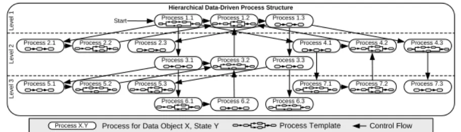
Based on to the process configuration, the control flow of the process struc- ture is generated. Fig. 4 depicts the control flow of the generated process struc- ture. Note that, in practice, these structures become much more complex due to the fact that data structures include more elements than assumed in our examples, and OLCs may consist of numerous phases in practice [1].
Hierarchical Data-Driven Process Structure Process 1.1 Process 1.2 Process 1.3
Process 2.1 Process 2.2 Process 2.3
Process 3.1 Process 3.2 Process 3.3
Process 4.1 Process 4.2 Process 4.3
Process 5.1 Process 5.2 Process 5.3
Process 6.1 Process 6.2 Process 6.3
Process 7.1 Process 7.2 Process 7.3
Level 1Level 2Level 3
Start
Control Flow Process Template
Process X.Y Process for Data Object X, State Y
Fig. 4.Generated process structure
3 Enactment of Data-driven Process Structures
Typically, data-driven process structures are embedded in larger process envi- ronments (e.g., development processes; cf. Box A in Fig. 1) [1]. In our RLM
example, the data-driven process structure is part of the totalRelease Manage- ment process. The execution order of the single processes is controlled by the process structure according to the OLC structure.
The generated process structure (cf. Fig. 4) implies the execution order of the embedded processes. Note that the coordination of the single processes depends directly on the assigned data object states. In the example from Fig. 4, for instance, some processes depend on more than one input object. The top-level processP 1.2, for example, depends on all processes on level 2). We assume an AND-joinfor process synchronization, i.e., the processes of all data objects must terminate before starting execution of ProcessP 1.2.
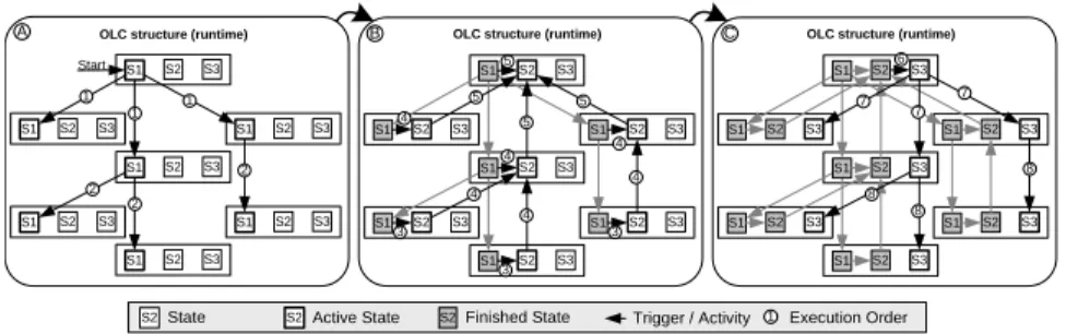
After instantiation of the process structure, all data objects remain in their initial states until modified by corresponding processes. Fig. 5 shows the impact of executing the generated process in Fig. 4 on data states. In Fig. Fig. 5 we have divided this execution in three phases: A, B and C. The execution order of the state transitions (and thus the related processes) is represented by numbered state transitions. Following this approach, the current state of the whole process structure is represented by the state of the top-level data object.
OLC structure (runtime)
S1 S2 S3
S1 S2 S3
S1 S2 S3
S1 S2 S3
S1 S2 S3
S1 S2 S3
S1 S2 S3
1
1 1
2 2 2 Start
OLC structure (runtime)
S1 S2 S3
S1 S2 S3
S1 S2 S3
S1 S2 S3
S1 S2 S3
S1 S2 S3
S1 S2 S3
6
7 7
7
8 8
8 OLC structure (runtime)
S1 S2 S3
S1 S2 S3
S1 S2 S3
S1 S2 S3
S1 S2 S3
S1 S2 S3
S1 S2 S3
3 3
3 4
4 4 5 5 5
4 4
4 5
S2State S2Active State S2Finished State Trigger / Activity 1 Execution Order
A B C
Fig. 5.Process execution order illustrated by state transitions (cf. OLC structure in Box 4 of Fig. 3)
In practice, different processes access and modify data objects. For the gen- eration of the data-driven process structure, that means the current OLC state of a data object may have been already changed before process generation or execution. In the example of RLM, a previously executed instance of the testing process may have modified a component and thus have changed the state of the component toTested. Because of the testing process need to be executed only if the component has been changed, it is not necessary to test it again.
The question is whether the predefined state is subsequently used in another process structure or not. Several points have to be considered in this context.
First, some data objects may be used in different processes, e.g., testing and re- lease. In this context, the predefined state of the data object must be compatible with the OLC structure of the current process configuration to ensure consistent OLCs (i.e., the current data object state has to be used in the current process configuration). Second, predefined OLC states may lead to an inconsistent OLC structure. Fig. 6 depicts such a situation. Box A shows the OLCs of two data
objects (Object 1 and 2) with state transitions between them. The predefined state of Object 2 is S3 (cf. Box B). Box C shows the problem of an undefined behavior caused by the predefined state:Object 1 triggers a state transition to Object 2 and activates a previous state S3. Keeping the predefined state leads to an inconsistent state of the OLC structure up to deadlocks (e.g., state transi- tion from stateS2 ofObject 2 to stateS2 of Object 1). However, resetting the triggered state makes (the advantages of) the predefined state to be lost and induces the re-execution of processes for this object.
Predefined Data State (runtime)
S1 S2 S3
S1 S2 S3
? 1 Execution Order
State Transition S2Predefined State S2State S1Active State Predefined Data State
S1 S2 S3
S1 S2 S3
Predefined Data State (runtime)
S1 S2 S3
S1 S2 S3
A B C
1
Data Object 2Data Object 1
Fig. 6.Behavior during runtime with predefined data states
4 Adaptation of Data-driven Process Structures
In practice, data changes (e.g., removing a component from the product struc- ture) and process changes (e.g., changing the order of different testing processes) occur frequently [1]. Flexibility and dynamic adaptation support are therefore not only required at the level of single process executions, but also at the process structure level. An advantage affected by the modeling method presented in Sec- tion 2 is the ability to adapt data and processes separately. In addition, the data- driven perspective provides a more intuitive view of changes when compared to solely activity-oriented process structures.
To ensure a consistent OLC structure, the applicability of both data and process changes during runtime depends on the current state of the OLC struc- ture (and the process structure respectively). In the following section, we charac- terize possible changes (data structure,object life cycle,object life cycle structure, processes anddata states) and discuss the resulting issues and challenges.
4.1 Data Structure Changes
Modifying data structures (e.g., by adding or removing data objects) during runtime results in several challenges. After updating the data structure, both the OLC structure and the process configuration must be applied correspondingly.
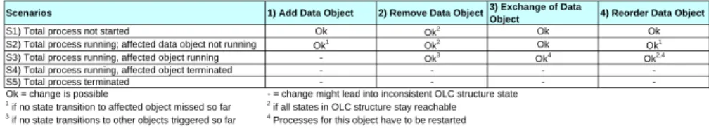
Before modifying a data structure, it must be verified whether this change will lead to a valid result. In hierchical data structures, removing a data object with child-dependenciesclearly also affects its sub-objects. Whether or not the change is possible or requires further operations depends on the state of the affected OLC structure and on the already triggered state changes. Table 1 gives an overview of the data modification scenarios: (1) adding a data object to the data structure;
(2) removing a data object from the data structure; (3) exchanging a data object (and keeping OLC); and (4) moving a data object within the data structure.
Scenarios 1) Add Data Object 2) Remove Data Object3) Exchange of Data
Object 4) Reorder Data Object
S1) Total process not started Ok Ok2 Ok Ok
S2) Total process running; affected data object not running Ok1 Ok2 Ok Ok1
S3) Total process running, affected object running - Ok3 Ok4 Ok2,4
S4) Total process running, affected object terminated - - - -
S5) Total process terminated - - - -
Ok = change is possible - = change might lead into inconsistent OLC structure state 1 if no state transition to affected object missed so far 2 if all states in OLC structure stay reachable 3 if no state transitions to other objects triggered so far 4 Processes for this object have to be restarted
Table 1.Overview of dynamic data changes
Fig. 7 shows the problems we have to deal with when removing a data object (Scenario S4 from Table 1). First, all running processes related to this data ob- ject must be interrupted and terminated in a semantically correct manner (Box A). Second, state dependencies to other data objects (i.e., control flows between processes) must be removed (Box B). Regarding parent data objects this may imply that certain adaptations have to be carried out to preserve consistency. It may be necessary to reset a previous state of the OLC or adding state transitions to prevent unreachable or inconsistent states. In Fig. 7 (Box C), for example, the current state (S3) ofObject 4 is no longer valid whenObject 7 is removed. The active state of Object 4 has to be reset to S2 to prevent inconsistencies. This change also affects other data objects and may necessitate further adaptations of dependent data objects in order to ensure consistent execution of the data-driven process structure. For our example from Fig. 7 this means that the current state (S3) ofObject 1 becomes invalid. However, changing the current state ofObject 1 again results in an inconsistent OLC structure because of further dependen- cies. The state transitions from state S3 of Object 1 to all sub-objects have to be reset. Thus, the whole structure is affected by the initial adaptation.
S2State S2Active State S2Finished State S2 Reset State State Transition 1 Execution Order B
Hierarchical Data Structure Object 1
Object 2 Object 3
Object 4
Object 5 Object 6
Object 7
Level 1Level 2Level 3
S1 S2 S3
S1 S2 S3
S1 S2 S3
S1 S2 S3
S1 S2 S3
S1 S2 S3
S1 S2 S3
OLC structure (runtime) OLC structure (runtime)
S1 S2 S3
S1 S2 S3
S1 S2 S3
S1 S2 S3
S1 S2 S3
S1 S2 S3
S1 S2 S3
2
1 3
A C
Fig. 7.Data structure changes requiring runtime adaptations
4.2 Structural Changes of Object Life Cycles
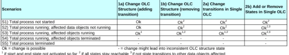
Data structure modifications also affect the OLC structure. For example, adding a new data object may require the insertion of new state transitions to OLCs of dependent data objects as well. Table 2 presents two scenarios for structural changes of OLCs: (1) changes of the OLC structure by itself adding or removing state transitions; and (2) changes of a single OLC.
Clearly, changes of an OLC structure must be done carefully in order to preserve consistency. Adding or removing state transitions, for example, might
Scenarios
1a) Change OLC Structure (adding transition)
1b) Change OLC Structure (removing transition)
2a) Change transitions in Single OLC
2b) Add or Remove States in Single OLC
S1) Total process not started Ok Ok2 Ok2 Ok2
S2) Total process running; affected data objects not running Ok Ok2 Ok2 Ok2,3
S3) Total process running, affected objects running Ok1 Ok1,2 Ok1,2 Ok2,3
S4) Total process running, affected objects terminated - - - -
S5) Total process terminated - - - -
Ok = change is possible - = change might lead into inconsistent OLC structure state 1 if start and end state not activated so far 2 if all states stay reachable 3 if not state transitions to other data objects affected
Table 2.Overview dynamic changes of the OLC structure and single OLCs lead to inconsistent states for OLC structure as well as to violated dependencies.
Fig. 8 (Box A) illustrates the inconsistency that might occur when inserting an additional state transition (cf. Scenario S4 in Table 2). The activation of the new state transition, as shown in Fig. 8 (Box B), leads to an inconsistent state.
One option to deal with this case is to reset the current state of the affected data object. As discussed above, this might again result in an inconsistent OLC structure due to further dependencies.
Single OLC (runtime) OLC Structure
S1 S2 S3 S1 S2 S3
OLC Structure (runtime)
Single OLC
S2 S3
S1 S1 S2 S3
?
S1 S2
Active State State
State Change S2Finished State New transition
A B
C D
S1 S2 S3
S1 S2 S3 S1 S2 S3 S1 S2 S3
?
Fig. 8.Adding state transition to the OLC structure and changing single OLCs Another scenario is the change of a single OLC. As an example, consider the removal of a state from a single OLC for optimization reasons (cf. Fig. 8, Box C). If state changes for this data object have already occurred, consistent OLC operations need to be ensured. Fig. 8 (Box D) shows the problem when changing OLCs during runtime. StateS2 was removed in the OLC definition. If this state is currently activated, the change leads to an inconsistency. A possible solution to deal with this situation is to reset the state of the data object (which may cause further inconsistent states of the whole OLC structure).
4.3 Process Configuration Changes
According to the modeling steps presented in Fig. 2, the changes described in Sections 4.1 and 4.2 affect the process configurations as well (cf. Box 5 in Fig. 3).
However, there are other scenarios for process configuration changes (cf. Table 3). If processes are exchanged in the process configuration, for example, the generated process model must be adapted. Due to the fact that processes have no direct dependencies on other processes themselves (these dependencies are defined by the process configuration), processes are simply exchangeable in our approach - if they are not currently executed (ScenarioS3).
We also have to consider scenarios for already finished processes (Scenarios S4 and S5). In these states, the exchange of a process makes no sense at first glance. However, the process configuration should be updated, because other
reasons may require the re-execution of the process - for example, the external reset of data object states.
Scenarios 1) Exchange Process in Process
Configuration 2) Change Process Template
S1) Total process not started Ok Ok
S2) Total process running; affected process not running Ok Ok
S3) Total process running, affected process running - -
S4) Total process running, affected process terminated Ok Ok
S5) Total process terminated Ok Ok
Table 3.Overview dynamic changes
4.4 External State Changes
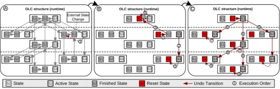
The external change of data object states is typical for development or manu- facturing processes in practice. As example consider a real world failure (e.g., a faulty electrical component) [1] that necessitates a change of the current state of a data object. As discussed earlier, this kind of change may affect the whole OLC structure. Fig. 9 (Box A) shows an example of the external state change of a data object. According to the OLC structure, dependent state transitions must be revoked and OLCs of dependent data objects must be changed. As can be seen from Fig. 9, further data objects have to be involved - even though there is no direct dependency to the initially changed data object. A detailed discussion of this point will be subject of future publications.
OLC structure (runtime) OLC structure (runtime)
S1 S2 S3
S1 S2 S3
S1 S2 S3
S1 S2 S3
S1 S2 S3
S1 S2 S3
S1 S2 S3
OLC structure (runtime)
S1 S2 S3
S1 S2 S3
S1 S2 S3
S1 S2 S3
S1 S2 S3
S1 S2 S3
S1 S2 S3
6 6
7 7
8 8 9
9
S1 S2 S3
S1 S2 S3
S1 S2 S3
S1 S2 S3
S1 S2 S3
S1 S2 S3
S1 S2 S3
2
3 5
S2State S2Active State S2Finished State S2Reset State Undo Tansition 1 Execution Order 1
3 2 4
6
A B C
External State Change
Fig. 9.(External) change of a single data object state and its consequences
5 Related Work
Workflow management systems (WfMS) follow the idea of separating business logic from application code [9]. The resulting workflow specifications can be instantiated and executed during runtime. Several approaches exist for adapting single process instances to handle exceptional situations during runtime [10]. In this paper, we assumed that processes trigger data state transitions. These single processes might be realized as workflows. However, manual mapping of data- driven structures to workflow structures leads to inflexible and large workflow models. The result is a mixture of data structure and process logics, which
increases complexity for execution and maintenance during runtime and is thus not applicable for data-driven process structures.
Data-driven approaches, such asCase Handling[2], provide concepts for flexi- ble process execution based on data dependencies. Activities are linked with data items. The execution order of the activities during runtime depends on the avail- ability of data.Product Driven Case Handling [3] describes the utilization of the case handling approach for product oriented process design. The idea is to model the process according to product characteristics. The advantage of the case han- dling approach is the flexible and efficient execution of processes. Case handling does not explicitly consider data states (i.e., domain specific data states), the definition of hierarchical data structures and the automated generation of data- driven process structures.
Product-driven Workflow Design defines an analytical method for the prod- uct structure based (re-)design of workflows [4]. The idea is to generate a work- flow sequence for producing products based onbills of materialand three design criteria (quality,costs andtime). The goal of this approach is the precise deriva- tion of a process execution sequence according to the product structure. However, we believe that our approach enables a more flexible method for process model- ing. In addition, we focus more on the flexible execution of data driven process based on data state dependencies than on optimization criteria.
The idea ofgoal-based approaches [5] is to generate the process based on a specified initial (and final) condition. Therefore, a task ontology with activities - including data input and output - is defined. The necessary task network is generated (e.g., using planning techniques from artificial intelligence) based on the specified output goal. However, this approach does not deal with the special requirements of data-driven process structures based on data states as well as with flexible runtime adaptations.
There are also similarities of our application when compared to domain spe- cific approaches. A project that considers the requirements of the automotive development processes is WEP [6]. This approach allows for process defini- tion of both structured and unstructured parts. WEP combines WfMS with the goal-based approach. WEP includes also mechanisms for process synchroniza- tion based ondata quality. However, the WEP does not consider the generation process structures according to a data structure.
AHEAD offers dynamic support for (software) development processes [7].
The CoMa product model allows for the definition of configurations, i.e., data structures with dependencies between data objects. The DYNAMITE activity model enables the flexible execution of corresponding processes. Based on the modeled relationships between data and processes, dynamic task nets are gen- erated. Thus, the approach also separates the data structure from the process structure. However, the relevance of data states as well as relationships between data states are not discussed in this approach.
6 Summary and Outlook
The more complex products are the more complex the coordination of related processes becomes. The data-driven generation of these process structures is therefore crucial to their efficient modeling and execution and demands the uti- lization of data structures. as well as support for process enactment and co- ordination. The consideration of (product) data life cycles for the definition of data-driven processes is crucial. In this paper, we have discussed the core chal- lenges of data-driven process structures based on a data state oriented view.
In addition, we have presented the opportunities of the separation of data and process structures for flexible adaptations during runtime.
Further points, such as data flows in data-driven process structures, concur- rently executed processes for one data object (leading to several active states), exception handling (e.g., by using transaction) and the differentiation between changeable and not changeable data states (e.g., physical state Produced) as well as applying the approach for a real world process will be subject of further research in this area.
References
1. M¨uller, D., Herbst, J., Hammori, M., Reichert, M.: IT support for release man- agement processes in the automotive industry. In: BPM. (2006)
2. Aalst, W., Weske, M., Gr¨unbauer, D.: Case handling: A new paradigm for business process support. DKE53(2) (2005) 129–162
3. Aalst, W., Berens, P.J.S.: Beyond workflow management: Product-driven case handling. In: GROUP. (2001) 42–51
4. Reijers, H., Limam, S., Aalst, W.: Product-based workflow design. Management Information Systems20(1) (2003) 229–262
5. Mentink, R., Wijnker, T., Lutters, D., Kals, H.: Supporting manufacturing envi- ronments. (2002)
6. Beuter, T., Dadam, P., Schneider, P.: The WEP model: Adepquate workflow- management for engineering processes. In: ECEC. (1998)
7. J¨ager, D., Schleicher, A., Westfechtel, B.: AHEAD: A graph-based system for modeling and managing development processes. In: AGTIVE. (1999) 325–339 8. Crnkovic, I., Asklund, U., Dahlqvist, A.P.: Implementing and Integrating Prod-
uct Data Management and Software Configuration Management. Artech House Publishers (2003) ISBN 1-58053-498-8.
9. WFMC: Workflow reference model. Technical report, Workflow Management Coalition, Brussels (1994)
10. Reichert, M., Dadam, P.: ADEPTflex: Supporting dynamic changes of workflow without loosing control. JIIS10(2) (1998) 93–129