Instruments of Modern Physics
– A Primer to Lasers, Accelerators, Detectors and all that
Shaukat Khan, TU Dortmund, Summer of 2014
November 12, 2014
Contents
4 Radiation detectors 3
4.1 Interaction of charged particles with matter . . . . 3
4.1.1 Energy loss . . . . 3
4.1.2 Energy straggling . . . . 5
4.1.3 Angular deflection . . . . 6
4.2 Interaction of light with matter . . . . 6
4.2.1 The photoelectric effect . . . . 6
4.2.2 Compton scattering . . . . 7
4.2.3 Pair production . . . . 8
4.3 Interaction of neutral particles with matter . . . . 9
4.3.1 Neutrons . . . . 9
4.3.2 Kaons . . . . 10
4.3.3 Neutrinos . . . . 10
4.4 Gas detectors based on ionization . . . . 11
4.4.1 Gas-filled detector tubes . . . . 11
4.4.2 Multiwire proportional chambers and drift chambers . . . . 12
4.5 Liquid detectors . . . . 14
4.6 Semiconductor detectors . . . . 14
4.6.1 Semiconductor detectors with one readout channel . . . . 15
4.6.2 Semiconductor detectors with spatial resolution . . . . 16
4.7 Detectors based on the photelectric effect . . . . 17
4.7.1 The photomultiplier . . . . 18
4.7.2 The microchannel plate . . . . 19
4.8 Detectors based on scintillation . . . . 19
4.9 Detectors based on Cherenkov and transition radiation . . . . 20
4.10 Detectors for long-wavelength radiation . . . . 21
4 Radiation detectors
Detection of particles or electromagnetic radiation is a central task in modern physics exper- iments. In most cases, the actual detection process involves charged particles producing an electrical signal which is subsequently amplified and digitized. Electromagnetic waves acceler- ate electrons in an antenna or create electron-ion pairs in a gas or an electron-hole pair in a semiconductor. Neutral particles like neutrons or neutrinos are detected by a reaction involving strong or weak interaction, in which charged particles are produced. A few detectors use the heat input from radiation instead of charged particles to produce a signal. Yet another detection mechanism is a chemical reaction e.g. in photographic film emulsion. This chapter is somewhat guided by applications in nuclear and elementary particle physics, which is true for most texts on the subject, e.g. [1, 2, 3]. In the next chapter, however, other detection techniques not fitting in this concept shall be mentioned such as gravitational-wave detectors, atomic-force microscopes and methods used in medical physics (e.g. magnetic resonance imaging).
In any case, it is useful to first consider the fundamental interaction of radiation with matter before plunging into the technical details.
4.1 Interaction of charged particles with matter
4.1.1 Energy lossSeveral processes contribute to the energy lost by a charged particle passing through matter.
•
Multiple inelastic collisions with atomic electrons: For heavy particles (anything heav- ier than electrons or positrons), this is the dominant mechanism, for which a classical derivation was given by N. Bohr.
•
Elastic collisions with atomic nuclei: This process contributes to the energy loss of particles incident on nuclei with comparable mass and is otherwise negligible.
•
Bremsstrahlung: The radiation loss due to deceleration is dominant for electrons and positrons above 10 MeV and is negligible for other particles.
•
Cherenkov radiation: If the kinematic conditions of the collision allow for the emission of real (and not only virtual) photons, energy is lost by electromagnetic radiation. This happens to be the case for particle velocities exceeding the velocity of light in matter
c0=
c/n=
c/√ε, where n
is the index of refraction and
εis the real part of the relative permittivity. Cherenkov radiation is limited to wavelengths at which
ε >1.
•
Transition radiation: Real photons can be emitted at discontinuities of
ε, e.g. at the surfaceof a dielectric material in air or vacuum.
•
Nuclear reactions: At kinetic energies of several MeV, energy loss by nuclear excitation is possible. For energies in the range of 10 MeV and above, nucleons can be liberated.
•
Particle production: At very high energies, new elementary particles (pions etc.) can be created.
While Bohr’s calculation of the energy transferred from incident particles to quasi-free atomic electrons may yield reasonable results for heavy particles at low energy, most cases require a quantum mechanical treatment which results in an approximation known as the Bethe formula
1for the energy loss per path length
dx(also called stopping power):
−dE
dx
= 4π r
e2mec2n z21
β2ln
(
2m
eγ2β2c2 I)
−β2
!
with
re≡ e24πε
0mec2 ,(1) where
reis the classical electron radius,
nis the electron density,
zis the charge number of the incident particles,
βis their velocity in units of
c, γis the corresponding Lorentz factor, and
Iis the mean excitation potential. As a rough approximation,
Iis given by
Z ·10 eV, which results in the so-called Bethe-Bloch formula. A more accurate empirical expression – still ignoring atomic shell effects – is
I ≈Z·(9.76 + 58.8
Z−1.19) eV, which is valid for
Z >13.
As Eq. 1 shows, the loss per unit length decreases with increasing velocity due to the factor 1/β
2, but as
βapproaches unity, there is a slow relativistic rise due to ln
γ2. Particles with kinetic energies of the order of their rest energy are therefore called ”minimum-ionizing particles”. As a charged particle slows down in matter, most energy is deposited towards the end of its path.
This peak of the so-called Bragg curve (dE/dx versus
x) is important in the radiation therapyof cancer since it allows to deliver most of the radiation dose at a desired depth within the body by proper choice of the particle energy.
The Bethe formula can be found with additional terms to Eq. 1, accounting for corrections which depend on the material density and its atomic shell structure, on the internal structure of the incident particles, on higher orders of the scattering cross sections and so on.
For electrons and positrons, the description given by Eq. 1 is rather incomplete for several reasons:
•
Scattering (mainly) from nuclei gives rise to radiation (bremsstrahlung) which dominates the energy loss above a few MeV. Instead of a moderate relativistic rise
∼ln
γ2, the differential energy loss increases linearly with increasing kinetic energy.
1 When comparing the expressions of the Bethe formula from different sources, note that 4 lnx= 2 lnx2 and that the electron density is n =ρNAZ/M, where ρ is the mass density, NA = 6.02·1023/mol is Avogradro’s constant,Zis the atomic number andM is the molar mass in g/mol. Furthermore, the maximum energy transfer is given byWmax≈2meγ2β2c2.
•
To describe the collision losses between electrons/positrons with atomic electrons, the Bethe formula has to be adapted to the respective cross sections which can be calculated within quantum electrodynamics. Examples for distinctly different cross sections are those for scattering between particles without spin (named after Rutherford), between a spin- 1/2 particle and a spin-0 nucleus (Mott), between electron and positron (Bhabha), and between two indistinguishable spin-1/2 particles (Møller).
•
Due to their small mass, electrons and positrons are more likely than other particles to exceed the velocity of light causing Cherenkov radiation or to produce transition radiation.
In both cases, the energy loss is small compared to the collision loss.
A useful quantity is the so-called radiation length, at which the kinetic energy of elec- trons/positrons is reduced by a factor of 1/e due to radiation. Over a wide range of energies, the radiation length
Lris a material-dependent constant. In air, it is about 300 m, in water 36 cm, in metals a few cm or less, decreasing with increasing atomic number (e.g. 8.9 cm for Al, 1.8 cm for Fe, 0.56 cm for Pb, and 0.35 cm for W).
When high-energy electrons/positrons hit matter of sufficient thickness, a so-called electro- magnetic shower is created: the particles emit bremsstrahlung photons, which give rise to the creation of electron-positron pairs; these new particles again emit photons, and so on, until the photon energy is below 1.02 MeV and no new pairs can be created. A new generation of particles and photons is typically created over one radiation length, the maximum of energy loss is at 5 to 6
Lr(implying that too thin shielding can actually increase the radiation dose) and the shower dies out after about 20
Lr.
4.1.2 Energy straggling
Apart from the average energy loss, the distribution of
dE/dxis of interest to understand particle detectors. Since multiple inelastic scattering is a random process, the energy losses are subject to statistical fluctuations giving rise to variations of the signal (in addition to electronic noise) in detectors in which the particles are not completely stopped. This so-called energy straggling depends on the particle velocity and on the material thickness. For thick absorbers with a large number of collisions, the losses approach a normal (Gaussian) distribution. For thin absorbers, the distribution is asymmetric with a pronounced high-energy tail. As an example, one standard deviation from the mean losses of non-relativistic particles passing through a relatively thick absorber is given by
σdE
[MeV] = 0.40
qx[cm]ρ[g/cm3
]
Z/A ,(2)
where
xis the material thickness and the other symbols are the same as before.
4.1.3 Angular deflection
In addition to energy loss, charged particles passing through matter are deflected, which is particularly important for detectors meant to trace back a particle trajectory to its origin (e.g.
to the so-called vertex in collision experiments, at which a particle decayed into other particles).
The deflection is mainly due to elastic scattering (Coulomb scattering) from atomic nuclei.
When passing through a very thin absorber, there may be only one collision and the angular distribution is given by Rutherford’s formula. In many practical cases, however, the detector material is thick enough to allow for a Gaussian approximation of the angular distribution centered at the initial particle direction with a standard deviation of
σθ
[rad] = 20 MeV/c
βp zr x Lr
1 + 1
9 log
10 x Lr
,
(3)
where
zis again the charge number of the incident particle and
pis its momentum.
4.2 Interaction of light with matter
In contrast to charged particles, photons do not lose energy by inelastic collisions, but are either scattered once or a few times or cease to exist due to photoelectric absorption or pair production.
When a photon beam passes through matter, the energy of photons in forward direction is not reduced, but the beam intensity, expressed e.g. by the number of photons per area and time, decreases exponentially according to
I(x) =I
(0) exp(−µx) =
I(0) exp(−µX/ρ),(4) where
µis the absorption coefficient,
ρis the density,
X=
ρxis the area density, and
µ/ρis called mass absorption coefficient, which is connected to the absorption cross section
σvia
µ
ρ
=
σNAM
(5)
with
NAbeing Avogadro’s constant and
Mbeing the molar mass in g/mol. In the following sections, the relevant interaction mechanisms will be briefly discussed.
4.2.1 The photoelectric effect
When a photon of energy
hνis absorbed by an atom, an electron is ejected with a kinetic energy
of
hν−Eb, where
his Planck’s constant,
νis the radiation frequency and
Ebis the binding
energy of the electron. The excited atom decays to a lower state by emitting a fluorescence
photon caused by an outer-shell electron filling the place of the emitted electron. Alternatively,
the energy is transferred to another electron that is ejected, a so-called Auger electron. The
Auger effect is strongly favored for light atoms while fluorescence dominates for atoms with
Z >32. Both, fluorescence photons and Auger electrons are emitted isotropically.
As for the photon absorption, its cross section decreases with increasing photon energy until
hνis sufficient to eject an electron from the next inner shell and the cross section increases at once – this is called an absorption edge. Above the absorption edge, the cross section decreases again (green curve in Fig. 1). The overall decrease of the cross section is roughly proportional to
ν−3, while the decrease is somewhat steeper between the absorption edges. The edge with the highest photon energy is the K edge, at which an electron from the innermost atomic shell is ejected.
Above that edge, the cross section can be calculated using the so-called Born approximation and assuming only K electrons to contribute. Here, the cross section follows
∼Z5ν−7/2. Other parts of the absorption spectrum are more difficult to calculate.
4.2.2 Compton scattering
The scattering process between an incident photon and a quasi-free electron (for not too low photon energy) under observation of energy and momentum conservation is known as Compton scattering. The differential and total cross section of this process is given within the framework of quantum electrodynamics by the Klein-Nishina formula
dσ
dΩ
=
r2e/2(1 + Γ
{1−cos
θ})21 + cos
2θ+ Γ
2(1
−cos
θ)21 + Γ(1
−cos
θ)!
with Γ
≡ hνmec2
(6) and its integration over
dΩ. Here, θis the angle between the incident and outgoing photon.
The low-energy limit of the total cross section is the so-called Thomson cross section
σT= 8π
3
r2e= 6.7
·10
−29m
2= 0.67 barn
,(7) which is far below the photoelectric cross section. Since the Compton cross section decreases slowly with increasing photon energy (blue curve in Fig. 1) while the photoelectric cross section decreases strongly, the two are equal somewhere below 1 MeV.
The Klein-Nishina formula exhibits a forward-backward symmetry in the low-energy limit Γ
→0, while the angular distribution is forward-peaked for higher photon energies.
Since some energy
Tis transfered to the recoil electron, the frequency of the photon is reduced to
ν0 < νafter scattering according to
T
=
h(ν−ν0) =
hνΓ(1
−cos
θ)1 + Γ(1
−cos
θ).(8)
The maximum transferred energy in the case of backscattering (θ =
π) is Tmax=
hν2Γ
1 + 2Γ (9)
and the abrupt end of the electron energy spectrum is known as Compton edge.
Figure 1:
Photabsortion cross sections for lead (Z = 82) as function of photon energy (black curve) with contributions from the photoelectric effect (green), Compton scattering (blue) and pair production (red).Note that the low-energy limit of the Compton cross section is 82·σT.
The total Compton cross section can be subdivided into an incoherent part and a coherent part. The latter, also called Rayleigh scattering, refers to scattering by the atom as a whole during which no energy is transferred to the atom. In the low-energy limit, coherent scattering dominates and its fraction reduces with increasing photon energy.
4.2.3 Pair production
The production of an electron-positron pair is possible for photons exceeding 1.022 MeV, the rest energy of the pair, provided another object (a nucleus) is present to account for momentum conservation. The cross section for pair production increases rapidly with photon energy (red curve in Fig. 1) and is the main contribution to the total cross section above a few MeV.
The electron can escape if created near the surface of the material, the positron most likely annihilates with an atomic electron directly or via positronium formation and leaves two photons or – from ortho-positronium with parallel spins – three photons.
With the decreasing photoelectric and Compton cross section on one hand and the rising
pair production cross section on the other hand, the absorption of photons first decreases with
increasing energy roughly as
ν−3, reaches a minimum at a few MeV and increases again slowly.
4.3 Interaction of neutral particles with matter
Neutral particles living long enough to be detected directly are neutrons (lifetime 880 s), neutral kaons composed of a strange quark/antiquark and a down antiquark/quark (lifetimes 51 ns for
KL0and 90 ps for
KS0), and neutrinos (stable). Their detection requires a strong- or weak- interaction process in which a charged particle is set into motion, either by elastic scattering or by particle creation.
4.3.1 Neutrons
Neutrons interact with the nuclei of matter and are therefore very penetrating. Once they come close to an atomic nucleus, they may
2•
undergo elastic scattering
AZX
N(n, n)
AZX
N,
•
undergo inelastic scattering
AZX
N(n, n
0)
AZX
∗N,
•
perform a nuclear reaction such as
AZX
N(n, p)
Z−1AX
N+1or
AZX
N(n, α)
A−3Z−2X
N−1,
•
be captured under gamma emission
AZX
N(n, γ)
A+1ZX
N+1,
•
initiate a nuclear fission process,
•
produce a hadronic shower.
The cross sections for capture, nuclear reactions and fission are approximately proportional to the inverse velocity (∼ 1/v), inelastic scattering requires neutron energies in the MeV range and the production of hadronic showers, an avalanche-like series of hadronic reactions, requires energies
>100 MeV.
The number of neutrons decreases along the path exponentially (similar to the photon inten- sity)
N(x) =N
(0) exp(−x/λ) with 1
λ
=
σtotρNAM ,
(10)
where
σtotis the total cross section, i.e. the sum of all individual cross sections, and the mean free path
λacts as an inverse absorption coefficient. Note that in this case,
Mis again the molar mass in g/mol (instead of the atomic mass without unit as elsewhere). At low energy, the total cross section is in the region of several barn which is similar to the projected area of a nucleus.
2Here, the usual notation for nuclear reactions will be used: AZXN(a,b)AZYN, where ”X” is the target nuclide,
”a” is the projectile, ”b” is the outgoing particle, and ”Y” is the residual nuclide. Nuclides are labeled by their number of protonsZ and neutronsN and by their massA, an asterix (∗) indicates an excited state, and a dash (as inn0) signifies an inelastically scattered particle.
The trend of
σtot∼1/v is modified by resonances matching discrete nuclear energy levels, but generally a medium-energy neutron is likely to be slowed down (”moderated”) to the ”thermal”
energy range (E
≈kT ≈25 meV) by elastic scattering and will finally be captured or initiate a nuclear reaction. The moderation process is more efficient in light nuclei since more energy is transferred per scattering event. The number
nof such events leading from an initial energy
Eito a final energy
Efcan be shown to follow a simple relation:
n
= 1
ξ(A)
ln
Ei Ef,
(11)
where the so-called lethargy
ξ(A) is a function decreasing with atomic massAwith
ξ(1) = 1for hydrogen and
ξ(12) = 0.16 for carbon, as an example.4.3.2 Kaons
Two neutral kaons are observed, the
KL0(”K-long”) living much longer that the
KS0(”K-short”).
They are mixtures of a
K0and a ¯
K0particle, in which also CP violation plays a role.
When neutral kaons pass through matter, they may undergo elastic scattering like neutrons, or they may give rise to a hadronic shower.
4.3.3 Neutrinos
Neutrinos interact only via the weak interaction which makes them extremely penetrating. Their mean free path decreases with energy being light years at 1 MeV and of the order of the earth’s diameter at 1000 TeV.
Their detection requires a reaction corresponding to the inverse of a nuclear beta decay in the case of electron neutrinos, in which a W boson is exchanged, i.e.
νe
+ n
→e
−+ p and
ν¯
e+ p
→e
++ n (12) or an elastic scattering event, in which a Z boson is exchanged, for example
ν
+ p
→ν+ p or
ν+ e
−→ν+ e
−.(13) The conversion of neutron to proton or vice versa may take place within a nucleus, e.g.
converting
71Ga to
71Ge, which can be detected by chemical means. When a neutrino reaction
sets a charged particle into motion, this particle is usually found by detecting light, either from
scintillation (light emission by excited atoms or molecules) or from the Cherenkov effect. In
either case, due to the rare occurrence of such events, neutrino detectors require a very large
active volume (the IceCube Observatory at the South Pole comprises a volume of 1 km
3) and
have to be well-shielded against other sources of radiation.
4.4 Gas detectors based on ionization
4.4.1 Gas-filled detector tubesA charged particle passing through a gas loses energy due to inelastic scattering and ionization of the gas atoms. If the gas is in an electric field
Eprovided by a capacitor with voltage
U0, the liberated electrons move to the anode and the ions move to the cathode. The anode may be the wire at the center of a gas-filled detector tube, the cathode may be its cylindrical wall, and particles are allowed to enter through a thin window at its end. While
Nelectrons with total charge
N emove towards the anode over a distance ∆z, the change of potential energy
∆V =
N e E∆z = 1
2
C U02−1
2
C(U
0+ ∆U )
2(14)
with
Cbeing the capacitance between anode and ground gives rise to a voltage change ∆U , which can be detected as a current through a resistor. The slower ions induce a lower current signal for a longer period of time.
The typical energy
wrequired to create an electron-ion pair is about 30 eV and does not depend strongly on the particle or gas type. Since this value includes energy losses due to inelastic scattering without ionization, the total number of pairs is simply
N=
W/wwith
Wbeing the total deposited energy. Assuming Poisson statistics to be valid, the relative energy resolution (rms) would be
σW W
=
√ N N
= 1
√N
=
rwW .
(15)
In reality, however, the ionization events are not statistically independent and the resolution is actually better by a factor
√F
, where
Fis the so-called Fano factor:
σW W
=
s F w
W .
(16)
The factor
Fis not easy to calculate, but typical empirical values are around 0.2 for gas detectors.
After the ionization process, electrons and ions have a random velocity given by the Maxwell distribution plus a directional drift velocity depending on the electric field and on the gas pres- sure. This as well as electron-ion recombination, electron capture and avalanche multiplication influences the finally observed signal size and duration. The multiplication effect depends on the voltage between the electrodes. There are three regimes in which a gas detector is typically operated:
•
Ionization chamber: The voltage is high enough to collect all charges at the electrodes but
too low to cause ”secondary” ionization (see next). The signal from an ionization chamber
is rather small and requires a large radiation intensity.
•
Proportional counter: The voltage is high enough to accelerate the electrons such that they ionize the gas atoms with which they collide, and secondary electrons may in turn ionize further atoms leading to an avalanche of up to 10
6times the initial charge. As long as space charge does distort the electric field, the amplified signal is proportional to the initially created charge and this is the typical regime for detectors measuring the deposited energy.
•
Geiger-M¨ uller counter: At still higher voltage, multiple avalanches occur producing a large, saturated signal. A so-called quenching gas is required to prevent a runaway discharge. A Geiger-M¨ uller counter indicates the presence of an ionizing particle but does not yield any energy information.
4.4.2 Multiwire proportional chambers and drift chambers
Single gas counters, as in Fig. 2 (a), are largely replaced by scintillation detectors or semicon- ductor devices discussed below, but they play an important role in particle tracking. Multiple gas-filled tubes (b), one next to the other, can be used if only low spatial resolution is required, e.g. for muon detectors which often form the outermost layer of large detectors in elementary particle research.
Real progress came in the 1960s with the invention of the multiwire proportional chamber (MWPC) which was awarded a Nobel prize (G. Charpak 1992). A MWPC consists of a multitude of anode wires sandwiched between two cathode planes as shown in Fig. 2 (c), which has the same effect as many individual closely-spaced detector tubes allowing to detect multiple particle traces simultaneously with good spatial resolution and a time resolution of a few 10 ns. Instead of wires in one plane, a whole volume can be filled with anode wires surrounded by cathode field wires, as in Fig. 2 (d).
In a so-called drift chamber, the temporal information of the electric pulses is employed to improve the spatial resolution. It takes some time (on the
µs level) until the charge drifts fromits place of creation to a wire. A particle track can be thought of being tangential to circles surrounding each nearby wire, where the circle radius is given by arrival time of the pulse at the readout of the wire.
The construction of a MWPC and drift chambers can be quite artful, aligning many parallel anode wires with a thickness of several 10
µm and a spacing of a few mm. Here, a particularproblem is the curvature caused by the electrostatic repulsion between adjacent wires and their attraction by the cathode planes. The gas is typically a mixture of argon and some other components, e.g. isosbutane (C
3H
8) providing high amplification.
Since a few years, gas microstrip detectors are also in use, in which the wires are replaced by narrow-spaced strips on an insulating substrate, see Fig. 2 (e).
There are several methods to achieve spatial resolution in wire direction. Wires can be read
out at both ends and the fractional charge collected at either end indicates the longitudinal
Figure 2:
Summary of gas ionization detectors, showing a cylindrical counter tube (a), techniques for spatial detection perpendicular to the detector (b)-(e) and along the axis (f)-(i). Spatial resolution in the plane perpendicular to the anode wires is achieved by an array of counters (b), multiple wires between cathode planes (c), multiple wires between cathode field wires (d), or replacing the wires by anode strips (e). Spatial resolution along the wires is obtained by charge-dividing readout (f), segmented cathode planes (g), or tilted wires (h). A time projection chamber (TPC) with anodes at either end of a gas-filled volume with parallel electric and magnetic field is shown in (i).position, as sketched in Fig. 2 (f). For MWPC, the cathode planes can be segmented into strips perpendicular to the wire direction (g). Some drift chambers have ”stereo” wires (h) at an angle with respect to the other wires to yield 3-dimensional information on the particle track.
Another detector using the drift time of charges in a gas is the so-called time projection chamber (TPC) which consists of a large gas-filled cylindrical volume (88 m
3in the case of the ALICE detector at CERN/Geneva) with an electric and a magnetic field, both parallel to its axis. The magnetic field is provided by surrounding coils, the electric field is given by a thin planar electrode at the center, see Fig. 2 (i). In this combined field, electrons perform a spiral motion while drifting to the end caps of the cylinder which consists of a MWPC layer.
The spatial information perpendicular to the chamber axis is given by the spot at which the electrons hit the end cap, the position along the axis is given by the drift time.
Other gas-filled discharge detectors which are not much in use nowadays, such as so-called
streamer chambers, spark chambers and flash chambers, will not be discussed here.
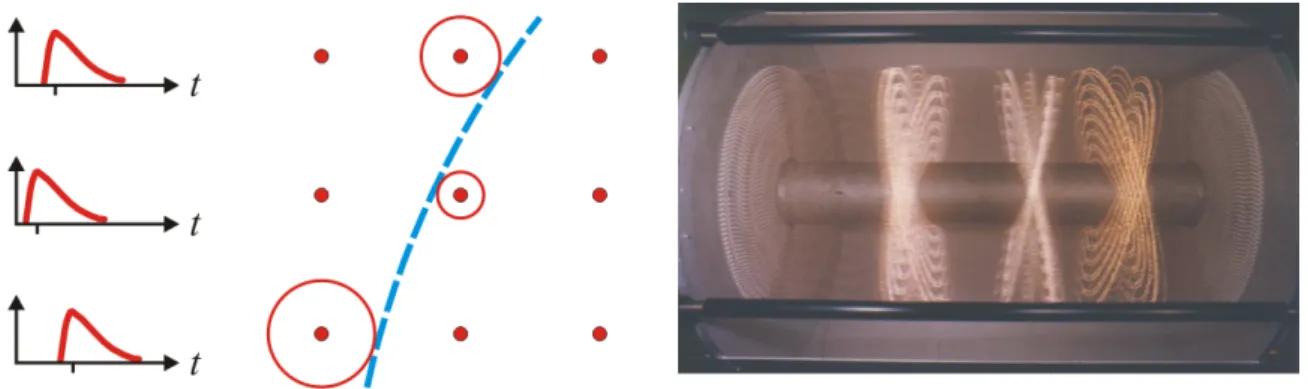
Figure 3:
Principle of the drift chamber: The reconstructed particle track (blue) is tangential to circles surrounding each wire (red) with a radius given by the drift time (left), which can be measured starting from a common trigger signal. Right: The 2 m long drift chamber of the ARGUS experiment, decom- missioned in 1992, with approximately 30000 wires. The size of one ”cell”, consisting of a 30 µm thick sense wire at a potential of about 3000 V surrounded by 76µm thick cathode wires at ground potential, is 18 mm.4.5 Liquid detectors
Liquid ionization detectors offer advantages over gas-filled detectors, notably their much higher density which increases the number of ion-electron pairs
Nin Eq. 15 by three orders of mag- nitude. Compared to
≈30 eV per pair in gas, the required energy is somewhat lower in liquid argon (LAr, 24 eV), liquid krypton (LKr, 20 eV) and liquid xenon (LXe, 16 eV). A particular problem is the required purity of the liquid, and this technical problem has only been mastered for liquid noble gases so far. Given their technical complexity, liquid ionization detectors (LIDs) are not frequently used.
Another liquid-filled detector, the bubble chamber, is mainly of historical interest. Here, a liquid is kept close to its boiling point. For a short period of time, the pressure is reduced by a piston such that the liquid is actually above the boiling point, and bubbles are created in this
”superheated” liquid along the ionization track of a charged particle. The now visible particle trajectory is then imaged by cameras from different angles, which allows a three-dimensional reconstruction even for a large number of simultaneous tracks.
4.6 Semiconductor detectors
A reverse-biased semiconductor diode is a good medium for an ionization detector. The energy
to produce an electron-hole pair is only 3.6 eV in silicon and 2.8 eV in germanium, and due to
the high density (compared to gas-filled detectors), a large number of pairs can be created. The
Fano factor (see Eq. 15) of silicon detectors is around 0.1, they are compact, collect charge on
the ns timescale, and they profit from the silicon technology in several ways (material purity,
miniature segmentation, integration of on-chip readout electronics, etc.).
4.6.1 Semiconductor detectors with one readout channel
Simple detectors without spatial resolution based on silicon or germanium are popular in ra- diometry and nuclear physics. There are a number of designs for different purposes:
•
Diodes with p-n junctions, where ”p” and ”n” refers to the type of impurity with which the semiconductor is doped. Applying a reverse bias (plus connected to n, minus connected to the p) creates a region which is depleted of charge carriers (electrons and ”holes”). A charged particle creates charge carriers which are drawn to opposite sides by the electric field caused by the bias voltage. Diodes with p-n junction are extensively used as photodi- odes to detect light in the near-visible range. Photodiodes have a time resolution scaling with size – the signal from a diode with 100
µm diameter can have a rise time of a few 10ps.
•
Surface-barrier detectors have a semiconductor-metal junction (n-Au or p-Al) which is quite similar to an n-p junction. The semiconductor can be depleted over its whole thick- ness which is required for a reliable measurement of the energy lost by a traversing particle and makes this detector type very attractive for nuclear-physics applications, in which pro- tons or alpha particles are emitted from nuclei.
•
Diodes with p-i-n junctions, where ”i” stands for intrinsic (not or weakly doped) material.
The intrinsic layer increases the depleted thickness
dand reduces noise by decreasing the junction capacitance
εA/d, where εis the permittivity and
Ais the detector area. P-i-n diodes are employed as photodiodes, having a larger bandwidth compared to p-n diodes, but are also used for particle detection.
•
Avalanche photodiodes (APDs) are essentially p-i-n diodes with an additional doped layer modifying the electric field in such a way that a controlled avalanche breakdown of the diode occurs. Not unlike a gas counter in proportional mode, accelerated electrons create secondary charges in an avalanche-like fashion. With a reverse bias above 100 V, amplifi- cation factors of 100 and more are reached, producing sizable signals from initially weak input. With even higher bias, APDs act like Geiger-M¨ uller counters and can be used to detect single photons. An array of APDs in Geiger-M¨ uller mode, the sum signal of which yields phonton intensity information, is sometimes called a ”silicon photomultiplier”.
•
Lithium-drifted detectors like Si(Li) or Ge(Li) are like p-i-n diodes in which the ”i” layer is
not undoped but compensated, i.e. Li atoms are diffused into p-doped material canceling
the doping effect. Si(Li) detectors are used to detect X-rays while Ge(Li) detectors with
Z= 32 (compared to silicon with
Z= 14) and a much higher photoabsorption cross section
are the classical devices to measure gamma-ray spectra. Both detectors must be cooled
with liquid nitrogen to suppress the mobility of the Li atoms. While Si(Li) detectors may be warm for a short time, Ge(Li) detectors are destroyed by warming them up only once.
4.6.2 Semiconductor detectors with spatial resolution
Spatial resolution of a diode-like detector can be achieved with resistive charge division or segmentation. Devices to measure the position of e.g. a laser spot are
•
Position-sensitive diodes (PSDs): A p-i-n diode with two or four readout connections acts as continuous position detector. The difference-over-sum ratio of the signals from two opposite connections is roughly proportional to the position between them.
•
Quadrant diodes: A photodiode divided into a two-dimensional array of four segments acts as a continuous position detector as long as each segment is hit by a fraction of the light pulse.
•
Strip detectors or line cameras: A one-dimensional array of many strip-like segments yields spatial resolution in one direction depending on segmentation pitch
d, i.e. the distancebetween the strip centers. If a signal comes from only one strip, the spatial resolution is given by
d/√12, the rms value of a rectangular distribution. The resolution can be much better for the centroid value if more than one strip is illuminated. One-dimensional line cameras are sufficient for some applications, e.g. to measure the spectrum of light dispersed by a grating.
•
Pixel detectors, particularly CCDs: A large two-dimensional array of segments or ”pixels”
(e.g. 1024 x 1024) yields spatial resolution in two directions depending on the pixel size in either direction (pixels are not necessarily squared). Sophisticated pixel detectors are nowadays used in every amateur camera and even in mobile phones, but there are also scientific applications. In many cases, charge-coupled devices (CCDs) are used to detect near-visible light and in rare cases also particles (if the low readout speed is no factor).
Charge-coupled devices (CCDs) bear more resemblance to field-effect transistors rather than diodes. Each pixel comprises an insulating layer with a doped semiconductor on one side and a metallic electrode on the other side. The semiconductor and electrode are biased such that a depleted region is created in the vicinity of the insulator. If electron-hole pairs are created by incident photons or charged particles, the charge carriers of one polarity are pulled away by the bias while those of the other polarity – unable to pass through the insulating layer – are captured under the electrode. To extract the charge from the pixels, the bias of adjacent pixels can be changed periodically such that the charge is drawn from one electrode to the next ”clocking” the whole charge content of the CCD array line-by-line to a one-dimensional register at one edge.
The charges in the register are then sequentially amplified, converted to a voltage and digitized.
The whole process is rather slow (of the order of milliseconds) compared to the readout of other
detectors, but fast enough for e.g. a video camera with 25 images per second. In high-energy physics, the vertex detector of the SLD detector at the SLAC Linear Collider (SLC) in Menlo Park/USA, operated from 1992 to 1998, could employ CCDs because the repetition rate of the SLAC linac was low enough (120 Hz).
In collider experiments at storage rings, the collision rate is much larger, e.g. 40 MHz at the LHC at CERN, requiring faster detectors. Here, silicon micro-strip detectors are extensively used. A typically 300
µm thick n-doped Si wafer has a conducting layer on one surface, whilethe other surface is covered with p-doped parallel strips with a pitch of 20 to 50
µm. Eachstrip is connected to a charge-sensitive amplifier on an adjacent readout chip (sometimes, only every other strip is connected). Typically, a signal from one particle is obtained on 2 or 3 adjacent strips and the spatial resolution of centroid is a few
µm. Silicon vertex detectors inelementary particle physics usually comprise several layers of micro-strip detectors to trace back each particle track to the vicinity of the collision point. Finding tracks with a common origin (a ”vertex”) can be used to measure the lifetime of a primary particle that moved a certain distance before decaying. Furthermore, knowing which tracks belong to the same decaying particle greatly reduces the combinatorial background from wrongly assigned tracks. When extrapolating tracks to the collision point, the multiple-scattering angular error from Eq. 3 in the silicon layers, in any support structure, and in the vacuum chamber of the collider must be taken into account.
One-dimensional transverse spatial resolution (perpendicular to the colliding-beam axis) is sufficient to assign vertices, if they are transversely displaced, and to measure the particle momentum by the track curvature in a magnetic field parallel to the beam axis. Of course, two- dimensional information would be better. A simple solution with the disadvantage of doubling the amount of matter (and thus increasing the angular error) is to use two detectors with crossed strips, which give a unique answer if not too many tracks intersect the detector simultaneously.
Designing truly two-dimensional pixel detectors with fast readout has been an active field of research for many years, not only for elementary particle physics, but also to record diffraction patterns in synchrotron light sources and FELs and for medical applications. Here, one prob- lem is the readout speed (if all pixels were read out sequentially), the other is the number of connections (if all pixels were read out in parallel). The attempted solutions aim at integrating amplifiers and readout circuitry on the same chip as the pixels, and at inventing ”bonding”
techniques (using small wires or soft metallic bumps) to connect the pixels to the outside world.
4.7 Detectors based on the photelectric effect
The photoelectric effect converts a photon signal to electrons which can be detected as an electric
current or by other means. A widely used instrument to detect weak light pulses employing
photoelectrons and subsequent secondary emission of electrons is the photomultipler tube, the
invention of which was driven by the development of television cameras in the 1930s. Around
1960, the first microchannel plate was built based on the same principle.
4.7.1 The photomultiplier
In some devices, photomultipliers and others, light is converted to electrons for better manipu- lation, amplification and detection. A layer of material which efficiently creates photoelectrons is called a photocathode. The so-called quantum efficiency
ηis the wavelength- and material- dependent ratio of outgoing electrons to incident photons. Alternatively, the efficieny can be expresses as ratio of outgoing electrical current to incident radiation power. While the quantum efficiency of metals is of the order of 0.001, semiconductors, usually antimony (Sb) combined with cesium (Cs), reach efficiencies of 0.1 to 0.2.
A photomultiplier tube (PMT) consists of a photocathode at one end of a glass tube, followed by an electrode to focus the electrons on a series of coated electrodes called ”dynodes” from which incident electrons liberate secondary electrons. The dynode coating, a semiconductor or insulator, is optimized for a good secondary-emission factor
δ=
KVd, the ratio of incident to outgoing electrons, which is to first order proportional to the accelerating voltage
Vd ≈150 to 200 V between adjacent dynodes. An overall gain in electron flux
G=
δnof 10
7is typically obtained with
n= 10 to 14 dynodes. The dynodes are connected in series by a chain of resistors and some additional circuitry to stabilize the voltage of the last dynodes against a momentary drop due to the electron charge.
The pulse height is subject to fluctuations due to the variation of the electron paths and the statistical nature of the secondary emission (the higher
δ, the smaller the relative fluctuation).The pulse shape is given by a steep rise of a few ns, followed by an exponential decay with a time constant of a few 10 ns, which is fast compared to e.g. gas-filled detectors. For time-sensitive applications, care is taken to minimize the transit time variations for different electron paths by shaping the electric fields, particularly between the photocathode and the first dynode.
Apart from the statistical processes (photoemission and secondary emission), additional noise comes from the dark current which should be minimized. The main contributor is thermionic emission from the photocathode and the dynodes. The current from this so-called Richardson effect is
I ∼ T2exp(−eφ/kT ), where
Tis the temperature,
φis the work function, and
kis Boltzmann’s constant.
Clearly, the dark current increases with ambient temperature. PMTs are very sensitive to light. If they are exposed to ambient light while under high voltage, the dark current can be permanently increased or the tube is even destroyed.
For a typical experimental environment, it is important to note that the electron trajectories
in PMTs are strongly influenced by magnet fields. If this cannot be avoided, e.g. with PMTs
being part of an elementary particle experiment which usually has a magnetic field for momentum
measurement, PMTs can be shielded by mu-metal, a ferromagnetic alloy with high permittivity
and low coercitive field (i.e. a narrow hysteresis curve).
4.7.2 The microchannel plate
There are several geometric designs for PMT dynodes and the microchannel plate (MCP) can be viewed as one of them. Here, a slab of lead glass with a thickness of up to 1 mm is covered by many holes (or channels) with diameters around 10
µm and similar spacing. With about 100 Vbetween the metalized surfaces of the slab, electrons are accelerated through the channels which are coated for secondary electron emission. To make sure that the electrons hit the surface, the channels are not perpendicular to the surface but tilted by a few degrees. For more than one slab, subsequent channels point in opposite directions (v shape).
MCPs act like 10
4to 10
7photomultipliers in parallel and can thus intensify images. This is, for example, used in night-vision devices, but also for scientific purposes to intensify spatial patterns formed by weak light (spectra, diffraction patterns, etc.).
In addition to intensifying an image, the gating capability of MCPs is of interest. Usually, the MCP is followed by a phosphorous layer, emitting light when hit by electrons, and by a CCD chip to record the image. Lowering the voltage between photocathode and MCP or the voltage across the MCP acts like a mechanical shutter preventing light exposure of the CCD.
This possibility of gating on the nanosecond scale is useful for many applications.
4.8 Detectors based on scintillation
Scintillation is the property of materials to emit light, usually in the visible and ultraviolet regime, when hit by charged particles or higher-energy photons. It is a particular type of luminescence, the emission of light not resulting from heat. Immediate scintillation is called fluorescence, delayed emission of light due to metastable atomic levels is phosphorescence.
Scintillation detectors are maybe the most widely used instruments in particle physics. Usu- ally they have a flat surface at one end to which a photomultiplier tube is tightly attached with optical grease inbetween to minimize reflections at the surfaces. Scintillation detectors are fast, compared to some other detectors, and they are quite sensitive thanks to the PMT attached.
Over a certain energy range, the light output is nearly proportional to the energy deposited in the scintillator, and an analysis of the pulse shape – which often is a combination of a fast and slow exponential decay – can help to identify the particle type.
Scintillator materials differ in light output, wavelength of optimum emission, signal decay time, and other properties (like robustness, flexibility of shape, and price):
•
Organic scintillators are hydrocarbon compounds, either crystals like anthracene or naph- thaline or liquid solutions (substances with acronym names like PPO or POPOP solved in xylene, benzene etc.). Organic scintillators generally respond very fast and have decay times of a few ns.
•
Plastic scintillators are actually organic substances solved in a polymer matrix. They are
abundantly used because they are inexpensive, can be shaped to any form, and are robust
if organic solvents are avoided. In addition, they are very fast (rise time around 0.5 ns, decay time 2 ns)
•
Inorganic crystals have higher light output and larger stopping power compared to organic scintillators, but their response is (with some exceptions) much slower. Many materials are used, such as NaI(Tl) and CSI(Tl) with a required impurity given in brackets, and other materials like Bi
4Ge
3O
12(known as BGO) with a high efficiency for gamma rays and BaF
2with a very fast component in the UV region. A particular disadvantage of NaI and some other crystals is their high hygroscopicity, which requires them to be protected from air moisture.
•
Glass scintillators doped with boron or lithium are advantageous for detecting neutrons.
•
Gas scintillators, mixtures with a noble gas component under high pressure, are sometimes used to detect heavy ions or fission fragments.
Scintillators are often combined with so-called wavelength shifters, materials like acrylic glass (with some deliberate impurities) which absorb the UV light from the scintillator and emit light around a wavelength of 400 nm at which the quantum efficiency of the PMT photocathodes is large.
In order to stop a high-energy particle and measure its total energy, blocks of alternating scintillator and lead layers are used, in which lead provides the required stopping power and the scintillator capture much of the electromagnetic or hadronic shower caused by the particle. An instrument measuring the total energy of a particle is called calorimeter.
Crude spatial resolution can be gained from measuring the light output at opposite ends of a scintillator. Most detectors in particle physics use scintillators with a size of a few cm and gain spatial resolution on that level. Since a few years, scintillating fibers have been employed.
These fibers with diameters of 0.1 to 0.5 mm act as detectors with high spatial resolution and as waveguides to bring the light to a detector such as a MCP or an array of avalanche diodes.
4.9 Detectors based on Cherenkov and transition radiation
Cherenkov radiation is emitted when a particle exceeds the velocity of light
c/nin the respective medium, where
nis the index of refraction. Thus, the threshold Lorentz factor is
γth
= 1
p
1
−1/n
2.(17) The light is emitted at an angle with respect to the particle direction given by
cos
θc= 1
βn.
(18)
Thus, for velocities above
β= 1/n, at which the angle
θcis zero, the angle is a measure of the particle velocity. The stopping power of water or glass, in which
γthis between 1.2 and 1.5, prevents these materials to be very useful for particle physics applications. In a gas, on the other hand, the index of refraction is very close to one and
γthis typically above 10. A material that falls is the gap between these two regimes is silica aerogel, a highly porous foam- like solid consisting of SiO
2and water with a density of about 2 g/m
3(not cm
3!). It can be manufactured to macroscopic sizes (several 10 cm) and has an index of refraction between 1.03 and 1.07 resulting in
γtharound 3 to 4.
Cherenkov detectors can be used as threshold counters for particle identification, i.e. different particles give rise to a Cherenkov signal above a given energy or momentum. Alternatively, the particle velocity can be determined by measuring
θcwhich can be done by accepting a certain angle through a ring-like aperture under variation of the aperture radius or – in the case of a gas – under variation of the refractive index by changing the gas pressure. Apart from this differential measurement, Cherenkov light can be focused to form a ring in the focal plane which is imaged by a wire chamber detecting photoelectrons created in a photosensitive gas (as in the case of the BE 92 experiment at CERN/Geneva) or by an array of photomultipliers (as in the case of BaBar, the detector of the B-meson factory at SLAC in Menlo Park/USA).
Also transition radiation, emitted when a charged particle passes the interface between two media of different dielectric constant, has been used in particle detection. A standard method to measure the position of a high-energy electron beam in linear accelerators is to insert a screen, e.g. an aluminium foil, and observe visible transition radiation in backward direction with a camera.
4.10 Detectors for long-wavelength radiation
The previously mentioned instruments are useful to detect light in the visible and short-wavelength range (UV, X-rays, and gamma rays). Leaving the domain of nuclear and particle physics, in- struments to detect radiation with long wavelengths will be addressed here.
•
Thermal detectors absorb light and measure the increase of thermal energy. The term
”bolometer” usually refers to an instrument using some kind of thermometer based on temperature-dependent electrical resistance.
•
Receivers respond to the electric field of an incoming electromagnetic wave rather than its energy and thus preserve the phase information. Such devices are common for radiowaves, but also exist for radiation in the THz regime. The usual technique is to employ the interference between the incoming wave and a local oscillator.
In the following, only bolometers will be briefly described. A bolometer consists of a photo-
absorbing element, say, a small piece of metal with heat capacity
C, which is connected to athermal reservoir at temperature
T0by a well-defined link with thermal conductance
G. Dueto an omnipresent ambient radiation power level
P0, the temperature of the absorbing element, the actual detector, is
T0+
T1, i.e. always somewhat higher than the reservoir temperature, and
P0
=
G·T1.(19)
With an additional amount of power
Pr=
dQ/dt(energy per time) due to radiation, the equation changes to
P0
+
Pr=
G·T1+
CdT1dt .
(20)
If, for example,
Pris zero at
t <0 and constant thereafter, the solution of the equation for
t≥0 is
T1
(t) =
P0 G+
PrG
(1
−exp(−t/τ )) with
τ=
CG.
(21)
The temperature rises immediately and levels of at (P
0+P
r)/G. If
Pr(t) is not a step function but a pulse, the temperature will rise and return exponentially to its original value.
A bolometer measures the changing temperature
T1by the electric resistance of the detec- tor. It could, for example, be suspended by two wires acting as thermal links, and sending a measurable current through the detector. Incident radiation would change the current.
A modern variant of this principle is a superconducting bolometer with the detector be- ing at the edge of becoming normal-conducting. Since the resistance depends strongly on the temperature, very small amounts of incident energy can be detected.
Finally, two other popular thermal detectors for long-wavelength radiation shall be mentioned:
•
The Golay cell is a thermal radiation detector consisting of a hermetically gas-filled con- tainer. When radiation is absorbed, the gas expands and a flexible diaphragm bulges outward, which is detected by measuring the position of a reflected light ray.
•