Spin wave excitations in magnetic helices and skyrmion lattices
Dissertation
Johannes Waizner
Spin wave excitations in magnetic helices and skyrmion lattices
Inaugural-Dissertation zur
Erlangung des Doktorgrades
der Mathematisch-Naturwissenschaftlichen Fakultät der Universität zu Köln
vorgelegt von
Johannes Waizner
aus Köln
Köln 2017
Berichterstatter:
(Gutachter) PD Dr. Markus Garst
Prof. Dr. Achim Rosch
Tag der mündlichen Prüfung: 16.1.2017
ii
Abstract
Chiral magnets are materials that lack inversion symmetry in their crystal struc- ture and contain a number of different magnetic phases. In this thesis we focus on cubic crystals. Besides a field-polarized phase for strong applied magnetic fields and a paramagnetic phase above a critical temperature, there are the more interesting helical and conical phases as well as, most prominently, a trigonal lattice of topologically stable magnetic whirls, so-called skyrmions. Their recent discovery in MnSi has sparked a great interest in them, largely because of their topological nature and the prospects of novel applications, for instance in future magnetic storage devices. The last three mentioned phases are spin textures due to the Dzyaloshinskii-Moriya spin-orbit interaction which is induced by the aforementioned lack of inversion symmetry. We theoretically study spin wave excitations with a focus on these phases, which are essential to understand for dynamic applications.
Part I is an introductory chapter to chiral magnets, their phases, and their static properties. The skyrmions deserve special attention as they are the most complex phase and necessitate the introduction of concepts from topology. We conclude this overview by a theoretical description of chiral magnets in terms of a Ginzburg-Landau theory. To study the dynamics, we work in a mean-field limit with added Gaussian fluctuations. The latter are also necessary to stabilize the skyrmion lattice phase with respect to the conical phase.
Inpart IIwe introduce and prepare expressions and concepts relevant for the study of spin waves. The first two sections cover their fundamental origin and two experimental methods, namely microwave excitation with coplanar waveguides and inelastic neutron scattering. Collaborators employed those two methods to measure spin waves in various chiral magnets. Their data are also presented in the course of this thesis and compared to theory.
Part IIIaddresses spin waves in the helical/conical phase, so-called helimagnons, and first focuses on homogeneous spin waves at the -point of the one dimensional magnetic Brillouin zone. We find two modes whose resonance frequencies are decisively influenced by dipole-dipole interaction. They are, in particular, dege- nerate without it. An astonishing effect is their perfectly linear polarization at zero field. This can be used to excite the two modes individually. Their resonance frequencies can also be calculated analytically for which we employed a non-linear
‡model, opposed to the Ginzburg-Landau model for numerical calculations. The
latter is then used to calculate the helimagnon spectrum in the remainder of the Brillouin zone. We also calculate spectral weights in correspondence with neutron scattering experiments. In the longitudinal spectrum we find three branches whose detection depends on the ability to detect spin-flip and non-spin-flip scattering.
The structure ofpart IVresembles the previous one but covers magnons in the skyrmion lattice. At the -point there are two gyration and a breathing mode.
The spectrum with finite momentum exhibits a plethora of modes. The weight distribution for neutron scattering spreads over all of them in a way, that on average resembles the three helimagnon branches. Finally, we calculate topological invariants called Chern numbers with good confidence for the lowest 14 bands.
Four of them have Chern number zero, the remaining ones have Chern number one.
iv
Kurzzusammenfassung
Chirale Magnete sind Materialien ohne Inversionssymmetrie in ihrer Kristall- struktur, die aufgrund dessen eine Vielzahl von unterschiedlichen, magnetischen Phasen aufweisen. In dieser Arbeit stehen chirale Magnete mit kubischer Kris- tallstruktur im Vordergrund. Neben einer feldpolarisierten Phase bei starken angelegten Magnetfeldern und einer paramagnetischen Phase oberhalb einer kriti- schen Temperatur, gibt es die interessanteren helischen und konischen Phasen, sowie die wohl prominenteste Phase, nämlich die sogenannte Skyrmionphase.
Skyrmionen sind in einem Dreiecksgitter angeordnete, topologisch stabile, ma- gnetische Wirbel. Ihre kürzliche Entdeckung in MnSi erzeugte großes Interesse, besonders wegen ihrer topologischen Natur und die dadurch erhoffte Aussicht auf neuartige Anwendungen, beispielsweise in zukünftigen, magnetischen Datenträ- gern. Die letzten drei genannten Phasen sind Spinstrukturen, die durch die auf Spin-Bahn-Kopplung basierende Dzyaloshinskii-Moriya Wechselwirkung bedingt sind. Letztere ist wiederum durch die fehlende Inversionssymmetrie induziert ist.
Wir untersuchen theoretisch die Spinwellenanregungen in diesen Phasen, deren Verständnis unabdingbar für dynamische Anwendungen ist.
Part Iist eine Einführung über chirale Magnete, ihre Phasen und statischen Eigenschaften. Die Skyrmionen bedürfen besonderer Aufmerksamkeit, da sie die komplexeste Phase ausmachen für die Konzepte der Topologie von Bedeutung ist. Wir schließen diese Übersicht mit der theoretischen Beschreibung chiraler Magnete mithilfe einer Ginzburg-Landau Theorie ab. Die Dynamik untersuchen wir basierend auf einer Molekularfeldtheorie mit zusätzlichen Gaußschen Fluktua- tionen. Letztere sind außerdem notwendig um das Skyrmion-Gitter im Vergleich zur konischen Phase zu stabilisieren.
InPart IIbereiten wir Ausdrücke und Konzepte vor, die relevant für das Studi- um von Spinwellen sind. Die ersten zwei Sektionen behandeln ihren fundamentalen Ursprung und stellen zwei experimentelle Methoden vor, nämlich Mikrowellen- anregungen mit ko-planaren Wellenleitern, und inelastische Neutronenstreuung.
Kollegen aus der Experimentalphysik benutzten diese zwei Methoden um Spin- wellen in verschiedenen, chiralen Magneten zu messen. Ihre Daten werden auch im Rahmen dieser Arbeit vorgestellt und mit der Theorie verglichen.
Part IIIbehandelt Spinwellen in der helischen und konischen Phase, sogenannte Helimagnonen, und konzentriert sich zuerst auf homogene Spinwellen am -Punkt der hier eindimensionalen, magnetischen Brillouin-Zone. Wir finden zwei Moden,
deren Resonanzfrequenzen bestimmend durch die Dipol-Dipol-Wechselwirkung beeinflusst werden. Ohne sie sind die beiden Moden entartet. Ein erstaunlicher Effekt ist ihre perfekte, lineare Polarisation im Nullfeld. Dieser kann ausgenutzt werden um die Moden unabhängig voneinander anzuregen. Ihre Resonanzfrequen- zen können analytisch bestimmt werden, wofür wir ein nichtlineares‡-Modell, im Gegensatz zu dem Ginzburg-Landau-Modell für numerische Rechnungen, anwen- den. Letzteres benutzen wir um das Helimagnonspektrum im restlichen Bereich der Brillouin-Zone zu berechnen. Außerdem berechnen wir spektrale Gewichte, die Ergebnissen inelastischer Neutronenstreuung entsprechen. Im longitudina- len Spektrum gibt es drei Zweige deren Detektion von der Einstellung abhängt Spin-Flip- und nicht-Spin-Flip-Streuung zu messen.
Part IV ähnelt strukturell dem vorherigen, behandelt jedoch Magnonen im Skyrmion-Gitter. Am -Punkt finden sich zwei rotierende und eine atmende Mode, während das Spektrum bei endlichem Impuls eine Unmenge an Moden aufweist.
Die Gewichtsverteilung der inelastischen Neutronenstreuung verteilt sich über ihnen in einer Art und Weise die gemittelt den drei Zweigen des Helimagnon- spektrums ähnelt. Abschließend berechnen wir topologische Invarianten, genannt Chern Zahlen, für die 14 tiefsten Bänder. Vier von ihnen haben den Wert Null, die anderen Chern Zahlen den Wert eins.
vi
Publications
Published
• T. Schwarze, J. Waizner, M. Garst, A. Bauer, I. Stasinopoulos, H. Berger, C. Pfleiderer, and D. Grundler
“Universal helimagnon and skyrmion excitations in metallic, semiconducting and insulating chiral magnets”
Nature Materials14, 478-483 (2015)
• M. Kugler, G. Brandl, J. Waizner, M. Janoschek, R. Georgii, A. Bauer, K. Seemann, A. Rosch, C. Pfleiderer, P. Böni, and M. Garst
“Band Structure of Helimagnons in MnSi Resolved by Inelastic Neutron Scatter- ing”Physical Review Letters115, 097203 (2015)
• S. Zhang, I. Stasinopoulos, T. Lancaster, F. Xiao, A. Bauer, F. Rucker, A. Baker, A. Figueroa, Z. Salman, F. Pratt, S. Blundell, T. Prokscha, A. Suter, J. Waizner, M. Garst, D. Grundler, G. van der Laan, C. Pfleiderer, and T. Hesjedal
“Room-temperature helimagnetism in FeGe thin films”
Scientific Reports7(1), 123 (2017)
• M. Garst, J. Waizner and D. Grundler
“Topical Review: Collective spin excitations of helices and magnetic skyrmions:
review and perspectives of magnonics in non-centrosymmetric magnets”
Journal of Physics D: Applied Physics50, 29 (2017)
• I. Stasinopoulos, S. Weichselbaumer, A. Bauer, J. Waizner, H. Berger, S. Maendl, M. Garst, C. Pfleiderer, and D. Grundler
“Low spin wave damping in the insulating chiral magnet Cu2OSeO3” Applied Physics Letters111, 032408 (2017)
• I. Stasinopoulos, S. Weichselbaumer, A. Bauer, J. Waizner, H. Berger, M. Garst, C. Pflei- derer, and D. Grundler
“Linearly polarized GHz magnetization dynamics of spin helix modes in the ferri- magnetic insulator Cu2OSeO3”
Scientific Reports7, 7037 (2017)
Submitted
• T. Weber, J. Waizner, R. Georgii, G. Tucker, M. Kugler, A. Bauer, M. Garst, P. Böni
“Field-dependence of the helimagnon dispersion in the chiral magnet MnSi”
Physical Review B
Contents
General Introduction 1
I. Chiral Magnets 3
1. Introduction 5
1.1. Definition of Chirality . . . 5
1.2. Typical Magnetic Phases . . . 7
1.3. Materials & Properties . . . 8
2. Skyrmions 15 2.1. Historical Origin . . . 15
2.2. Topological Aspects of Skyrmions . . . 17
2.3. Experimental Realization and Application . . . 21
3. Theoretical Description 23 3.1. Conventions . . . 23
3.2. Ginzburg-Landau Theory . . . 25
3.3. Dipolar Interactions . . . 27
3.4. Crystal Anisotropies . . . 31
3.5. Free Energy of Chiral Magnets . . . 34
3.6. Mean-Field Analysis & Fluctuations . . . 35
II. Basic Aspects of Spin Waves 39
4. Introduction to Spin Waves 41 4.1. Precession . . . 424.2. Ferromagnetic Resonance . . . 44
4.3. Ellipticity . . . 50
4.4. Types of Spin Waves . . . 51
4.5. Damon Eshbach Physics . . . 54
5. Experimental Methods 57 5.1. Coplanar Waveguides . . . 57
Contents
5.2. Neutron Scattering . . . 58
6. Linear Response Dynamics 63 6.1. Derivation of Resonance Frequencies . . . 63
6.2. Formulation in Momentum Space . . . 64
6.3. Spectral Weights . . . 70
III.Helimagnons 77
7. Resonance at the -Point 79 7.1. Excitation Modes . . . 797.2. Ellipticity & Magnetic Linear Dichroism . . . 83
8. Non-Linear ‡ Model 89 8.1. Mean-Field and Parameterization . . . 90
8.2. Fluctuations . . . 91
8.3. Eigenmodes . . . 95
8.4. Uniform Chiral Magnetic Resonances . . . 96
9. Finite Momentum Spin Waves 99 9.1. Analysis via the Non-Linear‡Model . . . 99
9.2. Extended Analysis with Numerical Input . . . .101
9.3. Resonances Close toHc2 . . . .106
10.Comparison to Experiments 109 10.1. Ferromagnetic Resonances . . . .109
10.2. Neutron Scattering . . . .110
IV.Magnons in the Skyrmion Lattice 115
11.Resonances at the -Point 117 11.1. Excitation Modes . . . .11711.2. Ellipticity and Weight Distribution . . . .120
12.Spectrum 123 12.1. Spectrum within the 1. Brillion Zone . . . .123
12.2. Spectrum beyond the 1. Brillion Zone . . . .130
12.3.kperpendicular to the 1. Brillion Zone . . . .134
12.4. Weights for Neutron Scattering . . . .136
13.Chern Numbers 141 13.1. Definition and Means of Calculation . . . .142
13.2. Results . . . .146
x
Contents
14.Conclusions and Outlook 153
V. Appendix 157
A. Derivation of Dipole-Dipole Interaction 159
B. Ground State on Mean-Field Level 163
C. Complex Resonances in the Ferromagnet 167 D. Auxiliary Calculations in the non-linear‡ model 171
D.1. Derivation of Equation (8.7) . . . .171
D.2. Identities for Chiral Basis Vectors . . . .172
D.3. FexExpansion to4th Order . . . .173
D.4. Fourier Transformation ofn(r)ˆ . . . .177
D.5. Quadratic order ofSdipinfi . . . .178
Bibliography 187
List of Figures 199
List of Tables 201
Index 203
Danksagung 205
General Introduction
All around us in everyday life ranging from staircases to flower patterns, shapes of animals and more, one encounters a sense of handedness or chirality. It is the fundamental property responsible for all the fascinating effects that we will explore in this thesis and they are not only present at macroscopic but also microscopic length scales and occur in materials and places which may not be that obvious. In the following parts and chapters we will explore a category of such materials, namely cubic chiral magnets, or helimagnets, and study their spin wave excitations.
Arguably the most prominent chiral magnet is manganese silicide, MnSi, which has been intensively studied since the 60’s. At that time MnSi was still considered mainly a ferromagnet [1,2] while the helimagnetic behavior was discovered later in 70’s [3,4]. In the helimagnetic phase, the magnetization forms an arrangement of screws that either align with certain crystal directions when applied external magnetic fields are low (helical phase), or align with the field direction for higher fields (conical phase). Eventually, for increasing field strength, there is a 2nd order phase transition into a field polarized phase. First experiments to probe spin waves have also been performed during that time using neutron scattering [5]
covering the extent of the nuclear Brillouin zone. MnSi was still full of surprises like the non-Fermi liquid behavior at high pressures [6], which drove further studies. The most relevant discovery to our studies, was the discovery of a lattice of topologically stable, magnetic whirls, so-called skyrmions, in 2009 [7].
The description of their topological structure goes back to a proposal of nuclear physicist Tony H. R. Skyrme in the late 50’s to think of neutrons and protons as non-linear excitations of pion fields [8]. While he used a three dimensional field description in his work, the corresponding structure in MnSi, or as we now know many other materials as well, is two dimensional and therefore sometimes called a
“baby-skyrmion”. Such a description was proposed by Bogdanov and Yablonskii in 1989 [9].
After said discovery the community studying skyrmion hosting materials, like the bulk chiral magnets we consider in this thesis, grew substantially. This was not least because of the prospect of novel applications in future magnetic storage devices like racetrack memory as suggested by Stuart Parkin et al. [10]. A big advantage of skyrmions is their comparably very low threshold current density of the order of j ≥ 106A/m2 above which the skyrmion lattice texture gets
Contents
unpinned from disorder. This is ultra-low compared to a current density of around j≥1011A/m2 needed to move ordinary domain walls, which is used in current devices [11].
Equally important to information storage in information technology is the ability to carry information. This is where spin waves or magnons have gained increased attention [12]. Magnons usually refer to the particle-like spin excitation in a magnetic material while the wave-like part is referred to as spin waves. Spin waves offer the possibility to transmit and process information without moving electrical charge carriers which can lead to unwanted heating effects. Magnonic devices also offer an integration with microwave electronics. A big advantage is that the wavelength of spin waves corresponds to the practically relevant frequencies within the GHz to THz range. This offers prospects for miniaturization [13]. Before one is able to build devices that can exploit such benefits, detailed fundamental research is a prerequisite, which is the objective of this thesis.
After giving more detailed introductions to helimagnets, their magnetically ordered phases and basic aspects of spin waves inparts IandII, we will discuss in detail the spin wave modes and spectra in chiral magnets. Inpart IIIwe will focus on spectra in the helical and conical phases while the focus inpart IVis on spin waves in the skyrmion lattice phase. Unique topart IIIis an analytical calculation based on a non-linear ‡model which yields an exact formula for uniform spin wave resonances including dipolar interactions. Additionally, we also get good analytical approximations for the helimagnon spectrum for momenta longitudinal and perpendicular to the helix pitch. The non-trivial topological nature of skyrmions motivates us in part IV to also address and calculate topological invariants, called Chern numbers, of the magnon bands in the skyrmion phase.
2
Part I.
Chiral Magnets
1
Introduction
1.1. Definition of Chirality
The wordchiralityis derived from the Greek word‰‘´ÿfl(Kheir) which meanshand.
It is a property of asymmetry and, like a hand, a chiral object is non-superposable on its mirror image [14]. After creating the mirrored image of such an object, it is hence not possible to map it onto the original image just by rotations and translations alone. Ultimately, there is a right and left sense of handedness like that of right and left feet depicted infigure 1.1. Rotating and translating one of the feet will never generate the other.
Figure 1.1: Left and right feet as examples of chiral objects. The image shows a logo of a famous band of Cologne calledDe Bläck Fööss which translates toThe Naked Feet [15].
Chiral objects occur in several branches of science like Biology and Chemistry in the form of chiral molecules, but also in many parts of Physics ranging from left and right handed quarks in Particle Physics to chiral magnets which are the center of attention in this thesis.
The latter are, as the name suggests, magnets that possess a certain sense of chirality or hand- edness intrinsic to the atomic lattice structure.
It is achieved by having neither mirror nor inversion symmetry. Examples of such mate- rials are the metal MnSi [16] and the insulator Cu2OSeO3 [17]. In section 1.3 we elaborate more on these and on more materials and their properties.
In the model description of chiral magnets, an interaction term in the free energy, called Dzyaloshinskii-Moriya interaction, is responsible for the occurrence of chirality. Ordinary (anti-)ferromagnets on the other hand are non-chiral and well described by the exchange interaction between spins [18]. Exchange interaction is
1. Introduction
well modeled by the Heisenberg model1in which the exchange Hamiltonian for spinsS on a lattice is given by
HHeisenberg=≠ÿ
i,j JijSi·Sj, (1.1) summing over lattice sites iandj. The exchange integralJij is a measure for the strength of the interaction. In many models, it is sufficient to only consider interaction between neighboring sites which is usually denoted byÈi,jÍand also an isotropic exchange, i.e.,Jij =J. The ferromagnetic case is then realized for J >0as the energy will be lowest for a parallel spin-alignment. Depending on the lattice structure, a negativeJ can, for example, yield an anti-ferromagnetic state, but it can become arbitrarily complicated, for example when frustration plays a role in an Ising-spin model.
In the systems that we focus on in this thesis, the magnetization varies on a length scale much larger than the lattice spacings. It is hence permitted to use a continuum approach for the magnetizationM(r)as a continuous function of space.
In that context, a Ginzburg-Landau theory is often used, seesections 3.2and3.5.
There, equilibrium thermodynamics are completely determined by the free energy functionalF that depends on temperature and the (local) order parameter, here M(r). Deviations from parallel alignment get penalized by finite gradients:
FHeisenberg=⁄
dr J(ÒM(r))2. (1.2)
The Dzyaloshinskii-Moriya interaction can also be written in a discrete and continuous version which read
HDM=ÿ
i,j
Dij·(Si◊Sj) (1.3)
FDM=⁄
drDM(r)·(Ò ◊M(r)) . (1.4) Equation (1.3) was part of Moriya’s initial publication [20], which was an extension of Dzyaloshinskii’s study onweakferromagnetism in↵-Fe2O3, MnCO3and CoCO3
via a phenomenological Landau-theory of second order phase transitions. Therein, D is a constant vector pointing along the trigonal axis of↵-Fe2O3, an axis fixed by the crystal structure. Spins then prefer a canted arrangement, that would even be perpendicular, if (1.3) would be the solely relevant term. Perpendicular to each other and toD. Left- or right-handed chirality is determined by an overall negative or positive sign of HDM, respectively.
Both Heisenberg- and DM interaction are present in chiral- or helimagnets.
They compete against each other and the result of that competition is a helical structure with neither parallel nor perpendicular neighboring spins.
1In the Heisenberg model, spins have anO3symmetry, meaning they can rotate any way in three dimensions. This stands in contrast to the Ising-model with aZ2symmetry, where spins variables are only allowed to take two values, either up or down. A mixture between those two can be realized via a clock model that has aZN symmetry [19].
6
1.2. Typical Magnetic Phases
Figure 1.2: Typical magnetic phase diagram of the exemplary chi- ral magnet MnSi. Picture taken from [21].
(a) Helical phase (b) Conical phase
_
(c) Field polarized phase
(d) Skyrmion lattice phase Figure 1.3: Magnetically ordered phases in chiral magnets.
1.2. Typical Magnetic Phases
A well known chiral magnet, and probably the most studied one for its availability of high-quality single crystals, is MnSi. Therefore, we use its phase diagram for the discussion of magnetic phases generally present in chiral magnets. More detailed properties of MnSi and further materials, which also contain the same or similar magnetic phases, are listed and described insection 1.3. For now, let us focus on a typical phase diagram as shown infigure 1.2.
At high temperatures, the system is in a paramagnetic state (PM) where local magnetization points in arbitrary directions and the net-magnetization is zero.
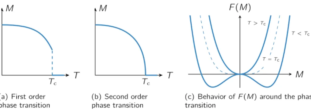
Lowering the temperature, one first enters an intermediate regime (IM), i.e., the fluctuation disordered regime [22–24]. It is a crossover region between the paramagnetic and magnetically ordered phases. On a mean-field level one obtains a second-order phase transitions, but fluctuations drive it to first order.
After said first order transition at a critical temperatureTcone enters an ordered phase. At zero magnetic field this is thehelical phase where magnetization forms
1. Introduction
a twisted structure as shown infigure 1.3(a). Note, that the local magnetization is perpendicular to the helix pitch and hence does not carry any mean magnetization.
At zero field, the pitch direction is determined by cubic anisotropies [25,26] and the formation of domains with different pitch directions is possible. Upon applying and increasing an external magnetic fieldHext, the system transitions from a helical into a conical arrangement. First, all pitch vectors start to align with the direction ofHint, which generally comprises ofHext, demagnetization and anisotropy effects, but mostly corresponds to the directionHext, especially for higher fields. This process is completed at a critical field strength Hc1. For more details see section 3.4. After that, the magnetization tilts towards Hint forming a conical shape, as shown infigure 1.3(b), and generating a finite mean magnetization also pointing towardsHint. This is theconical phase.
Increasing the magnetic field makes the cone more and more acute until it vanishes and afield polarized orferromagnetic state(FM) is obtained,figure 1.3(c).
This happens at a critical fieldHc2 and the phase transition is of second order, i.e., the magnetization changes continuously.
Just belowTc and at a finite magnetic field betweenHc1 and Hc2, roughly at 0.5Hc2, there exists a small phase pocked indicated as theA-phaseinfigure 1.2. It contains a trigonal lattice of magnetic whirls, so-called skyrmions. An impression of thisskyrmion latticeorskyrmion crystal phaseis shown infigure 1.3(d). More details are given inchapter 2.
1.3. Materials & Properties
By today, many materials exhibiting the previously described phases have been found and investigated. The initial spark that ignited growing interest and re- search on, at first, chiral magnets, was the discovery of a skyrmion lattice phase in MnSi [7]. From then on, a lot of effort has been put into creating and studying materials that might be able to host skyrmions natively, cf.chapter 2.
The focus of this thesis lies on models that apply to study bulk chiral mag- nets with corresponding experiments being conducted by collaborators on MnSi, Fe1–xCoxSi and Cu2OSeO3. The first two crystallize in a cubic B20 alloy struc- ture, which is a name for the FeSi-structure type, but all three have the space groupP213of point group 23, cf. No. 198 in [27]. This space group lacks a center of inversion, which leads to the existence of both left and right handed versions of the crystals. The selection process can depend on the substrate or seed on top of which the crystals are grown. It hands down their own chirality to the sample.
In the following, we describe those three materials in more detail. Characteristic parameters are summarized intable 1.1 on page14.
8
1.3. Materials & Properties
Mn Si
(a) Unit cell of MnSi. Manganese atoms (orange) have an atomic radius of 127 pm while the silicon atoms (blue) are only a little bit smaller with a radius of 117.6 pm [16].
(b) Magnetic susceptibility measurements in MnSi [21].
Figure 1.4: B20 crystal structure and magnetization measurements of MnSi.
Manganese Silicide: MnSi
This material is a metallic, itinerant-electron magnet [3]. The cubic structure has an edge length ofaMnSi= (4.5480±0.0002)Å[16] forming a cube containing eight atoms per unit cell, i.e., four formula units, and their positions are defined by the following coordinates:
3(u,u,u); (1 2 +u,1
2≠u, ¯u); (1
2 ≠u, ¯u,1
2 +u); (¯u,1 2+u,1
2 ≠u)4
(1.5) withuMn= 0.138anduSi= 0.845[5], cf.figure 1.4(a). The magnetization in the ferromagnetic state comprises0.4µB per Mn atom [28].
Furthermore, MnSi can be grown in an ultra-pure form with a mean free path of up to 5000 Å which suggests a good description by Fermi-liquid theory, a theo- retical model dating back to Landau that is able to describe the normal state of most metals at sufficiently low temperatures. MnSi, however, shows an uncharac- teristic behavior for Fermi-liquids above a critical pressurepc. At lower pressures, when the system is weakly spin polarized, the resistivityfldepends quadratically on temperature as is expected by Fermi-liquid-theory. When magnetic order is suppressed atp > pc, this behavior changes abruptly toflÃT3/2 [6,29–33]. Note that this phenomenon is not only confined to an area close to the quantum critical point but over a wider area of the phase diagram. Reasons for the appearance of this non-Fermi-liquid phase are still unknown and its understanding is sometimes referred to as the holy grail of MnSi.
The magnetic phase diagram of MnSi was already shown infigure 1.2. Below a critical temperature ofTc¥29 K, the system exhibits helical magnetic order at zero or small magnetic field [3, 34, 26]. The pitch vector Q is pinned to a
1. Introduction
a
CoSi Fe0.5Co0.5Si FeSi
Fe0.5Mn0.5Si MnSi0
50 100
T(K)
HMM PMM
PMI
PMM
HMM Fe1 –xMnxSi Fe1 –yCoySi
Figure 1.5: Effects of doping and temperature on Fe1 –xMnxSi (left) and Fe1 –xCoxSi (right).
Paramagnetic metallic (PMM), paramagnetic insulating (PMI) and helimagnetic metallic at zero field (HMM) phases are possible [38].
È1 1 1Ídirection in the helical phase via cubic anisotropies and the corresponding wavelength is approximately 180 Å long and almost temperature independent. In terms of chirality it can be said that a left handed chirality of the crystal structure corresponds to a left handed magnetic chirality [35,36].
Another important property concerns the magnetic susceptibility in the conical phase ‰con. The striking feature is a constant behavior at low temperatures.
Measurements have, for example, been performed by Bauer et al.[21] and are shown infigure 1.4(b). The slope of magnetization vs. applied field is truly linear for temperatures around 2 K, but softens out a little bit for higher temperatures.
This is still fine for small fields, but needs to be kept in mind for situations with comparably high temperatures and fields. As the magnetic field inside of a macroscopic sample depends on the strength of the shape dependent demagneti- zation field,‰con is also shape dependent. Said field can be characterized via a demagnetization factorNz corresponding to a principal axis in field direction, cf.
section 3.3. A shape independent constant, however, can be extracted via [37]
‰intcon= 1
‰≠1con≠Nz
. (1.6)
The material constant‰intconof MnSi has a value of 0.34. The property of a constant conical susceptibility is not reserved for MnSi alone, but occurs in the other chiral magnets as well. Values for other materials are listed intable 1.1.
Iron Cobalt Silicide: Fe
1– xCo
xSi
The magnetic and conducting properties of Fe1–xCoxSi depend on doping and temperature as can be seen in figure 1.5. When interested in helimagnets, most experiments are therefore conducted with a doping betweenx= 0.2andx= 0.5.
Like MnSi, both FeSi and CoSi also crystallize in a B20 structure which allows the full doping range.
10
1.3. Materials & Properties
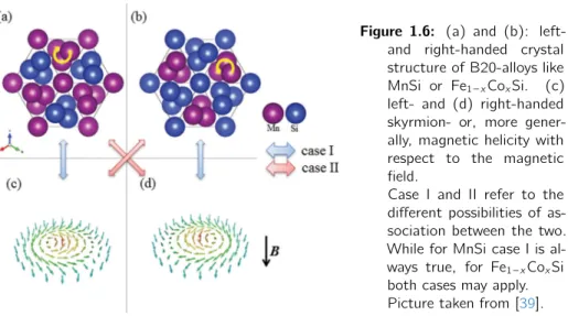
Figure 1.6: (a) and (b): left- and right-handed crystal structure of B20-alloys like MnSi or Fe1 –xCoxSi. (c) left- and (d) right-handed skyrmion- or, more gener- ally, magnetic helicity with respect to the magnetic field.
Case I and II refer to the different possibilities of as- sociation between the two.
While for MnSi case I is al- ways true, for Fe1 –xCoxSi both cases may apply.
Picture taken from [39].
The helix pitch is weakly oriented alongÈ1 0 0Íand in some measurements even a random distribution has been found [40].
Figure 1.6shows a B20 structure like iron cobalt silicide in both chiralities, illus- trated by yellow arrows.
Contrary to MnSi, the handedness of the magnetic spin structure does not always correspond to the handedness of the atomic crystal structure, i.e., a left handed crystal structure does not mean that magnetic helices or skyrmions have a left handed chirality as well (case I infigure 1.6), but can be exactly the opposite (case II). In Fe1–xCoxSi the association between crystal and magnetic chirality is doping dependent. That means choosing a fixed crystal chirality and changing the doping strength will flip the sign of the Dzyaloshinskii-Moriya interaction at a doping strength aroundx= 0.65[41].
The change of the Dzyaloshinskii-Moriya interactionD also influences the pitch length leading to a variation of the helix wavelength⁄helÃ1/Dbetween 200 and 2300 Å [42–44]. Dependent on doping,⁄helfirst decreases but soon increases with increasingx[40].
Copper(II)-oxo-selenite: Cu
2OSeO
3Below a critical temperature of 58.8 K CuSeO4 shows spontaneous magnetization [45]. Copper(II)-oxo-selenite in general can appear in a multitude of crystal struc- tures going from monoclinic and triclinic forms of Cu4O(SeO3)3 to Cu2O(SeO3), which can be monoclinic and even cubic. The latter is the type we focus on.
The material in question is a dark olive green multiferroic and magnetoelectric insulator. Comparing to MnSi, it crystallizes similar to the B20 structure but with a different coordination number. It contains eight formula units per unit
1. Introduction
Se O
Cu a
b c
(a) Cu2OSeO3crystal structure [47]
H || [111]
H || [110]
H || [001]
H [111]
H [110]
H [001]
p
ρ pz, ρ
+1
-1
[¯110]
[¯1¯10] [001]
[¯110]
[¯1¯12]
[¯110]
P = 0 P P
(b) Electric polarization in Cu2OSeO3[48]
Figure 1.7: (a) The empirical formula of Cu2OSeO3contains two Cu2+ ions. They are characterized by a different oxygen coordination.
(b) Top: depending on the direction of an applied magnetic fieldH with respect to the atomic lattice, a finite mean electric polarizationPis able to form with a direction also dependent on the direction of H.
(b) Bottom: besides a possibly finite mean polarization, the skyrmion phase experiences also a modulating local one that induces a local charge distributionflplotted in the bottom row of (b).
cell of edge length aCu2OSeO3= (8.9250±0.0001)Å[17]. A picture of the crystal structure is shown in figure 1.7(a). The helical magnetic modulation has a length of(616±45)Å and is pinned to aÈ1 0 0Ídirection at zero field [46].
In a magnetoelectric material, an external magnetic field influences electric polarization [49]. Although Cu2OSeO3 does not show spontaneous ferroelectric polarization, it can be induced by an external magnetic field [50]. For the setup used here, this polarization can locally be written as [51]
P =– Q aMyMz
MzMx
MxMy
R
b. (1.7)
The direction of the average polarization depends on the direction of applied magnetic field and may also vary on strength. When the system is in the skyrmion
12
1.3. Materials & Properties phase, then also the local polarization varies significantly with respect to the direction of the magnetic field. Both effects are shown in the top and bottom parts offigure 1.7(b), respectively. Electric forces are generally much stronger than magnetic forces, but the induced polarization has, nevertheless, only a small effect as can be seen, for example, when comparing magnetic and electric dipolar energies. Seki et al. measured a saturation magnetization between0.5µB/Cu2+
at 5 K and 0.2µB/Cu2+ at 57 K ¥ Tc for H Î [1 1 1] [47]. This corresponds to approximately 16µC/m2 and 1µC/m2 at H = Hc2, respectively. Having eight formula units per unit cell providing 16 copper ions responsible for the magnetic moments per unit cell, leads to
P[1 1 1]T=5 K= 16µC m2 M[1 1 1]T=5 K= 0.5 µB
Cu2+ ·16 Cu2+
710.8Å ¥104 000A m giving corresponding dipolar energies of
Edipole,electric = 1 8fi‘0
1P[1 1 1]T=5 K22
¥1 J m Edipole,magnetic = µ0
8fi
1M[1 1 1]T=5 K22
¥540 J m.
There are hence at least two to three orders of magnitude between those energies.
But because Cu2OSeO3is insulating, electric fields can still influence the magnetic structure without needing to worry about affecting itinerant charge carriers.
Summary and Other Noteworthy Materials
Table 1.1summarizes typical values of the materials above. One should mention, that temperature generally plays a role in all obtained data. It is ultimately a matter of focus which allows us to approximate some values as constant opposed to others. For example the lattice constants and hence theVf.u.(Å3)depend on temperature. We chose to mention low temperature values in the text, while values intable 1.1correspond to ambient temperatures. Their discrepancies are fairly small at about one percent. The pitch length varies more significantly with around 10 % between 0 K andTc [52]. The biggest influence of temperature can, however, be observed inHc2 which is around a factor of two. Therefore, the other temperature dependencies can be regarded as constant compared toHc2(T).
Apart from those three materials, there are, for one, more B20-type alloys like FeGe [57] or MnGe [58] that host skyrmions. To a great deal driven by the need for skyrmions at room temperature to be able to use them in applications and novel computer technologies (cf. section 2.3), other approaches were explored.
For example Heusler compounds like Mn2RhSn of space group I¯4m2(No. 119), as an example of other non-centrosymmetric magnets, are studied [59], but also
1. Introduction
MnSi Fe0.8Co0.2Si Cu2OSeO3 FeGe metallic semi-conducting insulating metallic
Tc(K) 29 28 58 278.2
Hc2int(T = 0) (µT0) 0.60 0.15 0.08 0.93atT=271K
2⇡/Q(Å) 180 340 600 700
pitch alignment h1 1 1i weaklyh1 0 0i h1 0 0i h1 0 0ihighT
h1 1 1ilowT
intcon 0.34 0.64 1.76 3.43
Vf.u.(Å3) 24.02 22.52 89.02 103.80
Z 4 4 8 4
g 2.0 2.1 2.1 1.9
Table 1.1: Summary of material properties. The number Z equals the number of formula units per unit cell and note thatpitch alignmentrefers to the direction ofQat zero field in the helical phase. Most values are taken from samples used in [37], the remaining sources are mentioned in the text and [53–56]. Note that the listed data for FeGe are for its low-temperature B20 structure.
centrosymmetric magnets, where Dzyaloshinskii-Moriya interaction does not play a role but the interplay between magnetic dipole–dipole interaction and uniaxial anisotropy causes the formation of a skyrmion spin texture. Also, broken inversion symmetry at interfaces can lead to the formation of skyrmions as can be seen in [60] where the authors create a square, atomic-scale skyrmion lattice in a one-atomic iron film on top of an iridium (1 1 1) surface. For a collection of materials see [61, chapter 2].
Although near-room temperature formation of a skyrmion lattice was already achieved in thin-films of FeGe [57], skyrmions at and beyond room temperature were first found in a different family of chiral magnets: —-Mn-type Co–Zn–Mn alloys. One example is Co10Zn10, which belongs to the cubic chiral space group P4132 orP4332 depending on its handedness containing 20 atoms in the unit cell and the critical temperature lies atTc¥462 K[62]. Doping with manganese systematically decreases Tc until Co6Mn6Zn8 does not show ferromagnetic be- havior any longer. The authors effectively detect skyrmions at 283 K and 345 K respectively for Co8Zn8Mn4and Co8Zn10Mn2.
14
2
Skyrmions
2.1. Historical Origin
Skyrmions date back to studies by T. H. R. Skyrme in the late 1950’s and early 1960’s [8, 63–67]. He developed a unified field theory of K- andfi-mesons and baryons. It turned out to be a non-linear theory of self-interacting (boson) meson fields, which admit states that have phenomenological properties of fermion particles, interacting with mesons. This was achieved by separating the field into meson-like and particle-like parts.
In the following we sketch his original work in a rough fashion and mainly follow the beginning of [67]. Let the initial field at any point be characterized by a unitary symbolU:
U U†=U†U = 1. (2.1)
While he also discussed simpler, one-dimensional models whereU corresponds to a complex number ei–, in the physically relevant caseU is a quaternion1, which can also be written in terms of four real fields„–:
U =„4+i ÿ3 –=1
·–„– (2.2)
where the coefficients·–are a set of three Pauli matrices. In his model, the three independent pion field amplitudes are replaced by such four fields, that interact symmetrically with the nuclear field. The vector composed of those fields is then constrained to have constant length:
ÿ4 –=1
„2–= 1. (2.3)
The domain of U is hence the surface of a unit-sphere in a four-dimensional Euclidean space. A constant of motion calledN, that can be interpreted as a
1Quaternions can be seen as an extension of the complex numbers. They have been discovered by Sir William Rowan Hamilton (1805–65) and are the first non-commutative algebra to be studied [68].
2. Skyrmions
particle number, has the global meaning of the number of times that the field distributionU(x)maps the 3-dimensional configuration space onto this domain.
U has to obey the boundary condition
U(Œ) = 1 (2.4)
to ensure an integer particle number. In a state where there is one particle,U has to wrap around the sphere at least once and therefore take the value of≠1 at least once. This leads to a native definition of the position of the particle, namely atx=x0 whenU(x0) =≠1. He then separatesU into amesonic partUˆ that never takes the value ≠1, and aparticle part, that is only significant in the vicinity ofx0. He gives
Uˆ = 1 +Á+U
1 +Á+U†, (2.5)
which is unequal to≠1forÁ>0. AsÁæ0 ˆU approaches U almost everywhere.
BecauseUˆ is particle free, i.e.,N = 0, a separation can be made as
U = ˆU S. (2.6)
Except near the positionsx0 of particles, the new fieldS= 1. Near particlesS can be written as
S=≠Á+i·–B–i(x≠x0)i
Á≠i·–B–i(x≠x0)i
. (2.7)
·– are the Pauli matrices andBi–are proportional to the field gradients of U at x=x0:
ˆU
ˆxi =i·–Bi–U (2.8)
B–i = (1/2i) Tr(U†·–ˆU
ˆxi). (2.9)
It then needed to be shown that singularities like S, describing the branch points of Ô
U, behave like Dirac particles coupled to the residual meson fieldU. Those are some longer calculations that we will not address here. Still noteworthy is a derived expression for the particle number (in the limit ofÁæ0)
N=≠sgndetB–i(x0). (2.10) At this point he believed that the particle operators have many fermionic prop- erties but did not show it explicitly. He did, however, demonstrate this for the one-dimensional model in [65] where neutrino-like properties were evident.
In retrospect Skyrme’s particle solutions, the now so-called skyrmion solutions, were the first example of a topological soliton model of a particle [69]. Seen in a broader context, they emerged from the Yukawa model which describes how heavy spin-12 nucleons interact through pion exchange. He reconsidered the pion
16
2.2. Topological Aspects of Skyrmions exchange which leads to a Lagrangian with a topological structure, that allowed a topologically stable soliton solution. He saw that these solutions had rotational degrees of freedom and the key was that when quantized, the state was allowed to carry spin-12. Hence, a bosonic field theory could lead to fermionic states.
While skyrmions occurred here as field configurations on a 3-sphere as defined by (2.12), the concept and their topological properties can be generalized to other dimensions, in particular to the 2-sphereS2. This brings us back to the texture shown infigure 1.3(d), the skyrmions present in chiral magnets. Because they are formulated in one dimension less than the original skyrmions, they are sometimes called baby-skyrmions. In contrast to objects in other magnetic phases present in chiral magnets they are topologically non-trivial. This aspect is elucidated in the following.
2.2. Topological Aspects of Skyrmions
Skyrmions or magnetic textures in general are described by a vector field, i.e., a mapping between two manifolds, in this example position and spin-direction.
This paragraph follows [69] to introduce topological characteristics and their application on the skyrmion structure.
Let
0:XæY (2.11)
x‘æy
be a map between two manifolds X andY. In particular, let there be points x0 œ X and y0 œ Y. In the following, we consider based maps, i.e., maps
0(x0) =y0. To formulate topological aspects in a proper way, the concept of homotopy is important. 1 homotopic to 0means, that 0 can be continuously deformed into 1. Homotopicis symmetric, transitive and reflexive, which are the properties of an equivalence relation. Proof can be found in [70]. Therefore, maps can be classified in homotopy classes. The constant class, for example, contains all maps that are homotopic to the constant map (x) =y0for allxœX. Of special interest to us are maps from a sphere to a target manifold.
Sn =)
xœRn+1:ÎxÎ= 1* (2.12) is the definition of an n-sphere, a sphere embedded in n+ 1 dimensions [71].
Based maps : SnæY from such a sphere are of a class infin(Y), which has a group structure for nØ1. In particularfi1(Y)is known as the fundamental group.
2. Skyrmions
Example: fi1(Y)
fi1(Y) is the class containing all maps of circles or loops that get mapped to a target Y. IfY is a connected manifold andfi1(Y) ={e}, where {e}is the trivial group containing only the identity element, thenY is simply connected.
This means, that all loops can be smoothly contracted to a single point. This, in turn, implies thatY does not have any holes.
If the target is a circle or loop itself, i.e., Y =S1, then there exists a map f:S1æS1withf(1) = 1. A mapf˜:RæS1is clearly induced byf(t) =˜ f(eit).
It can be shown that due tofi1(R) = 0every mapg:RæS1 withg(0) = 1can be uniquely lifted to a mapˆg:RæRwithg(0) = 0[71]. In particular, there exists a unique mapfˆwithf(0) = 0ˆ such that the diagram
R
p
✏✏R
fˆ
77
t‘æeit//S1
f //S1, commutes.
Clearly, there existskœZthatf(2fi) = 2fik. The numberˆ kcan be seen as a winding number that counts the number of times the image off winds around S1. It follows from the uniqueness of the lifting property that the winding number is well-defined.
The statement of the second part of the example can be generalized and reads
fin(Sn) =Z ’nØ1. (2.13)
For Skyrme’s original skyrmionsn= 3. The case of baby skyrmions, which we will simply call skyrmions in the remainder of the text, of course also falls into the same set of classes, only with n = 2. In that context, they can easily be drawn as arrows on a sphere like in the upper part of figure 2.1. The magnetic texture in chiral magnets is, however, set on a planar surface and not the surface of a sphere. That transition is achieved via a stereographic projection ofS2 onto R2. Letpbe the north pole of the sphere, then there exists a homeomorphism R2æS2\ {p}. A complete correspondence is obtained by adding a single point at infinity toR2and identifying it with the image ofp. A based map : S2‘æS2, or to any other target manifold for that matter, is hence a continuous extension of a map :R2æS2 provided thatlimxæŒ (x) =p. Of course, the occurring skyrmions have a finite extent, but a contraction ofR2is easily done, for example by applying the mapfl‘ætan≠1fl, or other less distorting functions, whereflis the distance to the origin ofR2. The result after such transformations is shown in the lower part offigure 2.1. On the left hand side so-called Néel-skyrmions are shown. They are characterized by having always outward-pointing spins on the sphere. Combing those spins around the axis connecting north and south pole of the sphere yields a sense of chirality that is, of course, also present in the
18
2.2. Topological Aspects of Skyrmions
Figure 2.1: Stereographical projections of (baby) skyrmions. The south pole of the sphere is mapped to the origin ofR2 while the north pole is mapped to infinity. Via the map
⇢7!tan 1(⇢)one can mapR2 onto a finite sized disk, where⇢is the distance to the origin. Left: Néel-skyrmion. Note the similarity to Néel-type domain walls, in which spins rotate in a plane perpendicular to the domain boundary. Right: Chiral- or Bloch-type skyrmion. Note the similarity to Bloch-type domain walls, in which spins rotate in a plane parallel to the domain boundary. It evolves from a Néel-skyrmion by firstcombingthe spherical hedgehog arrangement around the axis defined by the north and south poles of the sphere before projecting it onto a plane. This type is the one observed in chiral magnets.
projected version. This texture is then called chiral skyrmion and it is the type of texture that occurs in chiral magnets and therefore the kind of skyrmion that we refer to in the remainder of the thesis unless explicitly stated otherwise.
At this point, it is appropriate to give another quantity that characterizes the skyrmion. This is itswinding number . In the general mathematical scheme it is rooted in the concept of thetopological degree, which is defined for an everywhere continuously differentiable map : X æ Y between two oriented and closed manifolds of the same dimension. Then the topological degree is defined as the integral over the pullback ú of a normalized volume form on the targetY:
deg =⁄
X
ú( ). (2.14)
The topological degree is an integer number and therefore a homotopy invariant.
It also does not depend on [69].
2. Skyrmions
To make the transition from this abstract definition to the skyrmion configuration, let us specify the integrand of (2.14). Given =—(y)dy1·dy2 withyœY and let the map be represented byy(x), then the integrand is written in terms of local coordinates as
ú( ) =—(y(x))ˆy1
ˆxjdxj· ˆy2 ˆxkdxk
=—(y(x))J(x)dx1·dx2 (2.15) withJ(x) = det1ˆyi
ˆxj
2andi,j,kœ{1, 2}.
In the physical context the map describes the local magnetizationM(x)©y(x) and, when normalized,( ˆM)can be described by anglesËandÏof the standard spherical coordinates. Using those coordinates the normalized volume form specifies to = 4fi1 sin(Ë)dË·dÏ. We now need to pull this integration over a sphere back to an integration over R2 in Cartesian coordinates by inverting the spherical coordinate representation. To avoid an abundance of indices we set (x,y) = (x1,x2)œX.
Ë= arcsinÒ
Mˆx2+ ˆMy2 (2.16)
Ï= arctanMˆx
Mˆy
(2.17) Also, the explicit dependence on(x,y)has been dropped for clarity, i.e.,Mx= Mx(x,y) is the first component of the magnetization at position (x,y). Using those coordinates in (2.15) and evaluating the derivatives in the second step yields
degM = 1 4fi
⁄
R2sinËÒ
Mx2+My2 3ˆË
ˆx ˆÏ ˆy ≠ˆÏ
ˆx ˆË ˆy
4 dx dy
= 1 4fi
⁄
R2
Ò 1
1≠Mˆx2≠Mˆy2 AˆMˆx
ˆx ˆMˆy
ˆy ≠ˆMˆy
ˆx ˆMˆx
ˆy B
dx dy
= 1 4fi
⁄
R2
Ò 1
1≠Mˆx2≠Mˆy2 AˆMˆ
ˆx ◊ˆMˆ ˆy
B
z
dx dy. (2.18)
The normalization ofM is encoded in Mz =Ò
1≠Mx2≠My2. Furthermore, it can be shown that the last line can be written as a triple product, which results in the common form used to calculate the skyrmionwinding number W:
W = 1 4fi
⁄
R2
Mˆ ·1
ˆxMˆ ◊ˆyMˆ2
dx dy. (2.19) This number counts how often the magnetization wraps around a sphere. Applying (2.19) to a texture as shown in the bottom half offigure 2.1, one obtainsW =≠1.
Strictly speaking this object is called ananti-skyrmion. The minus sign appears because magnetization at the center is pointingdown.
20
2.3. Experimental Realization and Application
0.03 0.08 0.21 0.55 1.47 3.87 10.2 27.1 71.5 189 500
Counts / Std. mon.
B 0.08
0 qy(Å-1)
0.08 0
-0.08
qx(Å-1)
<110>
<111>
<100>
<111>
-0.08
Figure 2.2: Structure factors obtained via neutron scattering. Left: Helical/conical phase of the helimagnet Cu2OSeO3 [46]. Two peaks are clearly visible aligned with the magnetic field along which they represent the helical modulation. Right: Skyrmion phase in MnSi [7]. Six major peaks a visible indicating a superposition of three helices.
Additionally, smaller higher order peaks are recognizable. A more thorough study on them can be found in [74].
2.3. Experimental Realization and Application
Around the early 90’s, Bogdanovet al.showed, that such skyrmions may occur as a thermodynamically stable system of magnetic vortices in magnetically ordered crystals with an easy axis [9, 72, 73]. The vortices themselves form a lattice similar to that of type-II superconductors and can be stabilized by a so-called Dzyaloshinskii-Moriya interaction. Besides tetragonal materials like Tb3Al2, the authors also suggested cubic magnets like FexCo1–xSi and, in particular, MnSi as possible candidates to exhibit skyrmions.
In 2009, MnSi was subject to studies by a research group in Munich where Mühlbaueret al.performed small angle neutron scattering experiments (cf.sec- tion 5.2) on it while applying a magnetic field and thus inducing an easy axis of magnetization [7]. Contrary to previous experiments, they did not apply the incident neutron beam perpendicular to the magnetic field, but in parallel. Unlike two peaks in the structure factor that one expects at intermediate fields in the perpendicular setup indicating the conical phase, the result were six major peaks forming a hexagon around the center, cf.figure 2.2. Having a spirally modulated structure in mind when observing two opposing peaks it seemed natural to su- perpose three of them when seeing six peaks. Doing exactly that and properly fixing the relative phases amounts to the magnetic lattice structure shown in figure 1.3(d). This actually three dimensional texture is translation invariant in the direction parallel to the magnetic field, i.e., perpendicular to the shown plane, thus forming a tube-like structure similar to the Abrikosov vortex lattice of type-II superconductors. Atomic scale skyrmion have also been realized by using a surface Dzyaloshinskii-Moriya interaction [60]. There, the chirality is not an intrinsic property of a material but arises because of material differences between the substrate and the studied layer on top of it.
2. Skyrmions
Skyrmions have the prospect of becoming a key ingredient in future computer technology. Their topological structure leads to an emergent electrodynamics which can be used to couple them very efficiently to currents. Due to their incommensurability and large extent compared to the atomic lattice, skyrmion lattices can be moved by currents a million times smaller than needed to move ordinary magnetic domain walls [11, 75]. Novel ideas about applying single skyrmions range from racetrack memories [10,76,77] to entire logic elements.
22
3
Theoretical Description
The magnetic structure in bulk chiral magnets can be described by several methods.
In this thesis we primarily choose a description via a Ginzburg-Landau theory which we introduce in this chapter. In part III we also employ a description via a non-linear ‡ model, which restricts the magnetization to be normalized.
Before turning to the description of the theoretical model we introduce necessary quantities.
3.1. Conventions
In the following chapters we compare our models to data obtained by different experimental methods: ferromagnetic resonance and neutron scattering experi- ments. The first applies an oscillating external magnetic field, which enters the relevant equations, while the latter method focuses on much shorter length scales which makes it convenient to use the internal magnetic field in the describing equations. At this point we establish a connection between these quantities and define notation.
External quantities will be indicated by the index “ext” and internal quantities by an index “int”. Magnetic fields and inductions are therefore denoted by Hext andHint respectivelyBext andBint. While vectors are written in bold letters, their norms will mostly be denoted by normal font and omitted absolute value bars.
Magnetic moments are indicated byµand magnetization, which has units of magnetic moment over volume, by a capitalM. When encountering spatially ho- mogeneous quantities, they will carry an index “0”, i.e.,M0 orH0. Furthermore, (static) mean-field solutions carry an index “mf” likeMmf.
In the vacuum, the two magnetic fields B andH are just scaled versions of each other related by the permeability of free space µ0= 4fi◊10≠7N/A2:
B=µ0H. (3.1)
![Figure 1.2: Typical magnetic phase diagram of the exemplary chi-ral magnet MnSi. Picture taken from [21].](https://thumb-eu.123doks.com/thumbv2/1library_info/3705261.1506154/20.748.113.629.123.579/figure-typical-magnetic-phase-diagram-exemplary-magnet-picture.webp)


![Figure 4.3: Angle definiton for cubic anisotropies: Ë is the angle between [0 0 1] = e ˆ a z and the magnetization M s , while angle Ï is the angle between [1 0 0] and the projection of M s onto the plane spanned by [1 0 0] and [0 1 0]](https://thumb-eu.123doks.com/thumbv2/1library_info/3705261.1506154/62.748.212.532.123.420/figure-angle-definiton-cubic-anisotropies-magnetization-projection-spanned.webp)